EP1349302A2 - Réseaux de transmission optiques - Google Patents
Réseaux de transmission optiques Download PDFInfo
- Publication number
- EP1349302A2 EP1349302A2 EP03075840A EP03075840A EP1349302A2 EP 1349302 A2 EP1349302 A2 EP 1349302A2 EP 03075840 A EP03075840 A EP 03075840A EP 03075840 A EP03075840 A EP 03075840A EP 1349302 A2 EP1349302 A2 EP 1349302A2
- Authority
- EP
- European Patent Office
- Prior art keywords
- dispersion
- optical
- signal
- transmitter
- fibre
- Prior art date
- Legal status (The legal status is an assumption and is not a legal conclusion. Google has not performed a legal analysis and makes no representation as to the accuracy of the status listed.)
- Withdrawn
Links
Images


Classifications
-
- H—ELECTRICITY
- H04—ELECTRIC COMMUNICATION TECHNIQUE
- H04B—TRANSMISSION
- H04B10/00—Transmission systems employing electromagnetic waves other than radio-waves, e.g. infrared, visible or ultraviolet light, or employing corpuscular radiation, e.g. quantum communication
- H04B10/25—Arrangements specific to fibre transmission
- H04B10/2507—Arrangements specific to fibre transmission for the reduction or elimination of distortion or dispersion
- H04B10/2513—Arrangements specific to fibre transmission for the reduction or elimination of distortion or dispersion due to chromatic dispersion
- H04B10/25137—Arrangements specific to fibre transmission for the reduction or elimination of distortion or dispersion due to chromatic dispersion using pulse shaping at the transmitter, e.g. pre-chirping or dispersion supported transmission [DST]
Definitions
- the invention relates to optical networks and in particular to transmitter systems for optical networks.
- modulated optical signals are transported between network points or nodes by optical fibres.
- the signals are generated at transmitter modules which typically comprise an optical or light source, such as a laser diode, and a modulator, such as a Mach Zehnder or electroabsorption modulator.
- Chromatic dispersion is a deleterious effect around which optical networks are designed.
- Each pulse in a digital, modulated optical signal has a spectrum of wavelengths and the refractive index of an optical fibre varies with wavelength.
- wavelengths at the leading edge of the pulse may propagate faster than wavelengths at the trailing edge, and the pulse will be caused to broaden or spread.
- the extent of broadening is related to the length of fibre traversed, and there comes a point or fibre length limit at which a pulse is too severely affected to be discernible and detectable at a receiver. At least, this is the case with standard transmission fibre, so-called non-dispersion shifted fibre (NDSF).
- NDSF non-dispersion shifted fibre
- Other types of fibre such as, for example, Truewave, also give rise to broadening but as the dispersion is less, the broadening is at a lower rate.
- Figure 1 is a graph of dispersion penalty against distance travelled by an optical signal sent along an NDSF.
- An NDSF can tolerate a certain amount of penalty, up to the acceptable penalty limit P max .
- the P max limit defines the window of acceptable dispersion for the link, that is, the length X max of fibre up to which the penalty P does not exceed the penalty limit P max .
- the window of acceptable dispersion may be manipulated.
- Chirp is a difference in frequency dictated by the relationship between the phase and the intensity of a modulated optical signal with time. Chirp may be either zero, positive or negative.
- Pulse compression within reason, does not compromise the operation of the link, and signals from a transmitter at the head of the link can be sent any distance along the link, so long as the distance is within the window of acceptable dispersion, without requiring dispersion compensation. In other words, a signal sent along the link will be discernible at a receiver placed between the transmitter and a distance X max away from the transmitter.
- wavelength division multiplexed In the wavelength division multiplexed (WDM) environment, transmission bands are divided into wavelength channels which are combined generally at a multiplexer and sent together as a multiplexed stream.
- optical networks In simple links, such as single channel point-to-point links, this is more straightforward because there is only a single channel and a known distance.
- state of the art optical networks tend to be more complex and are no longer necessarily single channel or point-to-point links.
- Latest networks may include optical switching where a whole fibre may be switched to a different route for protection/restoration or to adapt to changes in traffic flow.
- wavelength routing different wavelengths may propagate over different fibre routes using add/drop multiplexers. Dynamic wavelength routing is where flexible add/drop multiplexers are used so that the path that a signal follows can be altered.
- Dispersion compensating modules are commonly used to offset the effects of dispersion.
- a dispersion compensating module is selected which has a dispersion characteristic of equal magnitude and opposite sign to the link fibre.
- the module comprises a length of dispersion compensating fibre.
- the module may comprise a fibre grating, higher order mode fibre or a photonic crystal fibre.
- MZ modulators are, at present, in more common use than electroabsorption (EA) modulators.
- EA modulators electroabsorption
- a MZ modulator will be co-packaged with a distributed feedback laser (DFB).
- DFB distributed feedback laser
- MZ modulators are relatively easy to make negative chirp but the downside is that it is very difficult to integrate them with a semi-conductor laser.
- Preferred laser semi-conductor materials are incompatible with preferred MZ modulator semi-conductor materials.
- EA modulators may be relatively easily integrated with semi-conductor lasers and, whilst they can readily be made to produce positive chirp, their downside is that it is quite difficult reliably to make them produce negative chirp.
- US 5877881 describes the use of positive chirp to overcome the limitations imposed upon an optical link by self phase modulation (SPM). This occurs at high optical powers whereby the Kerr effect gives rise to an intensity dependent phase shift which appears as negative chirp in the signal. This negative chirp can result in pulse narrowing in the presence of a positive dispersion transmission fibre. However, the combination of negative chirp and SPM can result in excessive negative chirp causing pulses to narrow very quickly and then rebroaden quickly. Consequently, the dispersion compensating element at the transmitter or receiver has to be very closely matched to the transmission fibre in order that the pulses are discernible at the receiver. US 5877881shows that it is possible to achieve a specific transmission distance with fewer values of dispersion compensating element at the transmitter and receiver when positive chirp is used.
- SPM self phase modulation
- signal powers tend to be lower than on point-to-point single channel links in order to reduce interactions between adjacent channels.
- Such interactions like cross phase modulation (XPM) or four wave mixing (FWM) tend to dominate over the single channel SPM effect.
- the present invention seeks to provide an improved optical transmission system.
- an optical transmitter system comprising a transmitter module adapted to produce a modulated optical signal discernible over a positive dispersion range x and a negative dispersion range y, and a dispersion element adapted to apply dispersion to the modulated optical signal, wherein the dispersion element is adapted to apply negative dispersion of magnitude substantially that of y, such that, when combined with the modulation of the light, the system is adapted to transmit a signal over a transmission link having any value of dispersion up to and substantially including (x + y), or the dispersion element is adapted to apply positive dispersion of magnitude substantially that of x, such that, when combined with the modulation of the light, the system is adapted to transmit a signal over a transmission link having any value of dispersion up to and substantially including - (x + y).
- the preferred dispersion element is a fibre Bragg grating (FBG), particularly a linear chirped FBG. If the optical source is tunable, the preferred dispersion element is an FBG with a repeating response, which may be formed by periodically sampling the grating. In a WDM environment, each repeating response may be aligned to a channel wavelength.
- FBG fibre Bragg grating
- the dispersion element may be a dispersion compensating fibre, higher order mode fibre, photonic crystal fibre, photonic bandgap waveguide, etalon (including MEMs), ring-resonator, cascaded Mach-Zehnder, virtually imaged phased array or arrayed waveguide grating.
- dispersion element may be inherently polarisation dependent or it may be made polarisation dependent.
- an asymmetry may be introduced into the lattice structure which well defines a polarisation axis, for instance, by filling in some of the holes in the lattice structure or by introducing an asymmetry in the positioning of the holes.
- the advantage of making the element polarisation sensitive is that the polarisation is well known and so the module and the element may be readily arranged in relation to one another such that the polarisation axis of the modulated optical signal matches the polarisation axis of the element.
- a polarisation maintaining component such as a fibre tail, may be introduced between the modulator and the element, although this adds an additional optical interface which may culminate to increased loss and the cost of the system.
- dispersion element In a WDM environment, it is desirable to share components and reduce cost. If the dispersion element is polarisation dependent, it would ordinarily be necessary to either have a separate element for each wavelength or a polarisation maintaining multiplexer.
- An alternative arrangement would be a dispersion compensating element having a plurality of waveguides so that each wavelength could be coupled to a different waveguide a dispersion applied independently of any other. In other words, a plurality of wavelengths could have dispersion applied by the same, single dispersion element.
- the lattice structure of a phototonic crystal fibre could be arranged as to offer a plurality of dependent, parallel waveguides.
- the wavelengths could be connected at the output of the element and multiplexed together. Such multiplexing could be achieved either by a single lens arrangement or a fibre coupling to a conventional multiplexer.
- dispersion element may, alternatively, be disposed on an optical receiver system.
- an optical receiver system suitable for receiving an optical transmission signal discernible over a positive dispersion range x and a negative dispersion range y, comprising a dispersion element adapted to apply dispersion to the optical transmission signal, wherein the dispersion element is adapted to apply negative dispersion of magnitude substantially that of y, such that, the receiver is adapted to receive a signal over a transmission link having any value of dispersion up to and substantially including (x + y), or the dispersion element is adapted to apply positive dispersion of magnitude substantially that of x, such that, the receiver is adapted to transmit a signal over a transmission link having any value of dispersion up to and substantially including - (x + y).
- a further aspect of the invention provides a method of compensating dispersion in an optical network comprising the steps of, providing a transmitter module and a dispersion element, wherein the transmitter module produces a modulated optical signal discernible over a positive dispersion range x and a negative dispersion range y, and wherein the dispersion element applies a negative dispersion of magnitude substantially to that of y, such that, when combined with the modulation of the light, the transmitter system is adapted to transmit a signal over a transmission link having any value of dispersion up to and substantially including (x + y) or the dispersion element applies a positive dispersion of magnitude substantially to that of x, such that, when combined with the modulation of the light, the transmitter is adapted to transmit a signal over a transmission link having any value of dispersion up to and substantially including -(x + y).
- tangible signal means a signal whose state as a result of the net effects of negative and positive dispersion is such as to allow it to be reliably detected.
- the system according to the invention does not have to be configured, that is, the dispersion element does not require selection from a range of alternatives, in order to match the system for use in conjunction with a specific optical fibre transmission distance.
- One system, with one particular value of chirp and one particular value of dispersion may be used in conjunction with various optical fibre transmission distances and different links, which may be point-to-point or could be static wavelength routed or dynamically reconfigurable.
- a system according to the invention is considered from the point of view of a window of acceptable dispersion.
- the window of acceptable dispersion can be thought of as being shifted so that it coincides with the dispersion introduced by the NDSF, or other positive dispersion fibre.
- an optical transmitter system suitable for transmitting optical signals along a transmission fibre, comprising a light source adapted to emit light, a modulator operable to modulate the light to produce a modulated optical signal, and a dispersion element adapted to apply dispersion to the modulated optical signal thereby producing a transmission signal discernible at a point along the transmission fibre, wherein the modulator is adapted to apply positive chirp to the optical signal to produce a positively chirped modulated optical signal, and the dispersion element is adapted to apply negative dispersion to the positively chirped modulated optical signal, thereby producing a transmission signal discernible at a point, along a positive dispersion transmission fibre, in a range between a minimum and maximum distance relative to the transmitter system.
- a further aspect of the present invention provides a method of compensating dispersion in an optical network comprising the steps of, providing a transmitter having an optical source, a modulator and a dispersion element, emitting light from the optical source, applying modulation to the light to produce a modulated optical signal, applying dispersion to the modulated optical signal, wherein the applied modulation is of positive chirp and the applied dispersion is negative, thereby producing an optical signal discernible at a point, along a positive dispersion transmission fibre, in a range between a minimum and maximum distance relative to the transmitter system.
- dispersion element may, alternatively, be disposed on an optical receiver system.
- a further aspect of the present invention provides an optical receiver system, suitable for receiving an optical transmission signal transmitted along a fibre, comprising a dispersion element adapted to apply dispersion to the optical transmission signal to produce a discernible signal relative to that which was transmitted at a point along the fibre, in a range between a minimum and a maximum distance relative to the receiver, and optical detection means operable to detect the discernible signal, wherein the fibre is of positive dispersion and the dispersion element is adapted to apply negative dispersion to the optical transmission signal.
- ILMs tend to include an optical isolator, but this may be omitted for this application if the negative dispersion element is a fibre Bragg grating (FBG), operable in reflection. Coupling of the ILM and the FBG is via an optical circulator which itself provides optical isolation from light reflected back from the system towards the source, thereby removing the need for the ILM to have an optical isolator.
- FBG fibre Bragg grating
- a tunable optical source may be utilised. Furthermore, using a tunable source reduces the number of different parts required to set up a system and also reduces the number of different spare parts required.
- tunable optical source is not limited to agile networks and is generally applicable to any other type of system or network.
- An alternative to using a separate optical source and a modulator would be to have a directly modulated source, such as a directly modulated laser.
- the directly modulated laser would also be positively chirped.
- the maximum distance is determined by a combination of the chirp parameter of the positive chirp applied to the modulated optical signal and the negative dispersion to which the chirped modulated optical signal is subjected.
- the positive chirp parameter may be about +0.7 and the negative dispersion value may have a magnitude of 1700ps/nm.
- the minimum distance away may be at the transmitter, that is, may be equal to zero. Alternatively, the minimum distance may be greater than zero. If a minimum link length is to be used, it is possible to increase the value of negative dispersion so as to increase the system reach.
- a transmitter system may include a plurality of optical sources and a modulator for each source, and the outputs of the modulators may be combined and sent to the same dispersion element.
- the dispersion element may be shared.
- the transmitter system according to the invention is particularly suited to use in the WDM environment.
- the system according to the invention provides a "one size fits all" or “plug and play” solution.
- the system according to the invention with a fixed chirp and a fixed dispersion compensation, can be used in a whole range of different links, which may be point-to-point, or could be static wavelength routed or dynamically reconfigurable.
- a further aspect of the present invention provides an optical transmitter system, suitable for transmitting optical signals along a transmission fibre, comprising a light source adapted to emit light, a modulator operable to modulate the light to produce a modulated optical signal, and a dispersion element adapted to apply dispersion to the modulated optical signal thereby producing a transmission signal discernible at a point along the transmission fibre, the point wherein the modulator is adapted to apply phase optimised binary to the optical signal to produce a phase optimised binary modulated transmission signal.
- a still further aspect of the present invention provides a method of compensating dispersion in an optical network comprising the steps of, providing a transmitter having an optical source, a modulator and a dispersion element, emitting light from the optical source, applying modulation to the light to produce a modulated optical signal, applying dispersion to the modulated optical signal, wherein the modulator is adapted to apply phase optimised binary to the optical signal to produce a phase optimised binary modulated transmission signal.
- dispersion element may, alternatively, be disposed on an optical receiver system.
- a further aspect of the present invention provides an optical receiver system, suitable for receiving an optical transmission signal transmitted along a fibre, comprising a dispersion element adapted to apply dispersion to the optical transmission signal to produce a discernible signal relative to that which was transmitted at a point along the fibre, in a range between a minimum and a maximum distance relative to the receiver, and optical detection means operable to detect the discernible signal, wherein the optical transmission signal is a phase optimised binary modulated signal.
- phase optimised binary signal is sometimes (incorrectly) also referred to as a "Phase duobinary signal”.
- the dispersion window in relation to a phase optimised binary modulated signal characteristically extends both negatively and positively. If dispersion of a suitable magnitude is applied to the phase optimised binary modulated signal, by the dispersion element, the dispersion window is shifted to extend the maximum distance along a fibre at which a transmission signal is discernible.
- the suitable magnitude of dispersion, applied by the dispersion element is typically greater than 2000 ps/nm, and preferably in the range of -2700 to -4300 ps/nm for a positive dispersion fibre of approximately 200Km NDSF, and in the range of +2700 to +4300 ps/nm for a negative dispersion fibre of approximately 200Km in reach.
- an optical transmitter system suitable for transmitting optical signals along a transmission fibre, comprising a light source adapted to emit light, a modulator operable to modulate the light to produce a modulated optical signal, and a dispersion element adapted to apply dispersion to the modulated optical signal thereby producing a transmission signal discernible at a point along the transmission fibre in a range between a minimum and a maximum distance relative to the transmitter system, wherein the modulator is adapted to apply substantially zero chirp to the optical signal.
- a further aspect of the present invention provides a method of compensating dispersion in an optical network comprising the steps of, providing a transmitter having an optical source, a modulator and a dispersion element, emitting light from the optical source, modulating the light to produce a modulated optical signal, applying dispersion to the modulated optical signal, wherein the modulator is adapted to apply substantially zero chirp to the optical signal to produce a phase optimised binary modulated transmission signal.
- dispersion element may, alternatively, be disposed on an optical receiver system.
- a further aspect of the present invention provides an optical receiver system, suitable for receiving an optical transmission signal transmitted along a fibre, comprising a dispersion element adapted to apply dispersion to the received optical transmission signal to produce a discernible signal relative to that which was transmitted at a point along the fibre, in a range between a minimum and a maximum distance relative to the receiver, and optical detection means operable to detect the discernible signal, wherein the optical transmission signal is a substantially zero chirped modulated optical signal.
- the dispersion window of a substantially zero chirped optical signal characteristically extends both negatively and positively.
- Dispersion of a suitable sign and magnitude, applied by the dispersion element on the modulated signal shifts the dispersion window to extend the maximum distance along a fibre at which a transmission signal is discernible.
- dispersion in the range of approximately -900 to -1300 ps/nm is typically applied.
- dispersion in the range of approximately +900 to +1300 ps/nm is typically applied.
- a transmitter system according to the invention may be incorporated into an existing optical network such that the network consists of a mixture of existing transmitters, which may be of conventional negative chirp, and transmitter systems according to the invention.
- a further aspect of the invention provides an optical network comprising at least one of any of the abovementioned embodiments of optical transmitter systems, located at one or more points in the network, and a plurality of receiver systems each located at other points in the network, wherein each of the receiver systems are located a range of distances away from the, or each, transmitter system and the or each transmitter system is adapted to establish a point to point link with any of the receivers.
- a further aspect of the invention provides an optical network comprising at least one of any of the abovementioned embodiments of optical transmitter systems, linked, via a transmission path, to at least one receiver system, and at least one alternative transmission path between the, or each, optical transmitter and the, or each, receiver system, wherein the, or each, transmitter system is adapted to establish a link to the, or each, receiver system using one or more of the alternative transmission paths.
- a further aspect of the present invention provides an optical network comprising a plurality of any of the abovementioned embodiments of optical receiver systems, each located at one of a plurality of points in the network, and at least one transmitter system located at another point in the network, wherein the, or each, transmitter system is a range of distances away from each of the receiver systems, each receiver system adapted to establish a point-to-point link with the, or each, transmitter system.
- the present invention also further provides for an optical network comprising at least one of any one of the abovementioned embodiments of optical receiver systems, linked, via a transmission path, to at least one transmitter system, and a plurality of alternative transmission paths between the, or each, optical receiver system and the, or each, transmitter system, wherein the, or each, receiver system is adapted to establish a link to one or more transmitter systems using one or more of the alternative transmission paths.
- a further aspect of the present invention provides for an optical communication system, comprising a transmitter system linked, via a transmission link to a receiver system, the transmitter system comprising an optical source adapted to emit light, a modulator operable to modulate the light to produce a modulated optical signal discernible over a positive dispersion range x and a negative dispersion range y, the communication system also comprising a dispersion element adapted to apply dispersion to the modulated optical signal, wherein the dispersion element is disposed on at least one of the transmitter system and receiver system, and is adapted to apply negative dispersion of magnitude substantially that of y, such that, when combined with the modulation of the light, the transmitter is adapted to transmit a signal over a transmission link having any value of dispersion up to and substantially including (x + y), or the dispersion element is adapted to apply positive dispersion of magnitude substantially that of x, such that, when combined with the modulation of the light, the transmitter is adapted to transmit a signal over a transmission link having any
- the present invention further provides a signal as generated by or transmitted by a transmitter or any other aspect of the invention as aforementioned.
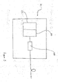
- a transmitter module 1 has an optical source 2, a modulator 4, coupling means 6 and a dispersion element 8. An output 10 from the modulator 4 is input to the coupling means 6. An input/output 12 from the coupling means 6 is connected to the dispersion element 8. An output 14 from the coupling means 6 is connected to a NDSF 16.
- the optical source 2 and the modulator 4 are a 10 Gbits/s DFB-electro absorption integrated laser modulator (ILM).
- the laser wavelength is positioned in relation to the edge of the ILM modulator absorption band so as to introduce pure positive chirp.
- a chirp factor ⁇ is also selected, in this specific case of + 0.7.
- the coupling means 6 is a three port circulator.
- the dispersion element is a linear chirped fibre Bragg grating (FBG) which has a bandwidth to fully cover the wavelength channels of interest but with sufficient guard bandwidth to cover any wavelength detuning effects that may occur due to ambient temperature variation.
- the output from the modulator is polarised and its axis of polarisation is aligned with the axis of polarisation of the FBG, which is polarisation dependent (although not all FBGs are polarisation dependent).
- a shorter fibre Bragg grating may be used with an athermal package design operable to compensate the wavelength shift associated with the thermal dependence of refractive index by an opposite wavelength shift through strain using materials of differing thermal expansion coefficients.
- the FBG has a dispersion of around -1700ps/m or, in combination with the positive chirp of +0.7, enough to compensate for approximately 100Km of standard positive dispersion NDSF.
- the magnitude and sign of the dispersion applied by the FBG is equivalent to the dispersion applied by traversing a "negative" amount of fibre.
- the net effect of combining a positively chirping modulator with a negative fibre element is to shift the dispersion tolerance window in comparison to a negatively chirped modulator.
- an alternative transmitter module 101 has an optical source 102, a modulator 104 and a dispersion element 108.
- the optical source 102 and the modulator 102 are an integrated laser modulator (ILM) as described for the transmitter module 1, of figure 2.
- ILM integrated laser modulator
- the dispersion element 108 is disposed thereon in line with the ILM.
- the coupling means 6 also acted as an isolator to isolate the light source from the system. Consequently, in the alternative transmitter module 101, the absence of such coupling means necessitates the need for means to isolate the optical source 102 from the system, such as, for example a bulk isolator within the ILM package.
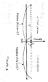
- dispersion penalty against positive dispersion fibre length is as shown by the solid line.
- a modulator could be utilised for traversing a positive dispersion fibre of up to XKm in length.
- the dispersion penalty against negative dispersion fibre length is as shown by the broken line.
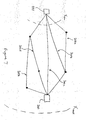
- a transmitter which produces a signal which is discernible at any of a range of points between a minimum and a maximum distance away from the transmitter may be used to make a point-to-point link with any of a number of receivers each of which is at a different distance away form the transmitter within the minimum to maximum range.
- a transmitter which produces a signal which is discernible at any of a range of points between a minimum and a maximum distance away from the transmitter may be used to make links with all of a number of receivers each of which is at a different distance away from the transmitter within a minimum and maximum range and connected to the transmitter by a different length path.
- a transmitter which produces a signal which is discernible at any of a range of points between a minimum and a maximum distance away from the transmitter may be used to make any one of a number of links with a receiver which is at a distance away from the transmitter within a minimum and maximum range and connected to the transmitter by a number of different length paths.
Landscapes
- Physics & Mathematics (AREA)
- Electromagnetism (AREA)
- Engineering & Computer Science (AREA)
- Computer Networks & Wireless Communication (AREA)
- Signal Processing (AREA)
- Optical Communication System (AREA)
Applications Claiming Priority (4)
| Application Number | Priority Date | Filing Date | Title |
|---|---|---|---|
| US109218 | 1998-06-30 | ||
| US10/109,218 US20030185573A1 (en) | 2002-03-28 | 2002-03-28 | Optical transmission systems |
| US10/185,112 US20030185500A1 (en) | 2002-03-28 | 2002-06-28 | Optical transmission systems |
| US185112 | 2002-06-28 |
Publications (2)
| Publication Number | Publication Date |
|---|---|
| EP1349302A2 true EP1349302A2 (fr) | 2003-10-01 |
| EP1349302A3 EP1349302A3 (fr) | 2004-12-29 |
Family
ID=27807274
Family Applications (1)
| Application Number | Title | Priority Date | Filing Date |
|---|---|---|---|
| EP03075840A Withdrawn EP1349302A3 (fr) | 2002-03-28 | 2003-03-24 | Réseaux de transmission optiques |
Country Status (3)
| Country | Link |
|---|---|
| US (1) | US20030185500A1 (fr) |
| EP (1) | EP1349302A3 (fr) |
| CA (1) | CA2423622A1 (fr) |
Cited By (1)
| Publication number | Priority date | Publication date | Assignee | Title |
|---|---|---|---|---|
| WO2020178559A1 (fr) | 2019-03-06 | 2020-09-10 | Cambridge Enterprise Limited | Émetteur optique |
Families Citing this family (5)
| Publication number | Priority date | Publication date | Assignee | Title |
|---|---|---|---|---|
| US20030185573A1 (en) * | 2002-03-28 | 2003-10-02 | Fells Julian A. | Optical transmission systems |
| US7502567B2 (en) * | 2004-06-15 | 2009-03-10 | Avago Technologies Fiber Ip (Singapore) Pte. Ltd. | Electroabsorption-modulated Fabry-Perot laser and methods of making the same |
| US20060222373A1 (en) * | 2005-04-04 | 2006-10-05 | Giovanni Barbarossa | Methods for upgrading and deploying an optical network |
| US7577369B1 (en) | 2005-04-04 | 2009-08-18 | Avanex Corporation | Systems for deploying an optical network |
| JP5224310B2 (ja) * | 2006-08-31 | 2013-07-03 | 古河電気工業株式会社 | 垂直共振器型面発光レーザ |
Family Cites Families (7)
| Publication number | Priority date | Publication date | Assignee | Title |
|---|---|---|---|---|
| US5259048A (en) * | 1991-09-30 | 1993-11-02 | Kabushiki Kaisha Toshiba | Optical equalizer |
| JP3522044B2 (ja) * | 1996-04-19 | 2004-04-26 | 富士通株式会社 | 光伝送システム |
| JPH10242909A (ja) * | 1997-02-27 | 1998-09-11 | Fujitsu Ltd | 光伝送システム |
| GB9712020D0 (en) * | 1997-06-09 | 1997-08-06 | Northern Telecom Ltd | Equalisation, pulse shaping and regeneration of optical signals |
| JP3440895B2 (ja) * | 1999-09-09 | 2003-08-25 | 日本電気株式会社 | 分散補償装置 |
| KR100337704B1 (ko) * | 2000-07-04 | 2002-05-22 | 윤종용 | 전계흡수형 변조기가 집적된 레이저 다이오드의 제조 방법 |
| US7099597B2 (en) * | 2000-08-25 | 2006-08-29 | Pts Corporation | Method of adaptive signal degradation compensation |
-
2002
- 2002-06-28 US US10/185,112 patent/US20030185500A1/en not_active Abandoned
-
2003
- 2003-03-24 EP EP03075840A patent/EP1349302A3/fr not_active Withdrawn
- 2003-03-28 CA CA002423622A patent/CA2423622A1/fr not_active Abandoned
Cited By (2)
| Publication number | Priority date | Publication date | Assignee | Title |
|---|---|---|---|---|
| WO2020178559A1 (fr) | 2019-03-06 | 2020-09-10 | Cambridge Enterprise Limited | Émetteur optique |
| US12081319B2 (en) | 2019-03-06 | 2024-09-03 | Cambridge Enterprise Limited | Optical transmitter |
Also Published As
| Publication number | Publication date |
|---|---|
| CA2423622A1 (fr) | 2003-09-28 |
| EP1349302A3 (fr) | 2004-12-29 |
| US20030185500A1 (en) | 2003-10-02 |
Similar Documents
| Publication | Publication Date | Title |
|---|---|---|
| US6233080B1 (en) | Crosstalk-free signal source for dense wavelength division multiplexed systems | |
| US6185023B1 (en) | Optical add-drop multiplexers compatible with very dense WDM optical communication systems | |
| US5726784A (en) | WDM optical communication system with remodulators and diverse optical transmitters | |
| US7269358B2 (en) | Optical transmitter for increased effective modal bandwidth transmission | |
| US8331786B2 (en) | Transmission method of WDM light and WDM optical transmission system | |
| US7061657B1 (en) | Multichannel optical communication system and method utilizing wavelength and coherence division multiplexing | |
| JPH0799478A (ja) | ファイバオプティック送信システムの分散補償装置と方法 | |
| KR950704878A (ko) | 동일한 광섬유상에 상이한 파장을 갖는 정보 신호를 송신하는 광 통신 시스템(an optical communications system for transmitting information signals having different wavelenghts over a same optical fiber) | |
| EP0826271B1 (fr) | Procede et appareil de transmission de signaux dans une fibre optique | |
| US6607311B1 (en) | Method and system transmitting optical signals generated by multi-line sources via WDM optical network | |
| US11243356B2 (en) | Chromatic dispersion compensation | |
| Sharma et al. | WDM ring network using a centralized multiwavelength light source and add-drop multiplexing filters | |
| CN100578973C (zh) | 波分复用光传输系统以及波分复用光传输方法 | |
| EP1349302A2 (fr) | Réseaux de transmission optiques | |
| US7019907B2 (en) | Integrated lithium niobate based optical transmitter | |
| US20030185573A1 (en) | Optical transmission systems | |
| EP1137204A1 (fr) | Dispositif a source lumineuse a longueur d'onde multiple fonctionnant avec un circuit a retard optique annulaire | |
| JP4957234B2 (ja) | 光信号伝送装置 | |
| US20190214782A1 (en) | Phase shifter for an optical phase-sensitive amplifier | |
| EP1233562B1 (fr) | Schéma de modulation et système de transmission pour signaux NRZ avec filtrage des côtés gauche et droit | |
| JP4386786B2 (ja) | 光通信システム | |
| KR100342429B1 (ko) | 광 필터링 방법에 의한 직접변조 방식의 메트로 파장분할다중방식 시스템 | |
| US7302194B2 (en) | Optical filter and transmission system incorporating an optical filter | |
| US10355784B2 (en) | Method and optical transmitter device for creating an optical binary digital transmit signal | |
| US20070166039A1 (en) | Integrated optical transmitter |
Legal Events
| Date | Code | Title | Description |
|---|---|---|---|
| PUAI | Public reference made under article 153(3) epc to a published international application that has entered the european phase |
Free format text: ORIGINAL CODE: 0009012 |
|
| AK | Designated contracting states |
Kind code of ref document: A2 Designated state(s): AT BE BG CH CY CZ DE DK EE ES FI FR GB GR HU IE IT LI LU MC NL PT RO SE SI SK TR |
|
| AX | Request for extension of the european patent |
Extension state: AL LT LV MK |
|
| PUAL | Search report despatched |
Free format text: ORIGINAL CODE: 0009013 |
|
| AK | Designated contracting states |
Kind code of ref document: A3 Designated state(s): AT BE BG CH CY CZ DE DK EE ES FI FR GB GR HU IE IT LI LU MC NL PT RO SE SI SK TR |
|
| AX | Request for extension of the european patent |
Extension state: AL LT LV MK |
|
| RIC1 | Information provided on ipc code assigned before grant |
Ipc: 7H 04B 10/155 B Ipc: 7H 04B 10/18 A |
|
| 17P | Request for examination filed |
Effective date: 20050629 |
|
| AKX | Designation fees paid |
Designated state(s): DE FR GB |
|
| GRAJ | Information related to disapproval of communication of intention to grant by the applicant or resumption of examination proceedings by the epo deleted |
Free format text: ORIGINAL CODE: EPIDOSDIGR1 |
|
| GRAP | Despatch of communication of intention to grant a patent |
Free format text: ORIGINAL CODE: EPIDOSNIGR1 |
|
| GRAP | Despatch of communication of intention to grant a patent |
Free format text: ORIGINAL CODE: EPIDOSNIGR1 |
|
| STAA | Information on the status of an ep patent application or granted ep patent |
Free format text: STATUS: THE APPLICATION IS DEEMED TO BE WITHDRAWN |
|
| 18D | Application deemed to be withdrawn |
Effective date: 20060808 |