EP1350423B1 - Ramasseur pour produits agricoles - Google Patents
Ramasseur pour produits agricoles Download PDFInfo
- Publication number
- EP1350423B1 EP1350423B1 EP03100187A EP03100187A EP1350423B1 EP 1350423 B1 EP1350423 B1 EP 1350423B1 EP 03100187 A EP03100187 A EP 03100187A EP 03100187 A EP03100187 A EP 03100187A EP 1350423 B1 EP1350423 B1 EP 1350423B1
- Authority
- EP
- European Patent Office
- Prior art keywords
- shaft
- housing
- pick
- mounting element
- rollers
- Prior art date
- Legal status (The legal status is an assumption and is not a legal conclusion. Google has not performed a legal analysis and makes no representation as to the accuracy of the status listed.)
- Expired - Lifetime
Links
- 239000000463 material Substances 0.000 abstract description 2
- 239000000969 carrier Substances 0.000 description 22
- 241001124569 Lycaenidae Species 0.000 description 2
- 230000008878 coupling Effects 0.000 description 2
- 238000010168 coupling process Methods 0.000 description 2
- 238000005859 coupling reaction Methods 0.000 description 2
- 239000004459 forage Substances 0.000 description 2
- HCHKCACWOHOZIP-UHFFFAOYSA-N Zinc Chemical compound [Zn] HCHKCACWOHOZIP-UHFFFAOYSA-N 0.000 description 1
- 238000005452 bending Methods 0.000 description 1
- 239000012858 resilient material Substances 0.000 description 1
- 230000000284 resting effect Effects 0.000 description 1
- 239000011701 zinc Substances 0.000 description 1
- 229910052725 zinc Inorganic materials 0.000 description 1
Images

Classifications
-
- A—HUMAN NECESSITIES
- A01—AGRICULTURE; FORESTRY; ANIMAL HUSBANDRY; HUNTING; TRAPPING; FISHING
- A01D—HARVESTING; MOWING
- A01D89/00—Pick-ups for loaders, chaff-cutters, balers, field-threshers, or the like, i.e. attachments for picking-up hay or the like field crops
- A01D89/001—Pick-up systems
- A01D89/002—Rotors
Definitions
- the invention relates to a picker for agricultural crop with a housing, disposed therein and rotatably mounted relative to the housing and rotatable shaft, tine carriers, which extend parallel to the shaft, attached to the tine carriers tines, and arranged coaxially with the shaft support member on which the tine carriers are received.
- Pickers for agricultural crops are used, for example, on balers, loader wagons, rakes and forage harvesters to accommodate lying on the ground good. They include a non-rotating barrel-like housing with slots through which controlled or rigid prongs extend to engage the asset.
- a shaft for driving the tines shaft extends over the entire width of the pickup.
- Such a transducer is for example in the DE 32 38 210 C described.
- the wave is either sufficiently rigid and thus massive and costly to dimension, so that in the central region sufficiently little bends, or the waves are divided and stored in their length still one or more times, as in the DE 32 38 210 C , Since the tine carriers carrying the tines are distributed around the circumference of the shaft, they must also be split at the bearing points of the shaft. It is therefore necessary to use fastening means for the tine carriers on both sides of the bearing points. As a result, there is no possibility to arrange tines in the vicinity of the bearing. The transducer does not work satisfactorily at these points.
- FIG. 1 Another pickup is in the US 2,388,212 disclosed. It comprises a rotating drum-shaped housing in which tine carriers are mounted, which support tines extending through slots in the housing.
- a shaft extends through the housing and rotates with it.
- the tine carriers are rotatably mounted and are angularly controlled by a cam track.
- the shaft is mounted centrally on a disk-shaped plate, which also stores the tine carriers and fixed on the outside of the housing is. There is no relative movement between the housing and the shaft.
- the DE 1 159 351 A describes a rotating conveyor drum with arranged on an eccentrically mounted axis fingers.
- the stationary shaft to which the axle is fixed is supported by plates fixed to the inner wall of the pipe.
- the tine carrier is supported only by the bearings of the shaft.
- the problem underlying the invention is seen to provide an improved transducer, which does not have the disadvantages mentioned or only to a lesser extent.
- the inner ends of the tine holders can extend to just before the support member, so that no unwanted gap between adjacent tine rows arises at the bearing point of the shaft on the housing.
- rotatable support is preferred. It may comprise at least one rotatable roller whose axis of rotation is parallel to the shaft.
- the roller or rollers are expediently equipped with a roller bearing.
- the roller may be connected to the housing and roll on the circumference or other suitable surface of the support member.
- the shaft in the middle region, in which the support member is arranged bends.
- the oscillating bearing element can compensate for any out-of-roundness or bending of the shaft by the pendulum motion.
- the bearing member is rigidly connected to the housing to form a fixed bearing.
- rollers on the circumference of the support member, which roll on the housing.
- the roller is disposed within an opening of the support member and a portion of the roller extends through a radial window of the opening so as to protrude radially beyond the adjacent surface of the support member and on the Can roll housing or an associated bearing element.
- the support member may also be fixed in the axial direction of the shaft by being provided with projecting portions and a groove interposed therebetween. In this groove can engage a suitable area of the housing or an associated bearing element. Similarly, the support member may be provided with a projecting portion which dips into a groove connected to the housing.
- the tine carriers are pivotally hinged to the support member. They are connected at their other end with a suitable control that adjusts the angle of rotation of the tine carrier relative to the shaft as a function of the respective angle of rotation of the shaft. It is particularly useful in such a pickup to arrange the tine carrier on the two sides of the support member to each other angularly offset. As a result, the tine carrier can be easily attached independently. However, it would also be conceivable - both with controlled and uncontrolled tines - that the tine carriers extend through the holding element and are mounted or fastened thereto.
- the support member is usually rotatably connected to the shaft to transmit the movement of the shaft to the tine carrier.
- a non-rotatable attachment is unnecessary if the tines are not controlled or the tine carriers are driven at a different location. In this case, the shaft need not be driven.
- the tine carriers left and right of a support member are drivingly connected to transmit the pivotal movement of the tine carrier from outside to inside.
- a rigid coupling adjacent tine carrier left and right of the support member conceivable.
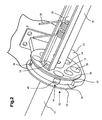
- FIG. 1 is a perspective view of the central portion of a crop pick-up - a so-called pick-up - which is used on balers, loader wagons, rakes or forage harvesters.
- the susceptor comprises a central cylindrical shaft 10 which extends across the width of the susceptor and is journaled at its ends to the housing 8 of the susceptor.
- circular support member 12 with eight evenly around the circumference of the shaft 10 distributed holes 14 are fixed, which extend parallel to the longitudinal axis of the shaft 10.
- bearings 18 are arranged.
- the threads of the screws 16 are screwed into corresponding threads in the ends of U-shaped tine carrier 20, which extend parallel to the shaft 10.
- the tine carrier 20 are rotatably fixed about its longitudinal axis on the support member 12.
- tines 22 are attached, the are made of resilient material and comprise a spiral-shaped portion which is connected to the tine carrier 20 and at the ends of which outwardly extending portions are provided.
- tine carriers 20 arranged on each side of the support member 12, of which only two are shown in the drawing for reasons of clarity.
- the arranged on the left side of the support member 12 tine carrier 20 are opposite to their respective adjacent, arranged on the right side of the support member 12 tine carriers 20 offset by 45 °.
- the prongs 22 extend through slots (not shown in the Figure for clarity) in the housing 8 and are adapted to receive crop material and to convey upwardly when the picker is moved over a field on which the crop is usually located lies in a swath.
- the shaft 10 is coupled to a drive which sets it in rotation.
- the tine holders 20 with the tines 22 are driven via the shaft 10, the support member 12 rotatably connected to the shaft 10 and the bearings 18 so that they rotate about the shaft 10.
- the angular position of the tine carrier 20 relative to the shaft 10 is controlled at the outer ends by means known per se (eccentric controls or cam tracks).
- embodiments with non-controlled tines 22 are also conceivable in which the tine carriers 20 are rigidly fastened to the holding element 12. Then the angular offset attachment of the tine carrier 20 on the two sides of the support member 12 is unnecessary.
- the support member 12 is supported by a bearing member 24 on the housing 8 of the pickup.
- the bearing element 24 comprises two cylindrical rollers 26, the axes of which extend parallel to the longitudinal axis of the shaft 10.
- the rollers 26 are rotatably mounted on the bearing element 24.
- the circumference of the rollers 26 rolls on the circumference of the support member 12.
- the bearing element 24 is fixed or mounted around an axis parallel to the shaft 10 extending pendulously on the housing 8 of the pickup. It can also be a second bearing element the drawn bearing element 24 of the shaft 10 diametrically opposite to the housing 8 are connected.
- the support member 12 and the bearing member 24 allow a central support of the shaft 10 and a relatively small distance of the tine carrier 20 left and right of the support member 12th
- FIG. 2 a second embodiment of the central storage of the pickup is shown. Elements corresponding to the first embodiment are identified by the same reference numerals.
- Storage according to FIG. 2 also includes a support member 12 having a central, axial opening through which the shaft 10 extends. Furthermore, four openings or bores 14 are distributed around this central opening, the axes of which extend parallel to the shaft 10. These bores 14 each receive a bearing 18 for a tine carrier 20.
- the tine carriers 20 on one side of the support member 12 are not mounted at 45 ° to the tine carriers 20 on the other side of the support member 12, but the bores 14 with the supports 18 respectively support the tine carriers 20 on both sides of the support member 12. For the sake of clarity, is in the FIG.
- tine carriers 20 only a tine carrier 20 shown on the right side of the support member 12; however, four tine carriers 20 are provided on each side. It would also be conceivable for the tine carriers 20 to extend through the bores 14. The tine carriers 20 are secured and drivable at their remaining ends in a manner as described above with respect to the embodiment FIG. 1 has been described.
- Each offset by 45 ° to the holes 14 four more circular cylindrical openings 28 are provided in the support member 12. Their centers are further spaced from the shaft 10 than that of the holes 14. The openings 28 have a smaller diameter than the holes 14, but could also have the same or a larger diameter.
- the outer surface of the support member 12 includes a central groove 30 located between two radially projecting flange-like portions 32.
- the openings 28 are arranged such that windows 34 extending from the openings 28 into the groove 30 result.
- the openings 28 are also no through holes, but have their in the FIG. 2 Left marked end faces 36, in which there are central holes 38.
- a roller 40 is rotatably mounted in each of the openings 28, .
- the rollers 40 are connected to the bottoms 36 via ball or other roller bearings and bolts 38 extending through the holes 38.
- the rollers 40 are thus free to rotate in the openings 28 and portions of their outer surfaces extend through the windows 34 into the groove 30.
- a stationary bearing element 24 is connected, screwed in the concrete. Its measured along the longitudinal axis of the shaft 10 width is slightly smaller than that of the groove 30.
- the bearing member 24 extends to the underside of the support member 12 and surrounds the groove 30 by an angular range of about 180 °. It would also be conceivable that the bearing element 24, the support member 12 by a smaller or larger angle range or even completely encloses.
- the extending through the windows 34 portions of the rollers 40 roll on the support member 12 adjacent surface of the bearing member 24 from.
- the bearing member 24 provides the support member 12 in the vertical direction a support.
- the support member 12 is fixed by the bearing member 24 in the axial direction of the shaft 10, since the bearing member 24 extends between the flange-like portions 32.
Landscapes
- Life Sciences & Earth Sciences (AREA)
- Environmental Sciences (AREA)
- Soil Working Implements (AREA)
- Apparatuses For Bulk Treatment Of Fruits And Vegetables And Apparatuses For Preparing Feeds (AREA)
- Outside Dividers And Delivering Mechanisms For Harvesters (AREA)
- Transplanting Machines (AREA)
- Harvester Elements (AREA)
Claims (10)
- Ramasseur pour produits agricoles, comportant un carter (8), un arbre (10), monté dans le carter (8) de manière rotative par rapport à celui-ci et pouvant être entraîné en rotation, des porte-dents (20), qui s'étendent parallèlement à l'arbre (10), des dents (22) fixées sur les porte-dents (20), et comportant un élément de fixation (12), qui est agencé coaxialement à l'arbre (10) et sur lequel sont montés les porte-dents (20), caractérisé en ce que l'élément de fixation (12) est monté de manière rotative sur le carter (8).
- Ramasseur selon la revendication 1, caractérisé en ce que l'élément de fixation (12) est en appui sur le carter (8) au moyen de galets (26, 40) rotatifs.
- Ramasseur selon la revendication 2, caractérisé en ce que des galets (26), assemblés au carter (8) et avec des axes de rotation orientés parallèlement à l'arbre (10), sont en appui sur l'élément de fixation (12).
- Ramasseur selon la revendication 3, caractérisé en ce qu'au moins deux galets (26), en appui sur l'élément de fixation (12), sont montés sur un élément de palier (24), attaché de manière fixe ou oscillante au carter (8).
- Ramasseur selon la revendication 2, caractérisé en ce que des galets (40) sont montés de manière rotative sur l'élément de fixation (12), lesquels roulent sur un élément de palier (24) assemblé au carter (8) ou formé d'un seul tenant avec celui-ci.
- Ramasseur selon la revendication 5, caractérisé en ce que les galets (40) sont agencés à l'intérieur d'orifices (28) de l'élément de fixation (12), et en ce que des parties des galets (40), entrant en contact avec le carter (8) ou l'élément de palier (24), s'étendent vers l'extérieur à travers des fenêtres (34) des orifices (28) dans le sens radial au-dessus de la surface adjacente de l'élément de palier (12).
- Ramasseur selon l'une quelconque des revendications précédentes, caractérisé en ce qu'au moins des parties d'un élément de palier (24), assemblé au carter (8), s'étendent entre des zones (32) de l'élément de fixation (12), entre lesquelles se situe une rainure (30), de telle sorte que l'élément de fixation (12) est fixé dans le sens axial de l'arbre (10) au moyen de l'élément de palier (24).
- Ramasseur selon l'une quelconque des revendications précédentes, caractérisé en ce que les porte-dents (20) sont montés de manière pivotante sur l'élément de fixation (12).
- Ramasseur selon l'une quelconque des revendications précédentes, caractérisé en ce que les porte-dents (20) sont agencés sur les deux côtés de l'élément de fixation (12) et, de préférence, présentent un décalage angulaire entre eux.
- Ramasseur selon l'une quelconque des revendications précédentes, caractérisé en ce que l'élément de fixation (12) est monté sensiblement au milieu sur l'arbre (10).
Applications Claiming Priority (2)
| Application Number | Priority Date | Filing Date | Title |
|---|---|---|---|
| DE10215034A DE10215034A1 (de) | 2002-04-05 | 2002-04-05 | Aufnehmer für landwirtschaftliches Erntegut |
| DE10215034 | 2002-04-05 |
Publications (2)
| Publication Number | Publication Date |
|---|---|
| EP1350423A1 EP1350423A1 (fr) | 2003-10-08 |
| EP1350423B1 true EP1350423B1 (fr) | 2008-03-26 |
Family
ID=27816158
Family Applications (1)
| Application Number | Title | Priority Date | Filing Date |
|---|---|---|---|
| EP03100187A Expired - Lifetime EP1350423B1 (fr) | 2002-04-05 | 2003-01-29 | Ramasseur pour produits agricoles |
Country Status (3)
| Country | Link |
|---|---|
| EP (1) | EP1350423B1 (fr) |
| AT (1) | ATE390041T1 (fr) |
| DE (2) | DE10215034A1 (fr) |
Families Citing this family (4)
| Publication number | Priority date | Publication date | Assignee | Title |
|---|---|---|---|---|
| DE102005020464A1 (de) * | 2005-04-29 | 2006-11-16 | Deere & Company, Moline | Zinkenträgergehäuse, Zinkenträger und Aufnehmer für landwirtschaftliches Erntegut |
| DE102007034924A1 (de) * | 2007-07-24 | 2009-01-29 | Claas Saulgau Gmbh | Aufnahmevorrichtung zum Aufnehmen von am Boden liegenden Erntegut |
| FR2977759B1 (fr) * | 2011-07-13 | 2013-07-19 | Kuhn Sa | Dispositif de ramassage muni de paliers perfectionnes et machine agricole equipee d'un tel dispositif |
| EP4512228A1 (fr) * | 2023-08-22 | 2025-02-26 | Andreas Rahm | Râteau à bande |
Family Cites Families (8)
| Publication number | Priority date | Publication date | Assignee | Title |
|---|---|---|---|---|
| US2388212A (en) * | 1943-08-23 | 1945-10-30 | Hart Carter Co | Pickup |
| DE1159351B (de) * | 1961-04-11 | 1963-12-12 | Massey Ferguson Ltd | Umlaufende Foerdertrommel mit beweglichen Foerderfingern zum Aufnehmen des Gutes undAbgeben an einen nachgeschalteten Foerderer |
| FR1600985A (fr) * | 1968-03-20 | 1970-08-03 | ||
| DD128901B1 (de) * | 1976-12-31 | 1979-12-27 | Guenter John | Aufnehmer fuer am boden liegendes erntegut |
| FR2502455B1 (fr) * | 1981-03-27 | 1985-07-19 | Deere John | Ramasseur pour machines de recolte |
| DD206872A3 (de) * | 1981-12-10 | 1984-02-08 | Georg Scholtissek | Aufnehmer fuer selbstfahrende erntemaschinen grosser arbeitsbreite |
| DE8613011U1 (de) * | 1986-05-13 | 1986-07-17 | Claas Saulgau GmbH, 7968 Saulgau | Breite Aufnahmetrommel für Halmgut |
| US6327840B1 (en) * | 1998-05-05 | 2001-12-11 | Deere & Company | Toothbar and toothbar center support arrangement for baler pickup reel |
-
2002
- 2002-04-05 DE DE10215034A patent/DE10215034A1/de not_active Withdrawn
-
2003
- 2003-01-29 EP EP03100187A patent/EP1350423B1/fr not_active Expired - Lifetime
- 2003-01-29 DE DE50309442T patent/DE50309442D1/de not_active Expired - Lifetime
- 2003-01-29 AT AT03100187T patent/ATE390041T1/de not_active IP Right Cessation
Also Published As
| Publication number | Publication date |
|---|---|
| DE50309442D1 (de) | 2008-05-08 |
| ATE390041T1 (de) | 2008-04-15 |
| DE10215034A1 (de) | 2003-11-13 |
| EP1350423A1 (fr) | 2003-10-08 |
Similar Documents
| Publication | Publication Date | Title |
|---|---|---|
| DE102007015101B4 (de) | Gutaufnehmer mit einer von der Drehrichtung abhängigen Stellung der Zinkenträger | |
| EP1048199B1 (fr) | Rabatteur pour machine de récolte | |
| EP0903077A1 (fr) | Ramasseur por recoltes | |
| DD237464A5 (de) | Maehdrescher mit einer nach dem axialflussprinzip arbeitenden trennvorrichtung | |
| DE19861245B4 (de) | Mähdrescher mit einem Rotationsförderer | |
| EP2614698B2 (fr) | Faucheuse | |
| DE2736104A1 (de) | Haspelanordnung fuer erntemaschinen | |
| DE68902361T2 (de) | Heuwerbungsmaschine mit einem rechrad. | |
| EP3326448A1 (fr) | Machine agricole comprenant un dispositif de ramassage | |
| EP2342967A1 (fr) | Récepteur de biens doté d'une protection d'enroulement | |
| DE19811449C1 (de) | Fördereinrichtung für Erntemaschinen | |
| DE10042499A1 (de) | Rotationsförderer mit Fingern | |
| EP2147590B1 (fr) | Dispositif de réception de marchandises dont la position du porte-dents dépend du sens de rotation | |
| DE2001386A1 (de) | Vorrichtung zum Verteilen und Lockern des aus der Dreschvorrichtung eines Maehdreschers anfallenden Gutes | |
| EP1417879A1 (fr) | Ramasseur pour produits agricoles | |
| DE1507341B2 (de) | Schleppergezogene heuwerbungsmaschine | |
| EP1350423A1 (fr) | Ramasseur pour produits agricoles | |
| DE3621995A1 (de) | Aufsammler fuer halmguterntemaschinen | |
| DE3211177A1 (de) | Lockerungs- und verteilvorrichtung an strohschuettlern | |
| EP1357784B1 (fr) | Elements d'evacuation pour dispositifs de coupe et de transport d'un systeme de coupe | |
| EP3058805A1 (fr) | Faneuse | |
| DE3215974C2 (de) | Ladewagen | |
| EP3178310B1 (fr) | Dispositif de réception d'un engin agricole | |
| DE3119335A1 (de) | "ladewagen" | |
| DE1159351B (de) | Umlaufende Foerdertrommel mit beweglichen Foerderfingern zum Aufnehmen des Gutes undAbgeben an einen nachgeschalteten Foerderer |
Legal Events
| Date | Code | Title | Description |
|---|---|---|---|
| PUAI | Public reference made under article 153(3) epc to a published international application that has entered the european phase |
Free format text: ORIGINAL CODE: 0009012 |
|
| AK | Designated contracting states |
Kind code of ref document: A1 Designated state(s): AT BE BG CH CY CZ DE DK EE ES FI FR GB GR HU IE IT LI LU MC NL PT SE SI SK TR |
|
| AX | Request for extension of the european patent |
Extension state: AL LT LV MK RO |
|
| 17P | Request for examination filed |
Effective date: 20040326 |
|
| 17Q | First examination report despatched |
Effective date: 20040506 |
|
| AKX | Designation fees paid |
Designated state(s): AT BE BG CH CY CZ DE DK EE ES FI FR GB GR HU IE IT LI LU MC NL PT SE SI SK TR |
|
| GRAC | Information related to communication of intention to grant a patent modified |
Free format text: ORIGINAL CODE: EPIDOSCIGR1 |
|
| GRAP | Despatch of communication of intention to grant a patent |
Free format text: ORIGINAL CODE: EPIDOSNIGR1 |
|
| GRAS | Grant fee paid |
Free format text: ORIGINAL CODE: EPIDOSNIGR3 |
|
| GRAA | (expected) grant |
Free format text: ORIGINAL CODE: 0009210 |
|
| AK | Designated contracting states |
Kind code of ref document: B1 Designated state(s): AT BE BG CH CY CZ DE DK EE ES FI FR GB GR HU IE IT LI LU MC NL PT SE SI SK TR |
|
| REG | Reference to a national code |
Ref country code: GB Ref legal event code: FG4D Free format text: NOT ENGLISH |
|
| REG | Reference to a national code |
Ref country code: IE Ref legal event code: FG4D Free format text: LANGUAGE OF EP DOCUMENT: GERMAN Ref country code: CH Ref legal event code: EP |
|
| REF | Corresponds to: |
Ref document number: 50309442 Country of ref document: DE Date of ref document: 20080508 Kind code of ref document: P |
|
| PG25 | Lapsed in a contracting state [announced via postgrant information from national office to epo] |
Ref country code: FI Free format text: LAPSE BECAUSE OF FAILURE TO SUBMIT A TRANSLATION OF THE DESCRIPTION OR TO PAY THE FEE WITHIN THE PRESCRIBED TIME-LIMIT Effective date: 20080326 |
|
| NLV1 | Nl: lapsed or annulled due to failure to fulfill the requirements of art. 29p and 29m of the patents act | ||
| PG25 | Lapsed in a contracting state [announced via postgrant information from national office to epo] |
Ref country code: SI Free format text: LAPSE BECAUSE OF FAILURE TO SUBMIT A TRANSLATION OF THE DESCRIPTION OR TO PAY THE FEE WITHIN THE PRESCRIBED TIME-LIMIT Effective date: 20080326 |
|
| REG | Reference to a national code |
Ref country code: IE Ref legal event code: FD4D |
|
| PG25 | Lapsed in a contracting state [announced via postgrant information from national office to epo] |
Ref country code: PT Free format text: LAPSE BECAUSE OF FAILURE TO SUBMIT A TRANSLATION OF THE DESCRIPTION OR TO PAY THE FEE WITHIN THE PRESCRIBED TIME-LIMIT Effective date: 20080901 Ref country code: ES Free format text: LAPSE BECAUSE OF FAILURE TO SUBMIT A TRANSLATION OF THE DESCRIPTION OR TO PAY THE FEE WITHIN THE PRESCRIBED TIME-LIMIT Effective date: 20080707 Ref country code: CZ Free format text: LAPSE BECAUSE OF FAILURE TO SUBMIT A TRANSLATION OF THE DESCRIPTION OR TO PAY THE FEE WITHIN THE PRESCRIBED TIME-LIMIT Effective date: 20080326 Ref country code: SE Free format text: LAPSE BECAUSE OF FAILURE TO SUBMIT A TRANSLATION OF THE DESCRIPTION OR TO PAY THE FEE WITHIN THE PRESCRIBED TIME-LIMIT Effective date: 20080626 Ref country code: SK Free format text: LAPSE BECAUSE OF FAILURE TO SUBMIT A TRANSLATION OF THE DESCRIPTION OR TO PAY THE FEE WITHIN THE PRESCRIBED TIME-LIMIT Effective date: 20080326 |
|
| ET | Fr: translation filed | ||
| PG25 | Lapsed in a contracting state [announced via postgrant information from national office to epo] |
Ref country code: NL Free format text: LAPSE BECAUSE OF FAILURE TO SUBMIT A TRANSLATION OF THE DESCRIPTION OR TO PAY THE FEE WITHIN THE PRESCRIBED TIME-LIMIT Effective date: 20080326 |
|
| PG25 | Lapsed in a contracting state [announced via postgrant information from national office to epo] |
Ref country code: IE Free format text: LAPSE BECAUSE OF FAILURE TO SUBMIT A TRANSLATION OF THE DESCRIPTION OR TO PAY THE FEE WITHIN THE PRESCRIBED TIME-LIMIT Effective date: 20080326 Ref country code: DK Free format text: LAPSE BECAUSE OF FAILURE TO SUBMIT A TRANSLATION OF THE DESCRIPTION OR TO PAY THE FEE WITHIN THE PRESCRIBED TIME-LIMIT Effective date: 20080326 |
|
| PLBE | No opposition filed within time limit |
Free format text: ORIGINAL CODE: 0009261 |
|
| STAA | Information on the status of an ep patent application or granted ep patent |
Free format text: STATUS: NO OPPOSITION FILED WITHIN TIME LIMIT |
|
| 26N | No opposition filed |
Effective date: 20081230 |
|
| PG25 | Lapsed in a contracting state [announced via postgrant information from national office to epo] |
Ref country code: EE Free format text: LAPSE BECAUSE OF FAILURE TO SUBMIT A TRANSLATION OF THE DESCRIPTION OR TO PAY THE FEE WITHIN THE PRESCRIBED TIME-LIMIT Effective date: 20080326 Ref country code: BG Free format text: LAPSE BECAUSE OF FAILURE TO SUBMIT A TRANSLATION OF THE DESCRIPTION OR TO PAY THE FEE WITHIN THE PRESCRIBED TIME-LIMIT Effective date: 20080626 |
|
| PG25 | Lapsed in a contracting state [announced via postgrant information from national office to epo] |
Ref country code: MC Free format text: LAPSE BECAUSE OF NON-PAYMENT OF DUE FEES Effective date: 20090131 Ref country code: IT Free format text: LAPSE BECAUSE OF FAILURE TO SUBMIT A TRANSLATION OF THE DESCRIPTION OR TO PAY THE FEE WITHIN THE PRESCRIBED TIME-LIMIT Effective date: 20080326 |
|
| REG | Reference to a national code |
Ref country code: CH Ref legal event code: PL |
|
| GBPC | Gb: european patent ceased through non-payment of renewal fee |
Effective date: 20090129 |
|
| PG25 | Lapsed in a contracting state [announced via postgrant information from national office to epo] |
Ref country code: CY Free format text: LAPSE BECAUSE OF FAILURE TO SUBMIT A TRANSLATION OF THE DESCRIPTION OR TO PAY THE FEE WITHIN THE PRESCRIBED TIME-LIMIT Effective date: 20080326 |
|
| PG25 | Lapsed in a contracting state [announced via postgrant information from national office to epo] |
Ref country code: LI Free format text: LAPSE BECAUSE OF NON-PAYMENT OF DUE FEES Effective date: 20090131 Ref country code: CH Free format text: LAPSE BECAUSE OF NON-PAYMENT OF DUE FEES Effective date: 20090131 |
|
| PG25 | Lapsed in a contracting state [announced via postgrant information from national office to epo] |
Ref country code: GB Free format text: LAPSE BECAUSE OF NON-PAYMENT OF DUE FEES Effective date: 20090129 |
|
| PG25 | Lapsed in a contracting state [announced via postgrant information from national office to epo] |
Ref country code: BE Free format text: LAPSE BECAUSE OF NON-PAYMENT OF DUE FEES Effective date: 20090131 |
|
| PG25 | Lapsed in a contracting state [announced via postgrant information from national office to epo] |
Ref country code: AT Free format text: LAPSE BECAUSE OF NON-PAYMENT OF DUE FEES Effective date: 20090129 |
|
| PG25 | Lapsed in a contracting state [announced via postgrant information from national office to epo] |
Ref country code: GR Free format text: LAPSE BECAUSE OF FAILURE TO SUBMIT A TRANSLATION OF THE DESCRIPTION OR TO PAY THE FEE WITHIN THE PRESCRIBED TIME-LIMIT Effective date: 20080627 |
|
| PG25 | Lapsed in a contracting state [announced via postgrant information from national office to epo] |
Ref country code: LU Free format text: LAPSE BECAUSE OF NON-PAYMENT OF DUE FEES Effective date: 20090129 |
|
| PG25 | Lapsed in a contracting state [announced via postgrant information from national office to epo] |
Ref country code: HU Free format text: LAPSE BECAUSE OF FAILURE TO SUBMIT A TRANSLATION OF THE DESCRIPTION OR TO PAY THE FEE WITHIN THE PRESCRIBED TIME-LIMIT Effective date: 20080927 |
|
| PG25 | Lapsed in a contracting state [announced via postgrant information from national office to epo] |
Ref country code: TR Free format text: LAPSE BECAUSE OF FAILURE TO SUBMIT A TRANSLATION OF THE DESCRIPTION OR TO PAY THE FEE WITHIN THE PRESCRIBED TIME-LIMIT Effective date: 20080326 |
|
| REG | Reference to a national code |
Ref country code: FR Ref legal event code: PLFP Year of fee payment: 14 |
|
| REG | Reference to a national code |
Ref country code: FR Ref legal event code: PLFP Year of fee payment: 15 |
|
| REG | Reference to a national code |
Ref country code: FR Ref legal event code: PLFP Year of fee payment: 16 |
|
| PGFP | Annual fee paid to national office [announced via postgrant information from national office to epo] |
Ref country code: DE Payment date: 20201221 Year of fee payment: 19 |
|
| PGFP | Annual fee paid to national office [announced via postgrant information from national office to epo] |
Ref country code: FR Payment date: 20220125 Year of fee payment: 20 |
|
| REG | Reference to a national code |
Ref country code: DE Ref legal event code: R119 Ref document number: 50309442 Country of ref document: DE |
|
| PG25 | Lapsed in a contracting state [announced via postgrant information from national office to epo] |
Ref country code: DE Free format text: LAPSE BECAUSE OF NON-PAYMENT OF DUE FEES Effective date: 20220802 |