EP1350666A1 - Ensemble circuit et méthode pour alimentation et récupération électrique d'une ligne de contact - Google Patents
Ensemble circuit et méthode pour alimentation et récupération électrique d'une ligne de contact Download PDFInfo
- Publication number
- EP1350666A1 EP1350666A1 EP02007785A EP02007785A EP1350666A1 EP 1350666 A1 EP1350666 A1 EP 1350666A1 EP 02007785 A EP02007785 A EP 02007785A EP 02007785 A EP02007785 A EP 02007785A EP 1350666 A1 EP1350666 A1 EP 1350666A1
- Authority
- EP
- European Patent Office
- Prior art keywords
- inverter
- circuit arrangement
- transformer
- voltage
- diode rectifier
- Prior art date
- Legal status (The legal status is an assumption and is not a legal conclusion. Google has not performed a legal analysis and makes no representation as to the accuracy of the status listed.)
- Granted
Links
- 238000000034 method Methods 0.000 title claims abstract description 6
- 238000011084 recovery Methods 0.000 title description 5
- 239000003990 capacitor Substances 0.000 claims description 10
- 238000004804 winding Methods 0.000 claims description 8
- 230000008929 regeneration Effects 0.000 claims description 6
- 238000011069 regeneration method Methods 0.000 claims description 6
- 230000005611 electricity Effects 0.000 claims 1
- 230000008901 benefit Effects 0.000 description 5
- 239000004065 semiconductor Substances 0.000 description 4
- 230000001133 acceleration Effects 0.000 description 3
- 230000001172 regenerating effect Effects 0.000 description 3
- 239000000654 additive Substances 0.000 description 2
- 230000000996 additive effect Effects 0.000 description 2
- 230000001627 detrimental effect Effects 0.000 description 2
- 239000011159 matrix material Substances 0.000 description 2
- 230000004913 activation Effects 0.000 description 1
- 238000010276 construction Methods 0.000 description 1
- 238000005516 engineering process Methods 0.000 description 1
- 230000001771 impaired effect Effects 0.000 description 1
- 230000006872 improvement Effects 0.000 description 1
- 230000008569 process Effects 0.000 description 1
- 230000001105 regulatory effect Effects 0.000 description 1
- 230000009466 transformation Effects 0.000 description 1
Images




Classifications
-
- B—PERFORMING OPERATIONS; TRANSPORTING
- B60—VEHICLES IN GENERAL
- B60M—POWER SUPPLY LINES, AND DEVICES ALONG RAILS, FOR ELECTRICALLY- PROPELLED VEHICLES
- B60M3/00—Feeding power to supply lines in contact with collector on vehicles; Arrangements for consuming regenerative power
- B60M3/06—Arrangements for consuming regenerative power
Definitions
- the invention describes a circuit arrangement for feeding current into a Catenary to power electrically powered vehicles from one in the Rule 3-phase AC supply network and for energy recovery the catenary into the AC supply network and a method for activation this circuit arrangement.
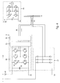
- Contact lines are known, preferably designed as overhead lines, for the energy supply of rail-bound vehicles, such as trams, or also non-rail-bound vehicles, such as so-called trolley buses. Such overhead lines are advantageously designed as single-phase direct current lines. These overhead contact lines are fed according to the state of the art from a mostly three-phase medium-voltage network with a frequency of 50Hz or 60Hz and voltages in the range of 10kV. 1a shows an infeed into a catenary according to the prior art.
- the primary side of a transformer (30) is connected to the AC power supply network (10).
- the secondary side of the transformer is connected to a 3-phase diode rectifier (40) via chokes (32), which can also be part of the transformer itself.
- a pulsating DC voltage U s of, for example, 750 V is generated in the overhead contact line, fluctuations of ⁇ 20% corresponding to the prior art.
- This diode rectifier is connected directly to the catenary.
- the state-of-the-art technology used to power the overhead lines Diode rectifiers are characterized by their simple and robust construction. At the same time, these are extremely cheap. These criteria are necessary because the Contact lines, e.g. of trams, often in sections of the order of kilometers can be divided, each of these sections having its own decentralized energy supply having. To keep costs down and secure energy supply too To ensure this must be designed robust and inexpensive.
- Power supplies as shown in FIG. 1a and described above are designed, for example, for a nominal power W D to be transmitted of 1 MW, an overload capacity up to three times the nominal power also corresponding to the prior art.
- the current voltage UF of the catenary drops due to Voltage drops in the diode rectifier, the catenary itself and in the vehicle a few percent.
- the object of the present invention is to provide a circuit arrangement and a method to introduce their control, the energy from a supply network into the catenary for electrically powered vehicles, as well as the braking energy of the vehicles the overhead line feeds back into the supply network and into existing ones Supply circuit arrangement can be integrated, the functioning of which is not impaired and dimensioned such that the braking energy in substantial parts the supply network can be fed back.
- the basic idea of the invention is the circuit arrangement for feeding current into a Leaving overhead contact line unchanged according to the state of the art as well as a parallel one To provide circuitry for feeding back into the supply network, this Circuit arrangement for feedback less than half, preferably a quarter, of Has nominal power of the diode rectifier.
- This circuit arrangement for Regeneration consists of an inverter and an additional diode, whose anode is connected to the contact line and its cathode with the intermediate circuit of the Inverter is connected.
- the inverter has a maximum capacity of half that Nominal performance of the diode rectifier corresponds, since as described above in Average about a quarter of the energy consumed during a driving cycle from the Vehicle is fed back into the catenary and only this energy for feedback the supply network is available.
- the inverter Depending on the proportion to which the accruing Braking energy in the overhead contact line is to be fed back into the supply network To design the inverter accordingly:
- the task of the additional diode is to decouple the intermediate circuit of the Inverter and the catenary. Because on the catenary during standstill or a pulsating direct current is applied while a vehicle is traveling there, would connect the DC link directly to the overhead contact line pulsating direct current also on the intermediate circuit and thus on its capacitors issue. However, this pulsating direct current is the lifespan of the DC link capacitors detrimental, since they are pulsating with the frequency DC voltage would be partially charged and discharged again permanently.
- the driving cycle is a Vehicle divided into four areas: standstill, acceleration phase, driving with constant Speed and braking phase. There is no flow when the vehicle is at a standstill Energy, neither from nor into the supply network.
- the necessary flow flows during the acceleration phase and while driving Energy through the diode rectifier from the supply network into the overhead line.
- the Regenerative unit is inactive.
- the voltage in the supply network fluctuates within the specified tolerances of approx. 20% around the nominal value.
- the diode rectifier is inactive because the voltage in the Catenary is higher than the voltage that the diode rectifier could supply.
- the higher-level control device determines that the value of the voltage in the catenary, the is increased by voltage fed back from the vehicle, the current from the Supply network measured in front of the rectifier and with a correction factor provided (rectified) exceeded by a defined switch-on threshold, the Energy is fed back from the overhead contact line into the supply line using the Inverter started. This recovery ends as soon as the above Comparison falls below a switch-off threshold. It concerns the arrival or Switch-off values are therefore dynamic values, which can only be achieved by the described comparison be formed.
- the inverter can perform other tasks, such as the Reactive power compensation for the supply network or an improvement in the Distortion factor of the supply network.
- Fig. 3 shows schematically the voltage curve in the catenary during a Driving cycle.
- FIG. 4 shows an inventive circuit arrangement with a plurality of 3-phases arranged in parallel Inverter cells.
- FIG. 5 shows an inventive circuit arrangement with two 3-phase arranged in series Inverter cells.
- FIG. 6 shows an inventive circuit arrangement with a plurality arranged in a matrix 3-phase inverter cells.
- Fig. 2 shows an inventive circuit arrangement consisting of a (not drawn) control unit, a 3-phase supply network (10), an overhead line (20), a transformer (30), a diode rectifier (40), an inverter (5, 50) and a diode (60).
- the transformer is on the primary side with the AC power supply network (10) connected.
- the transformer is on the secondary side connected to the input of the diode rectifier (40).
- the exit of the Diode rectifier is connected directly to the contact line (20).
- the circuit arrangement serves for energy supply the catenary (20).
- the inverter For the recovery of energy from the contact line (20) into the supply network (10) Catenary connected to an inverter (5, 50) via a diode.
- the inverter consists of one DC link capacitor (52) and three half-bridge circuits, one for each phase. This Half bridges in turn consist of two power semiconductor switches with anti-parallel switched freewheeling diodes.
- the circuit breakers are IGBTs according to the state of the art (insulated gate bipolar transistors).
- the center tap of each half-bridge is via a throttle (38) connected to the secondary side of the transformer (30).
- the transformer serves thus both for the transformation of the tensions of the supply as well as the Recovery.
- the diode (60) decouples the intermediate circuit and the contact line (20) in order not to apply voltage fluctuations to the contact line capacitor (52).
- the intermediate circuit is thus charged to the current peak value ⁇ F of the overhead line voltage U F.
- FIG. 3 schematically shows the voltage curve in the catenary during a driving cycle when using an inventive circuit arrangement according to FIG. 2, the parameters also following those in the description of FIG. 2.
- the time course is plotted in arbitrary units on the abscissa, the voltage in volts is plotted on the ordinate.
- U F shows the voltage curve in the catenary.
- a braking phase is shown in the period t B to t D , the braking not leading to the vehicle coming to a standstill.
- the voltage in the overhead contact line U F increases as a result of the feedback of braking energy from the vehicle into the overhead contact line and via the diode (60) into the intermediate circuit of the inverter. According to the prior art, the voltage would rise up to a maximum value U max (dashed line), after which the braking energy would be dissipated in a braking resistor.
- the voltage in the overhead contact line also rises, however, at time t R , regulated by a higher-level control, the inverter begins to feed energy back from the overhead contact line into the supply network from a dynamic voltage value U Rstart .
- the value of the dynamic switching threshold U Rstart is determined as follows:
- the value of the voltage in the DC link (identical to ⁇ F ) is compared with the calculated value U G of the DC voltage supply.
- the higher-level controller ends the regeneration by means of the inverter.
- the voltage U F again shows the known pulsating course from the time t D after a residual energy has been consumed.
- FIG. 4 shows an inventive circuit arrangement for higher powers of the inverter (5) compared to FIG. 2.
- a plurality, here three, identical 3-phase inverters (50), so-called cells, are advantageously arranged in parallel.
- the other parameters are identical to those from Fig. 2.
- the transformer (30), the Diode rectifier (40) and the diode (60) are adapted to the higher power, However, their functionality does not differ from that of FIG. 2.
- the three 3-phase Inverter cells are connected in parallel, with each inverter cell (50) the center taps of the half bridges are connected to each other for the respective phase.
- a further advantageous embodiment of the parallel arrangement is achieved in that a cell does not only consist of the intermediate circuit capacitor and the three half bridges, but the cell (50a) a unit of diode (60), intermediate circuit capacitor (52) the three Half bridges and the chokes (38) associated with the respective center tap.
- the advantage here is that, for higher outputs, complete functional blocks (50a) can be strung together without having to re-dimension diodes or chokes.
- FIG. 5 shows an inventive circuit arrangement for a higher voltage in the overhead contact line compared to FIG. 2, as is used, for example, in commuter trains.
- no arrangement identical to FIG. 2 with higher-blocking power semiconductor components of the voltage class 3300V is used, but advantageously a plurality, here two, identical, three-phase inverter cells (50), with standard semiconductor components of the voltage class 1700V, are arranged in series.
- the other parameters are identical to those from FIG. 2, with the values for the dynamic switching thresholds at the beginning or end of the feedback to a cell or whose DC link voltage are related.
- the transformer (30) with the chokes (32) is in this circuit arrangement provided exclusively for supplying the diode rectifier (40).
- the inverter here consists of a serial arrangement of the known cells (50).
- the voltage of the catenary is divided between the two cells (50).
- This has the Advantage that cells with line semiconductor components according to the prior art can use that in very good quality for the voltage classes 1200V and 1700V are available.
- the center taps of the individual half bridges are each inverter cell with the secondary windings of a transformer (34) via intermediate chokes (38) connected. These secondary windings are designed in such a way that those in the respective Half-bridge of an inverter cell generated currents and voltages using the Primary winding can be fed back into the supply network.
- the functionality of the diode (60) does not differ from that from FIG. 2.
- FIG. 6 shows an inventive circuit arrangement for, in comparison to FIG. 2, higher voltage in the catenary and a higher power of the inverter.
- a plurality, here six, identical 3-phase inverter cells (50) are advantageously arranged in a matrix.
- This circuit arrangement is a combination of the circuit arrangements shown in FIGS. 4 and 5 with those there Advantages described and the same functionality as described in Fig. 5.
Landscapes
- Engineering & Computer Science (AREA)
- Mechanical Engineering (AREA)
- Electric Propulsion And Braking For Vehicles (AREA)
- Keying Circuit Devices (AREA)
- Remote Monitoring And Control Of Power-Distribution Networks (AREA)
- Supply And Distribution Of Alternating Current (AREA)
- Emergency Protection Circuit Devices (AREA)
Priority Applications (3)
| Application Number | Priority Date | Filing Date | Title |
|---|---|---|---|
| DE50205492T DE50205492D1 (de) | 2002-04-06 | 2002-04-06 | Schaltungsanordnung und Verfahren zur Stromeinspeisung in eine und Rückspeisung aus einer Fahrleitung |
| AT02007785T ATE314946T1 (de) | 2002-04-06 | 2002-04-06 | Schaltungsanordnung und verfahren zur stromeinspeisung in eine und rückspeisung aus einer fahrleitung |
| EP02007785A EP1350666B1 (fr) | 2002-04-06 | 2002-04-06 | Ensemble circuit et méthode pour alimentation et récupération électrique d'une ligne de contact |
Applications Claiming Priority (1)
| Application Number | Priority Date | Filing Date | Title |
|---|---|---|---|
| EP02007785A EP1350666B1 (fr) | 2002-04-06 | 2002-04-06 | Ensemble circuit et méthode pour alimentation et récupération électrique d'une ligne de contact |
Publications (2)
| Publication Number | Publication Date |
|---|---|
| EP1350666A1 true EP1350666A1 (fr) | 2003-10-08 |
| EP1350666B1 EP1350666B1 (fr) | 2006-01-04 |
Family
ID=27838083
Family Applications (1)
| Application Number | Title | Priority Date | Filing Date |
|---|---|---|---|
| EP02007785A Expired - Lifetime EP1350666B1 (fr) | 2002-04-06 | 2002-04-06 | Ensemble circuit et méthode pour alimentation et récupération électrique d'une ligne de contact |
Country Status (3)
| Country | Link |
|---|---|
| EP (1) | EP1350666B1 (fr) |
| AT (1) | ATE314946T1 (fr) |
| DE (1) | DE50205492D1 (fr) |
Cited By (11)
| Publication number | Priority date | Publication date | Assignee | Title |
|---|---|---|---|---|
| WO2006107807A3 (fr) * | 2005-04-04 | 2007-10-25 | Delphi Tech Inc | Vehicule elctrique a systeme apu a usages multiples |
| EP1985490A1 (fr) * | 2007-04-25 | 2008-10-29 | Alstom Transport S.A. | Système, sous-station et procédé de récupération de l'énergie de freinage de véhicules ferroviaires, véhicules ferroviaires pour ce système. |
| ES2334628A1 (es) * | 2008-09-11 | 2010-03-12 | Ingeteam Technology, S.A | Dispositivo y procedimiento de control para recuperacion de energia cinetica en sistemas ferroviarios. |
| WO2011049661A3 (fr) * | 2009-10-23 | 2012-03-08 | Siemens Industry, Inc. | Système et procédé de réinjection d'énergie de ralentissement dans un tombereau minier électrique de type trolley |
| RU2509667C1 (ru) * | 2012-09-18 | 2014-03-20 | Владимир Евдокимович Осипов | Преобразовательная подстанция транспорта на электрической тяге |
| CN103895534A (zh) * | 2014-02-28 | 2014-07-02 | 株洲变流技术国家工程研究中心有限公司 | 基于模块化多电平换流器的双流制牵引供电系统 |
| EP3032728A1 (fr) * | 2014-12-12 | 2016-06-15 | ABB Technology AG | Agencement de circuit |
| EP3045343A1 (fr) * | 2015-01-16 | 2016-07-20 | ALSTOM Transport Technologies | Convertisseur d'alimentation réseau et/ou de sous-station de récupération de l'énergie de freinage |
| US10286787B2 (en) | 2013-09-27 | 2019-05-14 | Siemens Industry, Inc. | System and method for all electrical operation of a mining haul truck |
| CN111347942A (zh) * | 2018-12-21 | 2020-06-30 | 西安许继电力电子技术有限公司 | 一种牵引供电网及牵引供电系统 |
| EP3678274A4 (fr) * | 2017-10-23 | 2021-05-26 | CRRC Zhuzhou Electric Locomotive Research Institute Co., Ltd. | Système d'alimentation en puissance de traction et appareil de rétroaction d'énergie associé |
Citations (3)
| Publication number | Priority date | Publication date | Assignee | Title |
|---|---|---|---|---|
| FR2316773A1 (fr) * | 1975-07-04 | 1977-01-28 | Acec | Reseau a courant electrique continu |
| FR2417408A1 (fr) * | 1978-02-21 | 1979-09-14 | Jeumont Schneider | Equipement d'alimentation et de recuperation de courant continu pour materiel de traction electrique |
| JPH11286229A (ja) * | 1998-04-02 | 1999-10-19 | Fuji Electric Co Ltd | 電力回生インバータ装置 |
-
2002
- 2002-04-06 DE DE50205492T patent/DE50205492D1/de not_active Expired - Lifetime
- 2002-04-06 AT AT02007785T patent/ATE314946T1/de active
- 2002-04-06 EP EP02007785A patent/EP1350666B1/fr not_active Expired - Lifetime
Patent Citations (3)
| Publication number | Priority date | Publication date | Assignee | Title |
|---|---|---|---|---|
| FR2316773A1 (fr) * | 1975-07-04 | 1977-01-28 | Acec | Reseau a courant electrique continu |
| FR2417408A1 (fr) * | 1978-02-21 | 1979-09-14 | Jeumont Schneider | Equipement d'alimentation et de recuperation de courant continu pour materiel de traction electrique |
| JPH11286229A (ja) * | 1998-04-02 | 1999-10-19 | Fuji Electric Co Ltd | 電力回生インバータ装置 |
Cited By (21)
| Publication number | Priority date | Publication date | Assignee | Title |
|---|---|---|---|---|
| WO2006107807A3 (fr) * | 2005-04-04 | 2007-10-25 | Delphi Tech Inc | Vehicule elctrique a systeme apu a usages multiples |
| EP1985490A1 (fr) * | 2007-04-25 | 2008-10-29 | Alstom Transport S.A. | Système, sous-station et procédé de récupération de l'énergie de freinage de véhicules ferroviaires, véhicules ferroviaires pour ce système. |
| FR2915435A1 (fr) * | 2007-04-25 | 2008-10-31 | Alstom Transport Sa | Systeme, sous-station et procede de recuperation de l'energie de freinage de vehicules ferroviaires, vehicules ferroviaires pour ce systeme. |
| TWI408070B (zh) * | 2007-04-25 | 2013-09-11 | Alstom Transport Sa | 軌道車輛之煞車能量回復系統,變電所與方法及用於此系統之軌道車輛 |
| ES2334628A1 (es) * | 2008-09-11 | 2010-03-12 | Ingeteam Technology, S.A | Dispositivo y procedimiento de control para recuperacion de energia cinetica en sistemas ferroviarios. |
| WO2010029203A1 (fr) * | 2008-09-11 | 2010-03-18 | Ingeteam Technology, S.A. | Dispositif et procédé de contrôle pour la récupération d'énergie cinétique dans des systèmes ferroviaires |
| ES2334628B1 (es) * | 2008-09-11 | 2011-01-07 | Ingeteam Technology, S.A | Dispositivo y procedimiento de control para recuperacion de energia cinetica en sistemas ferroviarios. |
| WO2011049661A3 (fr) * | 2009-10-23 | 2012-03-08 | Siemens Industry, Inc. | Système et procédé de réinjection d'énergie de ralentissement dans un tombereau minier électrique de type trolley |
| US8550007B2 (en) | 2009-10-23 | 2013-10-08 | Siemens Industry, Inc. | System and method for reinjection of retard energy in a trolley-based electric mining haul truck |
| US8550008B2 (en) | 2009-10-23 | 2013-10-08 | Siemens Industry, Inc. | System and method for reinjection of retard energy in a trolley-based electric mining haul truck |
| RU2509667C1 (ru) * | 2012-09-18 | 2014-03-20 | Владимир Евдокимович Осипов | Преобразовательная подстанция транспорта на электрической тяге |
| US10286787B2 (en) | 2013-09-27 | 2019-05-14 | Siemens Industry, Inc. | System and method for all electrical operation of a mining haul truck |
| CN103895534A (zh) * | 2014-02-28 | 2014-07-02 | 株洲变流技术国家工程研究中心有限公司 | 基于模块化多电平换流器的双流制牵引供电系统 |
| CN103895534B (zh) * | 2014-02-28 | 2015-03-25 | 株洲变流技术国家工程研究中心有限公司 | 基于模块化多电平换流器的双流制牵引供电系统 |
| EP3032728A1 (fr) * | 2014-12-12 | 2016-06-15 | ABB Technology AG | Agencement de circuit |
| EP3045343A1 (fr) * | 2015-01-16 | 2016-07-20 | ALSTOM Transport Technologies | Convertisseur d'alimentation réseau et/ou de sous-station de récupération de l'énergie de freinage |
| FR3031849A1 (fr) * | 2015-01-16 | 2016-07-22 | Alstom Transp Tech | Convertisseur d'alimentation reseau et/ou de sous-station de recuperation de l'energie de freinage |
| CN105811797A (zh) * | 2015-01-16 | 2016-07-27 | 阿尔斯通运输科技公司 | 对制动能量进行回收的电馈线和/或变电站的换流器 |
| US10554117B2 (en) | 2015-01-16 | 2020-02-04 | Alstom Transport Technologies | Convertor for electric feeder and/or substation for recuperating the braking energy |
| EP3678274A4 (fr) * | 2017-10-23 | 2021-05-26 | CRRC Zhuzhou Electric Locomotive Research Institute Co., Ltd. | Système d'alimentation en puissance de traction et appareil de rétroaction d'énergie associé |
| CN111347942A (zh) * | 2018-12-21 | 2020-06-30 | 西安许继电力电子技术有限公司 | 一种牵引供电网及牵引供电系统 |
Also Published As
| Publication number | Publication date |
|---|---|
| EP1350666B1 (fr) | 2006-01-04 |
| ATE314946T1 (de) | 2006-02-15 |
| DE50205492D1 (de) | 2006-03-30 |
Similar Documents
| Publication | Publication Date | Title |
|---|---|---|
| DE69519984T2 (de) | Steuerungssystem für elektrische Fahrzeuge | |
| EP2611643B1 (fr) | Système d'alimentation en énergie électrique destiné à des dispositifs d'entraînement de véhicules ferroviaires | |
| DE102018221519B4 (de) | Fahrzeugseitige Ladevorrichtung | |
| DE102008007658A1 (de) | Statischer Umformer | |
| EP3023291A1 (fr) | Système de convertisseur destiné à l'entraînement électrique d'un véhicule ferroviaire | |
| DE102012209071A1 (de) | Vorrichtung für ein elektrisch angetriebenes Schienenfahrzeug | |
| EP2586646B1 (fr) | Dispositif électrique d'alimentation en énergie pour dispositifs d'entraînement destiné au fonctionnement d'un véhicule sur rail sur des réseaux d'alimentation électriques | |
| EP1350666B1 (fr) | Ensemble circuit et méthode pour alimentation et récupération électrique d'une ligne de contact | |
| DE102011080058B4 (de) | Leistungselektronikgerät, insbesondere zur Verwendung in einem Kraftfahrzeug | |
| EP3290254A1 (fr) | Convertisseur de reseau de bord bidirectionnel et son procede de fonctionnement | |
| EP0904973A2 (fr) | Méthode de fonctionnement pour un système de courant d'un vehicule ferroviaire | |
| WO2023006253A1 (fr) | Alimentation électrique pour un véhicule ferroviaire présentant une batterie de traction | |
| DE69625456T2 (de) | Steuereinrichtung für ein Elekrofahrzeug | |
| DD261485A3 (de) | Schaltungsanordnung zur energieversorgung von fahrnetzen fuer elektrische gleichstromtriebfahrzeuge mit netzbremseinrichtungen | |
| EP0300392B1 (fr) | Circuit de redressement pour alimenter un circuit de circulation intermédiaire en courant continu | |
| EP0952030B1 (fr) | Circuit électrique d'alimentation pour un système d'entraînement électrique | |
| DE9403447U1 (de) | Energieversorgungseinrichtung für Reisezugwagen | |
| DE19823233A1 (de) | Vorrichtung zur Speisung von gleichstrombetriebenen Fahrzeugen | |
| EP3882067A1 (fr) | Véhicule, en particulier véhicule ferroviaire | |
| DE102012017851A1 (de) | Schaltungsanordnung | |
| DE102021213545B3 (de) | Vorrichtung zum gesteuerten Herstellen eines Kurzschlusses in einem Antriebssystem eines Schienenfahrzeugs | |
| AT410184B (de) | Antriebseinrichtung für walzgerüste | |
| DE60037571T2 (de) | Verfahren und vorrichtung zum schutz von umrichtern | |
| DE2357504C3 (de) | Einrichtung zur Energierversorgung von einen Kompressor enthaltenden Nutzverbrauchern in einem Eisenbahnfahrzeug | |
| EP0879732A1 (fr) | Circuit d'alimentation sans transformateur pour une véhicule à courant alternatif |
Legal Events
| Date | Code | Title | Description |
|---|---|---|---|
| PUAI | Public reference made under article 153(3) epc to a published international application that has entered the european phase |
Free format text: ORIGINAL CODE: 0009012 |
|
| 17P | Request for examination filed |
Effective date: 20020406 |
|
| AK | Designated contracting states |
Kind code of ref document: A1 Designated state(s): AT BE CH CY DE DK ES FI FR GB GR IE IT LI LU MC NL PT SE TR |
|
| AX | Request for extension of the european patent |
Extension state: AL LT LV MK RO SI |
|
| 17Q | First examination report despatched |
Effective date: 20040216 |
|
| AKX | Designation fees paid |
Designated state(s): AT BE CH CY DE DK ES FI FR GB GR IE IT LI LU MC NL PT SE TR |
|
| GRAP | Despatch of communication of intention to grant a patent |
Free format text: ORIGINAL CODE: EPIDOSNIGR1 |
|
| RAP1 | Party data changed (applicant data changed or rights of an application transferred) |
Owner name: SEMIKRON ELEKTRONIK GMBH & CO. KG |
|
| GRAS | Grant fee paid |
Free format text: ORIGINAL CODE: EPIDOSNIGR3 |
|
| GRAA | (expected) grant |
Free format text: ORIGINAL CODE: 0009210 |
|
| AK | Designated contracting states |
Kind code of ref document: B1 Designated state(s): AT BE CH CY DE DK ES FI FR GB GR IE IT LI LU MC NL PT SE TR |
|
| PG25 | Lapsed in a contracting state [announced via postgrant information from national office to epo] |
Ref country code: IE Free format text: LAPSE BECAUSE OF FAILURE TO SUBMIT A TRANSLATION OF THE DESCRIPTION OR TO PAY THE FEE WITHIN THE PRESCRIBED TIME-LIMIT Effective date: 20060104 Ref country code: GB Free format text: LAPSE BECAUSE OF FAILURE TO SUBMIT A TRANSLATION OF THE DESCRIPTION OR TO PAY THE FEE WITHIN THE PRESCRIBED TIME-LIMIT Effective date: 20060104 Ref country code: NL Free format text: LAPSE BECAUSE OF FAILURE TO SUBMIT A TRANSLATION OF THE DESCRIPTION OR TO PAY THE FEE WITHIN THE PRESCRIBED TIME-LIMIT Effective date: 20060104 Ref country code: FI Free format text: LAPSE BECAUSE OF FAILURE TO SUBMIT A TRANSLATION OF THE DESCRIPTION OR TO PAY THE FEE WITHIN THE PRESCRIBED TIME-LIMIT Effective date: 20060104 |
|
| REG | Reference to a national code |
Ref country code: GB Ref legal event code: FG4D Free format text: NOT ENGLISH |
|
| REG | Reference to a national code |
Ref country code: CH Ref legal event code: EP |
|
| REG | Reference to a national code |
Ref country code: IE Ref legal event code: FG4D Free format text: LANGUAGE OF EP DOCUMENT: GERMAN |
|
| REG | Reference to a national code |
Ref country code: CH Ref legal event code: NV Representative=s name: BRAUNPAT BRAUN EDER AG |
|
| REF | Corresponds to: |
Ref document number: 50205492 Country of ref document: DE Date of ref document: 20060330 Kind code of ref document: P |
|
| PG25 | Lapsed in a contracting state [announced via postgrant information from national office to epo] |
Ref country code: SE Free format text: LAPSE BECAUSE OF FAILURE TO SUBMIT A TRANSLATION OF THE DESCRIPTION OR TO PAY THE FEE WITHIN THE PRESCRIBED TIME-LIMIT Effective date: 20060404 Ref country code: DK Free format text: LAPSE BECAUSE OF FAILURE TO SUBMIT A TRANSLATION OF THE DESCRIPTION OR TO PAY THE FEE WITHIN THE PRESCRIBED TIME-LIMIT Effective date: 20060404 |
|
| PG25 | Lapsed in a contracting state [announced via postgrant information from national office to epo] |
Ref country code: ES Free format text: LAPSE BECAUSE OF FAILURE TO SUBMIT A TRANSLATION OF THE DESCRIPTION OR TO PAY THE FEE WITHIN THE PRESCRIBED TIME-LIMIT Effective date: 20060415 |
|
| PG25 | Lapsed in a contracting state [announced via postgrant information from national office to epo] |
Ref country code: MC Free format text: LAPSE BECAUSE OF NON-PAYMENT OF DUE FEES Effective date: 20060430 Ref country code: BE Free format text: LAPSE BECAUSE OF NON-PAYMENT OF DUE FEES Effective date: 20060430 |
|
| PG25 | Lapsed in a contracting state [announced via postgrant information from national office to epo] |
Ref country code: PT Free format text: LAPSE BECAUSE OF FAILURE TO SUBMIT A TRANSLATION OF THE DESCRIPTION OR TO PAY THE FEE WITHIN THE PRESCRIBED TIME-LIMIT Effective date: 20060605 |
|
| NLV1 | Nl: lapsed or annulled due to failure to fulfill the requirements of art. 29p and 29m of the patents act | ||
| GBV | Gb: ep patent (uk) treated as always having been void in accordance with gb section 77(7)/1977 [no translation filed] |
Effective date: 20060104 |
|
| REG | Reference to a national code |
Ref country code: IE Ref legal event code: FD4D |
|
| ET | Fr: translation filed | ||
| PLBE | No opposition filed within time limit |
Free format text: ORIGINAL CODE: 0009261 |
|
| STAA | Information on the status of an ep patent application or granted ep patent |
Free format text: STATUS: NO OPPOSITION FILED WITHIN TIME LIMIT |
|
| 26N | No opposition filed |
Effective date: 20061005 |
|
| BERE | Be: lapsed |
Owner name: SEMIKRON ELEKTRONIK G.M.B.H. & CO. KG Effective date: 20060430 |
|
| PG25 | Lapsed in a contracting state [announced via postgrant information from national office to epo] |
Ref country code: GR Free format text: LAPSE BECAUSE OF FAILURE TO SUBMIT A TRANSLATION OF THE DESCRIPTION OR TO PAY THE FEE WITHIN THE PRESCRIBED TIME-LIMIT Effective date: 20060405 |
|
| PG25 | Lapsed in a contracting state [announced via postgrant information from national office to epo] |
Ref country code: LU Free format text: LAPSE BECAUSE OF NON-PAYMENT OF DUE FEES Effective date: 20060406 Ref country code: TR Free format text: LAPSE BECAUSE OF FAILURE TO SUBMIT A TRANSLATION OF THE DESCRIPTION OR TO PAY THE FEE WITHIN THE PRESCRIBED TIME-LIMIT Effective date: 20060104 |
|
| PG25 | Lapsed in a contracting state [announced via postgrant information from national office to epo] |
Ref country code: CY Free format text: LAPSE BECAUSE OF FAILURE TO SUBMIT A TRANSLATION OF THE DESCRIPTION OR TO PAY THE FEE WITHIN THE PRESCRIBED TIME-LIMIT Effective date: 20060104 |
|
| PGFP | Annual fee paid to national office [announced via postgrant information from national office to epo] |
Ref country code: FR Payment date: 20120406 Year of fee payment: 11 |
|
| PGFP | Annual fee paid to national office [announced via postgrant information from national office to epo] |
Ref country code: DE Payment date: 20120306 Year of fee payment: 11 Ref country code: CH Payment date: 20120427 Year of fee payment: 11 |
|
| PGFP | Annual fee paid to national office [announced via postgrant information from national office to epo] |
Ref country code: IT Payment date: 20120426 Year of fee payment: 11 |
|
| PGFP | Annual fee paid to national office [announced via postgrant information from national office to epo] |
Ref country code: AT Payment date: 20120216 Year of fee payment: 11 |
|
| REG | Reference to a national code |
Ref country code: CH Ref legal event code: PL |
|
| REG | Reference to a national code |
Ref country code: AT Ref legal event code: MM01 Ref document number: 314946 Country of ref document: AT Kind code of ref document: T Effective date: 20130430 |
|
| PG25 | Lapsed in a contracting state [announced via postgrant information from national office to epo] |
Ref country code: DE Free format text: LAPSE BECAUSE OF NON-PAYMENT OF DUE FEES Effective date: 20131101 Ref country code: CH Free format text: LAPSE BECAUSE OF NON-PAYMENT OF DUE FEES Effective date: 20130430 Ref country code: LI Free format text: LAPSE BECAUSE OF NON-PAYMENT OF DUE FEES Effective date: 20130430 |
|
| REG | Reference to a national code |
Ref country code: FR Ref legal event code: ST Effective date: 20131231 |
|
| REG | Reference to a national code |
Ref country code: DE Ref legal event code: R119 Ref document number: 50205492 Country of ref document: DE Effective date: 20131101 |
|
| PG25 | Lapsed in a contracting state [announced via postgrant information from national office to epo] |
Ref country code: FR Free format text: LAPSE BECAUSE OF NON-PAYMENT OF DUE FEES Effective date: 20130430 Ref country code: IT Free format text: LAPSE BECAUSE OF NON-PAYMENT OF DUE FEES Effective date: 20130406 |
|
| PG25 | Lapsed in a contracting state [announced via postgrant information from national office to epo] |
Ref country code: AT Free format text: THE PATENT HAS BEEN ANNULLED BY A DECISION OF A NATIONAL AUTHORITY Effective date: 20130430 |