EP1350914A2 - Treibstangenbetätigbarer Hakenriegelverschluss - Google Patents
Treibstangenbetätigbarer Hakenriegelverschluss Download PDFInfo
- Publication number
- EP1350914A2 EP1350914A2 EP03100766A EP03100766A EP1350914A2 EP 1350914 A2 EP1350914 A2 EP 1350914A2 EP 03100766 A EP03100766 A EP 03100766A EP 03100766 A EP03100766 A EP 03100766A EP 1350914 A2 EP1350914 A2 EP 1350914A2
- Authority
- EP
- European Patent Office
- Prior art keywords
- hook
- hook bolt
- lock
- connecting rod
- bolt lock
- Prior art date
- Legal status (The legal status is an assumption and is not a legal conclusion. Google has not performed a legal analysis and makes no representation as to the accuracy of the status listed.)
- Withdrawn
Links
Images


Classifications
-
- E—FIXED CONSTRUCTIONS
- E05—LOCKS; KEYS; WINDOW OR DOOR FITTINGS; SAFES
- E05C—BOLTS OR FASTENING DEVICES FOR WINGS, SPECIALLY FOR DOORS OR WINDOWS
- E05C9/00—Arrangements of simultaneously actuated bolts or other securing devices at well-separated positions on the same wing
- E05C9/18—Details of fastening means or of fixed retaining means for the ends of bars
- E05C9/1825—Fastening means
- E05C9/1875—Fastening means performing pivoting movements
-
- E—FIXED CONSTRUCTIONS
- E05—LOCKS; KEYS; WINDOW OR DOOR FITTINGS; SAFES
- E05B—LOCKS; ACCESSORIES THEREFOR; HANDCUFFS
- E05B63/00—Locks or fastenings with special structural characteristics
- E05B63/14—Arrangement of several locks or locks with several bolts, e.g. arranged one behind the other
Definitions
- the invention relates to a connecting rod-operated hook bolt closure with one of a drive rod about a pivot axis fixed to the housing swiveling hook bolt organ, which in an open position behind a Forend is swung into the lock housing and in a locking position a a locking engagement opening of a counter-locking part in two partial openings dividing web.
- a hook bolt lock of the type in question is known from DE 196 08 173 A1, the hook bolt organ as a housing-fixed pivot axis movable compass bar is designed. Which extends over a longer arc angle extending locking hook first reaches through when locking one partial opening, includes the web and passes through the other partial opening into an opening on the faceplate. That means the hook bolt organ when closing and also when opening by a larger angle of rotation is to be pivoted.
- the object of the invention is based, a generic To improve the hook bolt closure in terms of locking technology.
- a hook bolt lock is of a locking technology improved structure created.
- the particular one about the common Single hook bolts pivoting in opposite directions cause them to act like a compass bolt in the locked position.
- they also include the closing engagement opening of the counter closing part web dividing into two partial openings.
- the against each other Stepping ends of the single hook swivel bars extend approximately Height of the common axis, so that any at the free ends of the hook bolts attacking forces from the axis and accordingly from the lock housing be included. Locking security is also increased.
- An attempt to break open is not just one, but two locking components to transfer to the open position.
- the overlap position can be achieved in various ways become. According to the invention, it is favorable to have an overlap in the displacement plane and / or to be provided in the faceplate level. In particular, offers a positive overlap. In particular, it has a stabilizing effect in the locked position that the bolt tails of the single hook bolt overlap backwards of the swivel axis.
- the thickness of the bar tails add up the thickness of the hook ends.
- the nested parts, namely the connecting rod connecting slide with intervening bar tails fill the gap between the castle ceiling and the castle floor, which also helps transverse loads acting on the single hook bolts largely free of damage take.
- the measure that the Stepped surfaces of guide pins fixed to the lock floor or to the ceiling are supported.
- the hook bolt lock shown designated as a whole by the number 1 it is the additional lock of a not illustrated Driving rod lock.
- the latter has in a known manner on a faceplate 2 attached main lock, which one of her outgoing drive rod 3 sliding on the inner surface of the faceplate 2 confirmed the hook bolt lock.
- the hook bolt lock 1 has a lock housing 4 the same is a lock base 5 attached to the faceplate 2 with Lock cover 6 arranged parallel to it, which by means of fastening screws 7 is fixed.
- the lock housing 4 bears between the rear of the faceplate 2 Lock base 5 and lock cover 6 an axis 8 for storage in opposite directions Swiveling single hook bolt 9, 10.
- the single hook bolts 9, 10 are pivoted so that their hook ends 9 ', 10' lie within the lock housing 4 or the faceplate 2.
- Their width corresponds to the thickness of the hook ends 9 ', 10'.
- the outer flanks F of the hook ends 9 ', 10' are concentric to the axis 8.
- the single hook bolts 9, 10 form a hook bolt member with the front surface the faceplate 2 protruding segment.
- the hook ends 9 ', 10' comprise a web 12 which has a closing engagement opening divided into two partial openings 13, 14.
- the closing engagement opening is located on a striking plate to be attached to the door frame 15th
- FIGS. 1-4 illustrate, the hook ends 9 ', 10' in touch the locking position. In doing so, they overlap in the displacement level such that the parting line T between the hook ends 9 ', 10' runs inclined to the longitudinal direction of the faceplate 2.
- each hook end 9 ', 10' is wedge-shaped tapered.
- the relevant wedge surfaces 16, 17 of the hook end 9 ' and 10 ' favor the engagement in the partial opening 13, 14 when pivoting the single hook bolt 9, 10 in the locking position.
- the outer broad side surfaces 9 "", 10 "" are in doing so on two oppositely driven connecting rod connecting slides 18, 19 led.
- One drive pin each goes from the outer side surface of each individual hook bolt 9, 10 20, 21 out.
- the drive pin 20 engages in a concentric Axis 8 extending arch slot 22 of the castle ceiling 6.
- the arch slot 22 corresponds accordingly to the swivel path of the hook bolt 9.
- the drive pin 21 engages in an appropriately dimensioned arch slot 23 on. This is located in the lock base 5 and is concentric to the axis 8 aligned.
- the arc slots 22, 23 lie on the same radius.
- the Drive pin 20 passes through a drive transverse slot 24 between Lock cover 6 and single hook bolt 9 extending connecting rod connecting slide 19.
- the drive pin 21 also passes through a drive transverse slot 25 of the connecting rod connecting slide 18, which on the Lock base 5 rests and up to the facing wide surface 10 "" of the single hook bolt 10 is enough.
- the aforementioned drive transverse slots 24, 25 come on its forend ends over bevels 24 ", 25" in recess lock niches 24 ', 25' over.
- the other connecting rod connecting slide 19, which inside the Castle cover 6 is present, is equipped with slots 34, 35.
- the elongated hole 34 passes through a guide pin 36 on the lock cover side. This is also sufficient to the step surface 10 '' 'of the bolt tail 10 ".
- the guide pins 30, 36 In the locked position are the guide pins 30, 36 in partial overlap with the bolt tails 9 ', 10' and can accordingly serve to the hook bolt organ absorb acting transverse forces. Relatively protrudes into the elongated hole 35 short pin 37 on the lock cover side.
- the connecting rod connecting slide 18, 19 absolutely parallel to Longitudinal direction of the faceplate 2 out. From the connecting rod connecting slides 18, 19 go downwards offset to each other Rack sections 38 and 39, respectively.
- the rack section 38 of the connecting rod connecting slide 18 runs close to the inside of the Forend rail 2.
- the rack section 38 is coupled to the drive rod 3 there.
- the upper end of the connecting rod slide can also be used a drive rod 40 illustrated in dash-dotted lines. While the drive rod 3 leads to the center lock, the drive rod 40 can Drive connection to another additional lock of the not illustrated Manufacture espagnolette lock.
- a rack bearing 4 meshes with the rack section 38 Gear 42. Opposite the rack section 38 engages on the Gear 42 the rack section 39 of the connecting rod connecting slide 19 on. Due to this drive connection, the connecting rod connecting slides are therefore 18, 19 can be driven in the opposite direction. Sitting on the gear 42 form-fitting an internally toothed spacer 47, the rack sections 38, 39 at a distance from each other parallel surface.
- the drive pins are in the open position of the hook bolt lock 1 20, 21 in the area of the rear wall ends of the drive transverse slots 24, 25. If the drive rod 3 is now moved downward, see above are the single hook bolt 9, 10 with the Espagnolette connecting slides 18, 19 the single hook bolts from their pivoted inward position in the lock, the hook ends 9 ', 10' into the partial openings 13, 14 of the striking plate 15 and reach behind the web 12. In the final phase of the drive rod displacement the drive pins 20, 21 enter the push-back locking niches 24 ', 25'. On The single hook bolts 9, 10 are turned back by attacking the hook ends therefore not possible. The relocation of the single hook bolts 9, 10 in the Release position is only possible by the opposite drive of the Espagnolette connecting slide 18 possible, its longitudinal displacement over the gear 42 in an oppositely directed displacement of the connecting rod connecting slide 19 is deflected.
- the hook end 10 ′ forms a rib 43, which engages in a groove 44 of the hook end 9 '.
- this Version another overlap in the plane of displacement of the hook ends 9 ', 10 'are present.
- Figure 10 shows a modification.
- a form fit between the hook ends 9 ', 10' is realized here by a roof-shaped taper 45 of the hook end 9 ', which engages in a form-fitting groove 46 of the hook end 10 '. additionally there can also be an overlap in the shifting plane of the Single hook bolts 9, 10 are present.
Landscapes
- Engineering & Computer Science (AREA)
- Mechanical Engineering (AREA)
- Hooks, Suction Cups, And Attachment By Adhesive Means (AREA)
Abstract
Description
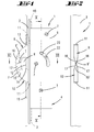
- Fig. 1
- eine Ansicht eines treibstangenbetätigbaren Hakenriegelverschlusses in seiner Verriegelungsstellung, wobei der Hakenriegelverschluss Zusatzschloss eines Treibstangenverschlusses ist,
- Fig. 2
- eine stulpseitige Ansicht des Hakenriegelverschlusses in der Verriegelungsstellung,
- Fig. 3
- eine Ansicht des Hakenriegelverschlusses in seiner Verriegelungsstellung bei abgenommener Schlossdecke,
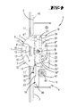
- Fig. 4
- eine Darstellung wie Fig. 3, wobei auch der unterhalb der Schlossdecke befindliche Treibstangen-Anschlussschieber fortgelassen ist,
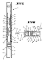
- Fig. 5
- den Schnitt nach der Linie V-V in Fig. 1,
- Fig. 6
- den Schnitt nach der Linie VI-VI in Fig. 1,
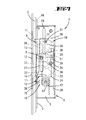
- Fig. 7
- eine der Fig. 3 vergleichbare Darstellung, jedoch die Offenstellung des Hakenriegelverschlusses betreffend,
- Fig. 8
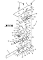
- in perspektivischer Darstellung die Schlossbauteile,
- Fig. 9
- eine ausschnittsweise Stulpansicht des Hakenriegelverschlusses bei abgewandelt gestalteten, in Überlapptstellung tretenden Hakenenden und
- Fig. 10
- eine Darstellung wie Fig. 9, wobei eine weitere Abwandlung der in Überlapptstellung tretenden Hakenenden vorgesehen ist.
Claims (11)
- Treibstangenbetätigbarer Hakenriegelverschluss (1) mit einem von einer Treibstange (3) um eine gehäusefeste Schwenkachse (8) schwenkbaren Hakenriegelorgan, welches in einer Offenstellung hinter einem Stulp (2) ins Schlossgehäuse (4) eingeschwenkt ist und in einer Verriegelungsstellung einen eine Schließeingriffsöffnung eines Gegenschließteiles (15) in zwei Teilöffnungen (13, 14) unterteilenden Steg (12) umfasst, dadurch gekennzeichnet, dass das Hakenriegelorgan von zwei insbesondere um eine gemeinsame Achse (8) gegenläufig schwenkbaren Einzelhakenriegeln (9, 10) gebildet ist, welche jeweils in eine der beiden Teilöffnungen (13, 14) eintreten.
- Hakenriegelverschluss nach Anspruch 1 oder insbesondere danach, dadurch gekennzeichnet, dass die Treibstangen-Anschlussschieber (18, 19) mittels eines Zahnrades (42) im Gegenlauf antreibbar sind.
- Hakenriegelverschluss nach einem oder mehreren der vorhergehenden Ansprüche oder insbesondere danach, dadurch gekennzeichnet, dass sich die Hakenenden (9', 10') der Einzelhakenriegel (9, 10) in der Verriegelungsstellung berühren oder nahezu berührend eine Überlapptstellung einnehmen.
- Hakenriegelverschluss nach einem oder mehreren der vorhergehenden Ansprüche oder insbesondere danach, gekennzeichnet durch eine Überlappung in der Verlagerungsebene und/ oder in der Stulpebene.
- Hakenriegelverschluss nach einem oder mehreren der vorhergehenden Ansprüche oder insbesondere danach, gekennzeichnet durch eine formschlüssige Überlappung.
- Hakenriegelverschluss nach einem oder mehreren der vorhergehenden Ansprüche oder insbesondere danach, dadurch gekennzeichnet, dass die Riegelschwänze (9", 10") der Einzelhakenriegel (9, 10) sich rückwärts der Schwenkachse (8) überlappen.
- Hakenriegelverschluss nach einem oder mehreren der vorhergehenden Ansprüche oder insbesondere danach, dadurch gekennzeichnet, dass die Riegelschwänze (9", 10") im rückwärtigen Überlappungsbereich stufenförmig abgesetzt sind derart, dass die Stufenflächen (9''', 10''') aufeinander abgleiten und sich die Stufen zur vollen Materialstärke des Hakenriegelorgans ergänzen, so dass die äußeren Breitseitenflächen (9"", 10"") der Riegelschwänze (9", 10") im Schlossgehäuse (4) insbesondere auf zwei gegenläufig angetriebenen Treibstangen-Anschlussschiebern (18, 19) geführt sind.
- Hakenriegelverschluss nach einem oder mehreren der vorhergehenden Ansprüche oder insbesondere danach, dadurch gekennzeichnet, dass die Stufenflächen (9''', 10''') von schlossbodenfesten oder schlossdeckenfesten Führungszapfen (30, 36) gestützt sind.
- Hakenriegelverschluss nach einem oder mehreren der vorhergehenden Ansprüche oder insbesondere danach, dadurch gekennzeichnet, dass die Führungszapfen (30, 36) Schlitze (28, 34) der Treibstangen-Anschlussschieber (18, 19) durchgreifen.
- Hakenriegelverschluss nach einem oder mehreren der vorhergehenden Ansprüche oder insbesondere danach, dadurch gekennzeichnet, dass jeder Einzelhakenriegel (9, 10) an seiner äußeren Seitenfläche (9"", 10"") einen Antriebszapfen (20, 21) trägt, der in einen Antriebsquerschlitz (24, 25) des ihm zugeordneten Treibstangen-Anschlussschiebers (18, 19) greift.
- Hakenriegelverschluss nach einem oder mehreren der vorhergehenden Ansprüche oder insbesondere danach, dadurch gekennzeichnet, dass der Antriebsschlitz (24, 25) endseitig eine Rückdrücksperrnische (24', 25') ausbildet.
Applications Claiming Priority (2)
| Application Number | Priority Date | Filing Date | Title |
|---|---|---|---|
| DE2002113344 DE10213344A1 (de) | 2002-03-26 | 2002-03-26 | Treibstangenbetätigbarer Hakenriegelverschluss |
| DE10213344 | 2002-03-26 |
Publications (2)
| Publication Number | Publication Date |
|---|---|
| EP1350914A2 true EP1350914A2 (de) | 2003-10-08 |
| EP1350914A3 EP1350914A3 (de) | 2006-04-19 |
Family
ID=27815933
Family Applications (1)
| Application Number | Title | Priority Date | Filing Date |
|---|---|---|---|
| EP03100766A Withdrawn EP1350914A3 (de) | 2002-03-26 | 2003-03-25 | Treibstangenbetätigbarer Hakenriegelverschluss |
Country Status (3)
| Country | Link |
|---|---|
| EP (1) | EP1350914A3 (de) |
| DE (1) | DE10213344A1 (de) |
| PL (1) | PL359356A1 (de) |
Cited By (13)
| Publication number | Priority date | Publication date | Assignee | Title |
|---|---|---|---|---|
| FR2928398A1 (fr) * | 2008-03-10 | 2009-09-11 | Ferco Int Usine Ferrures | Dispositif de verrouillage pour cremone ou cremone-serrure |
| CN102182365A (zh) * | 2011-05-03 | 2011-09-14 | 罗保德 | 防盗门锁 |
| RU2434111C2 (ru) * | 2007-07-09 | 2011-11-20 | Бьеркбода Лос Ой Аб | Улучшенный дверной замок с крючкообразным засовом |
| CN102661091A (zh) * | 2012-05-11 | 2012-09-12 | 章景林 | 具有副锁的防盗门锁 |
| DE102012011010A1 (de) * | 2012-06-02 | 2013-12-05 | Roto Frank Ag | Beschlagsystem für ein Fenster, eine Tür oder dergleichen |
| GB2508940A (en) * | 2012-12-17 | 2014-06-18 | Grouphomesafe Ltd | Locking unit having a pair of pivotal locking bolts |
| CN104948028A (zh) * | 2014-03-26 | 2015-09-30 | 奥尔本贾科莫-股份有限公司 | 防盗锁和锁叶 |
| CN104948027A (zh) * | 2014-03-26 | 2015-09-30 | 奥尔本贾科莫-股份有限公司 | 防盗锁 |
| CN105386658A (zh) * | 2015-12-18 | 2016-03-09 | 陈海敏 | 保险箱柜门扇的锁定装置 |
| CN107960716A (zh) * | 2017-12-04 | 2018-04-27 | 朱家珲 | 一种简易密码箱 |
| EP3470606A1 (de) * | 2017-10-11 | 2019-04-17 | Aug. Winkhaus GmbH & Co. KG | Verschluss für einen treibstangenbeschlag |
| US11692371B2 (en) * | 2017-04-06 | 2023-07-04 | Pella Corporation | Fenestration automation systems and methods |
| AU2018200563B2 (en) * | 2017-03-17 | 2023-12-21 | Illinois Tool Works Inc. | An improved lock for sliding doors |
Families Citing this family (2)
| Publication number | Priority date | Publication date | Assignee | Title |
|---|---|---|---|---|
| DE10352833A1 (de) * | 2003-11-12 | 2005-06-23 | Aug. Winkhaus Gmbh & Co. Kg | Treibstangenbeschlag |
| DE102019125148A1 (de) | 2019-09-18 | 2021-03-18 | WILKA Schließtechnik GmbH | Nebenschloss für eine Mehrpunktverriegelung |
Family Cites Families (5)
| Publication number | Priority date | Publication date | Assignee | Title |
|---|---|---|---|---|
| US1426805A (en) * | 1920-12-30 | 1922-08-22 | Arthur A Alexander | Lock |
| US1528515A (en) * | 1921-02-23 | 1925-03-03 | Edward M Cummings | Lock |
| DE19608173C2 (de) * | 1996-03-04 | 2002-03-14 | Wilka Schliestechnik Gmbh | Schloß, insbesondere Zusatzschloß |
| DE19813166A1 (de) * | 1998-03-25 | 1999-10-14 | Winkhaus Fa August | Türschloßanordnung, vorzugsweise Treibstangenschloßanordnung |
| FR2776697B1 (fr) * | 1998-03-30 | 2006-08-25 | Ojmar Sa | Serrure a double pene |
-
2002
- 2002-03-26 DE DE2002113344 patent/DE10213344A1/de not_active Withdrawn
-
2003
- 2003-03-25 EP EP03100766A patent/EP1350914A3/de not_active Withdrawn
- 2003-03-26 PL PL03359356A patent/PL359356A1/xx not_active Application Discontinuation
Cited By (23)
| Publication number | Priority date | Publication date | Assignee | Title |
|---|---|---|---|---|
| RU2434111C2 (ru) * | 2007-07-09 | 2011-11-20 | Бьеркбода Лос Ой Аб | Улучшенный дверной замок с крючкообразным засовом |
| FR2928398A1 (fr) * | 2008-03-10 | 2009-09-11 | Ferco Int Usine Ferrures | Dispositif de verrouillage pour cremone ou cremone-serrure |
| CN102182365B (zh) * | 2011-05-03 | 2016-05-04 | 罗保德 | 防盗门锁 |
| CN102182365A (zh) * | 2011-05-03 | 2011-09-14 | 罗保德 | 防盗门锁 |
| CN102661091B (zh) * | 2012-05-11 | 2015-01-21 | 章景林 | 具有副锁的防盗门锁 |
| CN102661091A (zh) * | 2012-05-11 | 2012-09-12 | 章景林 | 具有副锁的防盗门锁 |
| DE102012011010B4 (de) * | 2012-06-02 | 2014-12-04 | Roto Frank Ag | Beschlagsystem für ein Fenster, eine Tür oder dergleichen |
| DE102012011010A1 (de) * | 2012-06-02 | 2013-12-05 | Roto Frank Ag | Beschlagsystem für ein Fenster, eine Tür oder dergleichen |
| GB2508940A (en) * | 2012-12-17 | 2014-06-18 | Grouphomesafe Ltd | Locking unit having a pair of pivotal locking bolts |
| GB2508930A (en) * | 2012-12-17 | 2014-06-18 | Grouphomesafe Ltd | Locking unit having a pair of pivotal locking bolts |
| CN103867055A (zh) * | 2012-12-17 | 2014-06-18 | 家居安全组有限公司 | 与锁定装置相关的改进 |
| CN103867055B (zh) * | 2012-12-17 | 2019-03-12 | 时代家居安全有限公司 | 与锁定装置相关的改进 |
| GB2508930B (en) * | 2012-12-17 | 2018-07-18 | Era Home Security Ltd | Improvements relating to locking apparatus |
| CN104948028A (zh) * | 2014-03-26 | 2015-09-30 | 奥尔本贾科莫-股份有限公司 | 防盗锁和锁叶 |
| CN104948027B (zh) * | 2014-03-26 | 2019-01-25 | 奥尔本贾科莫-股份有限公司 | 防盗锁 |
| CN104948027A (zh) * | 2014-03-26 | 2015-09-30 | 奥尔本贾科莫-股份有限公司 | 防盗锁 |
| CN105386658B (zh) * | 2015-12-18 | 2017-09-29 | 陈海敏 | 保险箱柜门扇的锁定装置 |
| CN105386658A (zh) * | 2015-12-18 | 2016-03-09 | 陈海敏 | 保险箱柜门扇的锁定装置 |
| AU2018200563B2 (en) * | 2017-03-17 | 2023-12-21 | Illinois Tool Works Inc. | An improved lock for sliding doors |
| US11692371B2 (en) * | 2017-04-06 | 2023-07-04 | Pella Corporation | Fenestration automation systems and methods |
| US12473753B2 (en) | 2017-04-06 | 2025-11-18 | Pella Corporation | Fenestration automation systems and methods |
| EP3470606A1 (de) * | 2017-10-11 | 2019-04-17 | Aug. Winkhaus GmbH & Co. KG | Verschluss für einen treibstangenbeschlag |
| CN107960716A (zh) * | 2017-12-04 | 2018-04-27 | 朱家珲 | 一种简易密码箱 |
Also Published As
| Publication number | Publication date |
|---|---|
| EP1350914A3 (de) | 2006-04-19 |
| PL359356A1 (en) | 2003-10-06 |
| DE10213344A1 (de) | 2003-10-09 |
Similar Documents
| Publication | Publication Date | Title |
|---|---|---|
| EP1350914A2 (de) | Treibstangenbetätigbarer Hakenriegelverschluss | |
| EP0634552B1 (de) | Schloss mit Schwenkriegel, insbesondere als Zusatzschloss an Treibstangenschlössern | |
| EP0455944B1 (de) | Schliesszylinderbetätigbares Treibstangenschloss | |
| DE3520862A1 (de) | Treibstangenschloss | |
| EP0454966B1 (de) | Schliesszylinderbetätigbares Treibstangenschloss | |
| DE19727878A1 (de) | Querriegelschloß | |
| EP1020597A1 (de) | Treibstangenverschluss mit einem Hauptschloss und einem Nebenschloss | |
| EP0597170A1 (de) | Drehriegelverschluss | |
| EP0454959B1 (de) | Schliesszylinderbetätigbares Treibstangenschloss | |
| DE3427713C2 (de) | ||
| DE3148030A1 (de) | Zahnradantrieb in einem schliesszylinderbetaetigbaren treibstangenschloss mit schubriegel | |
| DE4015880C2 (de) | Treibstangenschloß | |
| EP0454960B1 (de) | Treibstangenschloss | |
| DE19815671B4 (de) | Treibstangenverschluß | |
| EP0454965B1 (de) | Einsteckschloss, insbesondere Treibstangenschloss | |
| EP1116841A1 (de) | Schloss, insbesondere Einsteckschloss | |
| EP0454958A1 (de) | Schloss, insbesondere Treibstangenschloss | |
| DE19608173C2 (de) | Schloß, insbesondere Zusatzschloß | |
| DE4302920C2 (de) | Schloß, insbesondere Einsteckschloß | |
| DE19841544A1 (de) | Zusatzschloß an einem Treibstangenverschluß | |
| DE3544257C2 (de) | ||
| DE4242523C2 (de) | Treibstangenschloß | |
| DE3807338A1 (de) | Schloss, insbesondere einsteckschloss | |
| DE2743091A1 (de) | Schloss | |
| DE7503160U (de) | Schloss, insbesondere einsteckschloss fuer rohrrahmentueren |
Legal Events
| Date | Code | Title | Description |
|---|---|---|---|
| PUAI | Public reference made under article 153(3) epc to a published international application that has entered the european phase |
Free format text: ORIGINAL CODE: 0009012 |
|
| AK | Designated contracting states |
Kind code of ref document: A2 Designated state(s): AT BE BG CH CY CZ DE DK EE ES FI FR GB GR HU IE IT LI LU MC NL PT RO SE SI SK TR |
|
| AX | Request for extension of the european patent |
Extension state: AL LT LV MK |
|
| PUAL | Search report despatched |
Free format text: ORIGINAL CODE: 0009013 |
|
| AK | Designated contracting states |
Kind code of ref document: A3 Designated state(s): AT BE BG CH CY CZ DE DK EE ES FI FR GB GR HU IE IT LI LU MC NL PT RO SE SI SK TR |
|
| AX | Request for extension of the european patent |
Extension state: AL LT LV MK |
|
| AKX | Designation fees paid | ||
| STAA | Information on the status of an ep patent application or granted ep patent |
Free format text: STATUS: THE APPLICATION IS DEEMED TO BE WITHDRAWN |
|
| 18D | Application deemed to be withdrawn |
Effective date: 20061020 |
|
| REG | Reference to a national code |
Ref country code: DE Ref legal event code: 8566 |