EP1350924A2 - Attachement des éléments de stator dans une turbine à gaz - Google Patents
Attachement des éléments de stator dans une turbine à gaz Download PDFInfo
- Publication number
- EP1350924A2 EP1350924A2 EP03003358A EP03003358A EP1350924A2 EP 1350924 A2 EP1350924 A2 EP 1350924A2 EP 03003358 A EP03003358 A EP 03003358A EP 03003358 A EP03003358 A EP 03003358A EP 1350924 A2 EP1350924 A2 EP 1350924A2
- Authority
- EP
- European Patent Office
- Prior art keywords
- stator blade
- blade segment
- housing
- gas turbine
- attachment according
- Prior art date
- Legal status (The legal status is an assumption and is not a legal conclusion. Google has not performed a legal analysis and makes no representation as to the accuracy of the status listed.)
- Granted
Links
Images


Classifications
-
- F—MECHANICAL ENGINEERING; LIGHTING; HEATING; WEAPONS; BLASTING
- F01—MACHINES OR ENGINES IN GENERAL; ENGINE PLANTS IN GENERAL; STEAM ENGINES
- F01D—NON-POSITIVE DISPLACEMENT MACHINES OR ENGINES, e.g. STEAM TURBINES
- F01D5/00—Blades; Blade-carrying members; Heating, heat-insulating, cooling or antivibration means on the blades or the members
- F01D5/12—Blades
- F01D5/22—Blade-to-blade connections, e.g. for damping vibrations
- F01D5/225—Blade-to-blade connections, e.g. for damping vibrations by shrouding
-
- F—MECHANICAL ENGINEERING; LIGHTING; HEATING; WEAPONS; BLASTING
- F01—MACHINES OR ENGINES IN GENERAL; ENGINE PLANTS IN GENERAL; STEAM ENGINES
- F01D—NON-POSITIVE DISPLACEMENT MACHINES OR ENGINES, e.g. STEAM TURBINES
- F01D25/00—Component parts, details, or accessories, not provided for in, or of interest apart from, other groups
- F01D25/24—Casings; Casing parts, e.g. diaphragms, casing fastenings
- F01D25/246—Fastening of diaphragms or stator-rings
-
- F—MECHANICAL ENGINEERING; LIGHTING; HEATING; WEAPONS; BLASTING
- F01—MACHINES OR ENGINES IN GENERAL; ENGINE PLANTS IN GENERAL; STEAM ENGINES
- F01D—NON-POSITIVE DISPLACEMENT MACHINES OR ENGINES, e.g. STEAM TURBINES
- F01D5/00—Blades; Blade-carrying members; Heating, heat-insulating, cooling or antivibration means on the blades or the members
- F01D5/12—Blades
- F01D5/26—Antivibration means not restricted to blade form or construction or to blade-to-blade connections or to the use of particular materials
-
- F—MECHANICAL ENGINEERING; LIGHTING; HEATING; WEAPONS; BLASTING
- F01—MACHINES OR ENGINES IN GENERAL; ENGINE PLANTS IN GENERAL; STEAM ENGINES
- F01D—NON-POSITIVE DISPLACEMENT MACHINES OR ENGINES, e.g. STEAM TURBINES
- F01D9/00—Stators
- F01D9/02—Nozzles; Nozzle boxes; Stator blades; Guide conduits, e.g. individual nozzles
- F01D9/04—Nozzles; Nozzle boxes; Stator blades; Guide conduits, e.g. individual nozzles forming ring or sector
- F01D9/041—Nozzles; Nozzle boxes; Stator blades; Guide conduits, e.g. individual nozzles forming ring or sector using blades
-
- F—MECHANICAL ENGINEERING; LIGHTING; HEATING; WEAPONS; BLASTING
- F05—INDEXING SCHEMES RELATING TO ENGINES OR PUMPS IN VARIOUS SUBCLASSES OF CLASSES F01-F04
- F05B—INDEXING SCHEME RELATING TO WIND, SPRING, WEIGHT, INERTIA OR LIKE MOTORS, TO MACHINES OR ENGINES FOR LIQUIDS COVERED BY SUBCLASSES F03B, F03D AND F03G
- F05B2260/00—Function
- F05B2260/30—Retaining components in desired mutual position
- F05B2260/301—Retaining bolts or nuts
-
- F—MECHANICAL ENGINEERING; LIGHTING; HEATING; WEAPONS; BLASTING
- F05—INDEXING SCHEMES RELATING TO ENGINES OR PUMPS IN VARIOUS SUBCLASSES OF CLASSES F01-F04
- F05D—INDEXING SCHEME FOR ASPECTS RELATING TO NON-POSITIVE-DISPLACEMENT MACHINES OR ENGINES, GAS-TURBINES OR JET-PROPULSION PLANTS
- F05D2230/00—Manufacture
- F05D2230/60—Assembly methods
- F05D2230/64—Assembly methods using positioning or alignment devices for aligning or centring, e.g. pins
Definitions
- the invention relates to a stator blade segment attachment for a gas turbine with a housing on which several stator blade segments are stored.
- Stator blades of gas turbines are usually considered segment-like Components designed to be used in a housing or attached to a housing. Constructions of the named Art shows, for example, US 6,296,443 B1.
- stator blade segments vane spans
- they assign, for example, as in the above US document mentions feet or grooves on that are correspondingly positively connected to the housing.
- the invention has for its object a stator blade segment attachment to create for a gas turbine which at simple structure and inexpensive to manufacture Avoids disadvantages of the prior art and one reliable fastening of the stator blade segments allows.
- the object is achieved by the combination of features of the main claim solved, the sub-claims show more advantageous embodiments of the invention.
- stator blade segment fastening according to the invention is distinguished is characterized by a number of significant advantages.
- the principle underlying the invention is that Bracing the stator blade segments against the housing. This are slightly deformed. In the same way can also subjected the housing to a corresponding deformation become. Through this deliberately caused elastic deformation tolerances or play of the fasteners are eliminated. Unwanted vibrations or the like are thus completely prevented or at least strongly suppressed. Farther can be achieved by the configuration according to the invention that the respective free ends of the stator blade segments fit tightly against the housing and therefore not itself detach from the housing.
- the means for bracing the stator blade segment include preferably an actuating element, which has a favorable design of the invention in the form of a screw can be.
- This screw can, for example, in a threaded recess of the housing. It is then, for example designed as a lag screw. Alternatively it is also possible to use pressure screws or others Provide preloading means.
- the radius of the housing in the area of the stator blade segments is smaller than the radius of the respective Stator vane. This ensures that the free end areas of the stator blade segments against the housing fit and can be tensioned accordingly.
- FIG. 1 shows a perspective view of a stator blade segment, such as this from the prior art per se is already known.
- This includes several stator blades that are attached to a circular segment-shaped outer support 6 and optionally a circular segment-shaped inner support 7 are attached.
- the outer carrier 6 and the inner carrier 7 can with lateral Feet or approaches or provided with appropriate grooves be the attachment in a housing 1 (see Fig. 3) or on an inside cover tape. These configurations are known from the prior art, so that on can be referred to this.
- a rotation of the stator blade segments 2 in the housing can by so-called vane stops be prevented.
- the stator blade segment shown in FIG. 1 has for example, a groove 8.
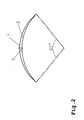
- FIG. 2 shows the schematic mode of operation in a side view the invention before tightening.
- a housing 1 With the outside Circular arc is shown a housing 1, while the inner Circular arc reproduces a stator blade segment 2.
- the reference number 3 refers to pretensioners.
- Fig. 2 is a tension of the stator blade segment 2 to form a space in the middle Area so that the free ends of the stator blade segment bear against the housing 1 or be pressed against it.
- Fig. 3 shows a simplified side view in the unstressed Condition in which it can be seen that the prestressing means 3 are in the form of a screw 4 which in a thread recess of the not shown in detail Housing 1 is guided.
- the screw is, for example, as Traction screw designed to the stator blade segment 2 in the described way to deform.
Landscapes
- Engineering & Computer Science (AREA)
- Mechanical Engineering (AREA)
- General Engineering & Computer Science (AREA)
- Turbine Rotor Nozzle Sealing (AREA)
- Structures Of Non-Positive Displacement Pumps (AREA)
Applications Claiming Priority (2)
| Application Number | Priority Date | Filing Date | Title |
|---|---|---|---|
| DE10214569A DE10214569A1 (de) | 2002-04-02 | 2002-04-02 | Statorschaufelsegmentbefestigung für eine Gasturbine |
| DE10214569 | 2002-04-02 |
Publications (3)
| Publication Number | Publication Date |
|---|---|
| EP1350924A2 true EP1350924A2 (fr) | 2003-10-08 |
| EP1350924A3 EP1350924A3 (fr) | 2005-02-02 |
| EP1350924B1 EP1350924B1 (fr) | 2007-01-24 |
Family
ID=27816105
Family Applications (1)
| Application Number | Title | Priority Date | Filing Date |
|---|---|---|---|
| EP03003358A Expired - Lifetime EP1350924B1 (fr) | 2002-04-02 | 2003-02-14 | Attachement des éléments de stator dans une turbine à gaz |
Country Status (3)
| Country | Link |
|---|---|
| US (1) | US6863497B2 (fr) |
| EP (1) | EP1350924B1 (fr) |
| DE (2) | DE10214569A1 (fr) |
Cited By (2)
| Publication number | Priority date | Publication date | Assignee | Title |
|---|---|---|---|---|
| CN103154524A (zh) * | 2010-08-11 | 2013-06-12 | 航空技术空间股份有限公司 | 轴向涡轮机压缩器的外壳 |
| CN103154524B (zh) * | 2010-08-11 | 2016-11-30 | 赛峰航空助推器股份有限公司 | 轴向涡轮机压缩器的外壳 |
Families Citing this family (7)
| Publication number | Priority date | Publication date | Assignee | Title |
|---|---|---|---|---|
| US20080221710A1 (en) * | 2006-10-13 | 2008-09-11 | General Electric Company | System and methods for reducing an effect of a disturbance |
| US7421354B2 (en) * | 2006-10-13 | 2008-09-02 | General Electric Company | Systems and methods for reducing an effect of a disturbance |
| EP2573328A1 (fr) * | 2011-09-20 | 2013-03-27 | Siemens Aktiengesellschaft | Anneau de stator pour turbomachine et procédé de fonctionnement de l'anneau de stator |
| US10428832B2 (en) | 2012-08-06 | 2019-10-01 | United Technologies Corporation | Stator anti-rotation lug |
| US20160017731A1 (en) * | 2014-07-17 | 2016-01-21 | Rolls-Royce Corporation | Vane assembly |
| EP2977548B1 (fr) * | 2014-07-22 | 2021-03-10 | Safran Aero Boosters SA | Aube et turbomachine associée |
| US11125092B2 (en) | 2018-08-14 | 2021-09-21 | Raytheon Technologies Corporation | Gas turbine engine having cantilevered stators |
Family Cites Families (8)
| Publication number | Priority date | Publication date | Assignee | Title |
|---|---|---|---|---|
| DE826673C (de) * | 1945-04-04 | 1952-01-03 | Maschf Augsburg Nuernberg Ag | Leitapparat mit keramischen Leitschaufeln |
| US2857093A (en) * | 1954-12-02 | 1958-10-21 | Cincinnati Testing & Res Lab | Stator casing and blade assembly |
| GB856599A (en) * | 1958-06-16 | 1960-12-21 | Gen Motors Corp | Improvements relating to axial-flow compressors |
| DE2152365C3 (de) * | 1971-02-03 | 1973-12-06 | Carrier Corp., Syracuse, N.Y. (V.St.A.) | Einrichtung zum Lagern der inneren Enden von drehbar gelagerten Leitschaufeln einer Axial Stromungs maschine |
| DE2165529A1 (de) * | 1971-12-30 | 1973-07-05 | Kloeckner Humboldt Deutz Ag | Einrichtung zum zentrieren und fixieren eines koerpers |
| DE2643285C3 (de) * | 1976-09-25 | 1979-03-08 | Motoren- Und Turbinen-Union Muenchen Gmbh, 8000 Muenchen | Abstützvorrichtung für eine ein in Umfangsrichtung wirkendes Drehmoment aufnehmende Komponente in einem Stapel von Komponenten eines Gasturbinentriebwerkes, insbesondere eines Leitschaufelkranzes, im Gehäuse |
| US5846050A (en) * | 1997-07-14 | 1998-12-08 | General Electric Company | Vane sector spring |
| US6296443B1 (en) | 1999-12-03 | 2001-10-02 | General Electric Company | Vane sector seating spring and method of retaining same |
-
2002
- 2002-04-02 DE DE10214569A patent/DE10214569A1/de not_active Withdrawn
-
2003
- 2003-02-14 EP EP03003358A patent/EP1350924B1/fr not_active Expired - Lifetime
- 2003-02-14 DE DE50306344T patent/DE50306344D1/de not_active Expired - Lifetime
- 2003-04-01 US US10/403,054 patent/US6863497B2/en not_active Expired - Fee Related
Cited By (2)
| Publication number | Priority date | Publication date | Assignee | Title |
|---|---|---|---|---|
| CN103154524A (zh) * | 2010-08-11 | 2013-06-12 | 航空技术空间股份有限公司 | 轴向涡轮机压缩器的外壳 |
| CN103154524B (zh) * | 2010-08-11 | 2016-11-30 | 赛峰航空助推器股份有限公司 | 轴向涡轮机压缩器的外壳 |
Also Published As
| Publication number | Publication date |
|---|---|
| US6863497B2 (en) | 2005-03-08 |
| US20030185683A1 (en) | 2003-10-02 |
| DE50306344D1 (de) | 2007-03-15 |
| EP1350924B1 (fr) | 2007-01-24 |
| EP1350924A3 (fr) | 2005-02-02 |
| DE10214569A1 (de) | 2003-10-16 |
Similar Documents
| Publication | Publication Date | Title |
|---|---|---|
| EP0906514B1 (fr) | Rotor pour une turbomachine avec des pales a monter dans des rainures et pales pour un rotor | |
| DE102008014678B4 (de) | Turbolader mit einer variablen Turbinengeometrie VTG | |
| EP3017146B1 (fr) | Rotor pour dispositif turbocompresseur, dispositif turbocompresseur équipé d'un rotor et arbre pour un tel rotor | |
| EP1092081A1 (fr) | Rotor pour turbomachine | |
| EP1881236B1 (fr) | Entraînement par vis à billes | |
| EP3990804B1 (fr) | Engrenage planétaire sans jeu | |
| EP1348077B1 (fr) | Compresseur frigorifique | |
| EP3717801B1 (fr) | Mécanisme d'entraînement à vis sans fin | |
| EP1350924A2 (fr) | Attachement des éléments de stator dans une turbine à gaz | |
| EP1584793A2 (fr) | Dispositif pour la fixation d'aubes de turbine | |
| DE102005052951B4 (de) | Verfahren und Werkzeug zur Montage/Demontage von Bremsscheiben | |
| DE60220476T2 (de) | Anordnung einer Ausgangswelle für das Steuersystem einer Rakete | |
| DE1162465B (de) | Zu einem selbsttragenden Bauelement verspanntes Laeuferblechpaket fuer elektrische Maschinen | |
| EP1707759B1 (fr) | Carter d'une turbomachine | |
| EP3336319A1 (fr) | Dispositif de réglage destiné au réglage d'aubes directrices multiples d'un groupe propulseur | |
| EP1728972A2 (fr) | Dispositif de verrouillage d'une aube de turbine | |
| EP3765769A1 (fr) | Engrenage à roues dentées | |
| DE102012017979B4 (de) | Spindelantrieb | |
| DE102016207698A1 (de) | Ladeeinrichtung | |
| EP1055051A1 (fr) | Systeme de liaison de deux disques de turbine d'une turbomachine axiale | |
| DE10392948B4 (de) | Drehbarer Antrieb und Schaltmechanismus mit diesem drehbaren Antrieb | |
| WO2006117140A2 (fr) | Dispositif d'assemblage entre un galet de roulement et un dispositif de serrage | |
| DE10316004A1 (de) | Lager für eine Windenergieanlage | |
| DE19544981A1 (de) | Spannring zur Befestigung von Bremsscheiben, insbesondere Wellenbremsscheiben von Schienenfahrzeugen | |
| DE102018202276B4 (de) | Flüssigkeitspumpe mit Vibrationsdämpfungselement |
Legal Events
| Date | Code | Title | Description |
|---|---|---|---|
| PUAI | Public reference made under article 153(3) epc to a published international application that has entered the european phase |
Free format text: ORIGINAL CODE: 0009012 |
|
| AK | Designated contracting states |
Kind code of ref document: A2 Designated state(s): AT BE BG CH CY CZ DE DK EE ES FI FR GB GR HU IE IT LI LU MC NL PT SE SI SK TR |
|
| AX | Request for extension of the european patent |
Extension state: AL LT LV MK RO |
|
| PUAL | Search report despatched |
Free format text: ORIGINAL CODE: 0009013 |
|
| AK | Designated contracting states |
Kind code of ref document: A3 Designated state(s): AT BE BG CH CY CZ DE DK EE ES FI FR GB GR HU IE IT LI LU MC NL PT SE SI SK TR |
|
| AX | Request for extension of the european patent |
Extension state: AL LT LV MK RO |
|
| 17P | Request for examination filed |
Effective date: 20050519 |
|
| AKX | Designation fees paid |
Designated state(s): DE FR GB |
|
| GRAP | Despatch of communication of intention to grant a patent |
Free format text: ORIGINAL CODE: EPIDOSNIGR1 |
|
| GRAS | Grant fee paid |
Free format text: ORIGINAL CODE: EPIDOSNIGR3 |
|
| GRAA | (expected) grant |
Free format text: ORIGINAL CODE: 0009210 |
|
| AK | Designated contracting states |
Kind code of ref document: B1 Designated state(s): DE FR GB |
|
| REG | Reference to a national code |
Ref country code: GB Ref legal event code: FG4D Free format text: NOT ENGLISH |
|
| GBT | Gb: translation of ep patent filed (gb section 77(6)(a)/1977) |
Effective date: 20070124 |
|
| REF | Corresponds to: |
Ref document number: 50306344 Country of ref document: DE Date of ref document: 20070315 Kind code of ref document: P |
|
| ET | Fr: translation filed | ||
| PLBE | No opposition filed within time limit |
Free format text: ORIGINAL CODE: 0009261 |
|
| STAA | Information on the status of an ep patent application or granted ep patent |
Free format text: STATUS: NO OPPOSITION FILED WITHIN TIME LIMIT |
|
| 26N | No opposition filed |
Effective date: 20071025 |
|
| REG | Reference to a national code |
Ref country code: DE Ref legal event code: R082 Ref document number: 50306344 Country of ref document: DE Representative=s name: WABLAT LANGE KARTHAUS ANWALTSSOZIETAET, DE |
|
| REG | Reference to a national code |
Ref country code: DE Ref legal event code: R082 Ref document number: 50306344 Country of ref document: DE Representative=s name: WABLAT LANGE KARTHAUS ANWALTSSOZIETAET, DE Effective date: 20130402 Ref country code: DE Ref legal event code: R081 Ref document number: 50306344 Country of ref document: DE Owner name: ROLLS-ROYCE DEUTSCHLAND LTD & CO KG, DE Free format text: FORMER OWNER: ROLLS-ROYCE DEUTSCHLAND LTD & CO KG, 15827 BLANKENFELDE, DE Effective date: 20130402 |
|
| PGFP | Annual fee paid to national office [announced via postgrant information from national office to epo] |
Ref country code: FR Payment date: 20140317 Year of fee payment: 12 |
|
| PGFP | Annual fee paid to national office [announced via postgrant information from national office to epo] |
Ref country code: GB Payment date: 20140227 Year of fee payment: 12 |
|
| PGFP | Annual fee paid to national office [announced via postgrant information from national office to epo] |
Ref country code: DE Payment date: 20140327 Year of fee payment: 12 |
|
| REG | Reference to a national code |
Ref country code: DE Ref legal event code: R119 Ref document number: 50306344 Country of ref document: DE |
|
| GBPC | Gb: european patent ceased through non-payment of renewal fee |
Effective date: 20150214 |
|
| REG | Reference to a national code |
Ref country code: FR Ref legal event code: ST Effective date: 20151030 |
|
| PG25 | Lapsed in a contracting state [announced via postgrant information from national office to epo] |
Ref country code: GB Free format text: LAPSE BECAUSE OF NON-PAYMENT OF DUE FEES Effective date: 20150214 Ref country code: DE Free format text: LAPSE BECAUSE OF NON-PAYMENT OF DUE FEES Effective date: 20150901 |
|
| PG25 | Lapsed in a contracting state [announced via postgrant information from national office to epo] |
Ref country code: FR Free format text: LAPSE BECAUSE OF NON-PAYMENT OF DUE FEES Effective date: 20150302 |