EP1350942A2 - Dispositif et méthode de gestion du mauvais fonctionnement d'un inverseur de poussée - Google Patents
Dispositif et méthode de gestion du mauvais fonctionnement d'un inverseur de poussée Download PDFInfo
- Publication number
- EP1350942A2 EP1350942A2 EP03075993A EP03075993A EP1350942A2 EP 1350942 A2 EP1350942 A2 EP 1350942A2 EP 03075993 A EP03075993 A EP 03075993A EP 03075993 A EP03075993 A EP 03075993A EP 1350942 A2 EP1350942 A2 EP 1350942A2
- Authority
- EP
- European Patent Office
- Prior art keywords
- engine
- processing subsystem
- eec
- relay switch
- thrust control
- Prior art date
- Legal status (The legal status is an assumption and is not a legal conclusion. Google has not performed a legal analysis and makes no representation as to the accuracy of the status listed.)
- Granted
Links
- 230000007257 malfunction Effects 0.000 title claims abstract description 66
- 238000000034 method Methods 0.000 title claims description 13
- 238000012545 processing Methods 0.000 claims abstract description 119
- 230000004308 accommodation Effects 0.000 claims abstract description 9
- 239000000446 fuel Substances 0.000 claims description 42
- 238000012544 monitoring process Methods 0.000 claims description 9
- 230000002159 abnormal effect Effects 0.000 description 19
- 230000007423 decrease Effects 0.000 description 3
- 230000000694 effects Effects 0.000 description 2
- 231100001261 hazardous Toxicity 0.000 description 2
- 238000012360 testing method Methods 0.000 description 2
- 230000001133 acceleration Effects 0.000 description 1
- 238000013459 approach Methods 0.000 description 1
- 230000003247 decreasing effect Effects 0.000 description 1
- 238000013461 design Methods 0.000 description 1
- 208000037218 exstrophy-epispadias complex Diseases 0.000 description 1
- ZZUFCTLCJUWOSV-UHFFFAOYSA-N furosemide Chemical compound C1=C(Cl)C(S(=O)(=O)N)=CC(C(O)=O)=C1NCC1=CC=CO1 ZZUFCTLCJUWOSV-UHFFFAOYSA-N 0.000 description 1
- 238000012986 modification Methods 0.000 description 1
- 230000004048 modification Effects 0.000 description 1
- 230000001960 triggered effect Effects 0.000 description 1
Images


Classifications
-
- F—MECHANICAL ENGINEERING; LIGHTING; HEATING; WEAPONS; BLASTING
- F01—MACHINES OR ENGINES IN GENERAL; ENGINE PLANTS IN GENERAL; STEAM ENGINES
- F01D—NON-POSITIVE DISPLACEMENT MACHINES OR ENGINES, e.g. STEAM TURBINES
- F01D21/00—Shutting-down of machines or engines, e.g. in emergency; Regulating, controlling, or safety means not otherwise provided for
-
- F—MECHANICAL ENGINEERING; LIGHTING; HEATING; WEAPONS; BLASTING
- F01—MACHINES OR ENGINES IN GENERAL; ENGINE PLANTS IN GENERAL; STEAM ENGINES
- F01D—NON-POSITIVE DISPLACEMENT MACHINES OR ENGINES, e.g. STEAM TURBINES
- F01D21/00—Shutting-down of machines or engines, e.g. in emergency; Regulating, controlling, or safety means not otherwise provided for
- F01D21/14—Shutting-down of machines or engines, e.g. in emergency; Regulating, controlling, or safety means not otherwise provided for responsive to other specific conditions
-
- F—MECHANICAL ENGINEERING; LIGHTING; HEATING; WEAPONS; BLASTING
- F02—COMBUSTION ENGINES; HOT-GAS OR COMBUSTION-PRODUCT ENGINE PLANTS
- F02C—GAS-TURBINE PLANTS; AIR INTAKES FOR JET-PROPULSION PLANTS; CONTROLLING FUEL SUPPLY IN AIR-BREATHING JET-PROPULSION PLANTS
- F02C9/00—Controlling gas-turbine plants; Controlling fuel supply in air- breathing jet-propulsion plants
-
- F—MECHANICAL ENGINEERING; LIGHTING; HEATING; WEAPONS; BLASTING
- F02—COMBUSTION ENGINES; HOT-GAS OR COMBUSTION-PRODUCT ENGINE PLANTS
- F02C—GAS-TURBINE PLANTS; AIR INTAKES FOR JET-PROPULSION PLANTS; CONTROLLING FUEL SUPPLY IN AIR-BREATHING JET-PROPULSION PLANTS
- F02C9/00—Controlling gas-turbine plants; Controlling fuel supply in air- breathing jet-propulsion plants
- F02C9/26—Control of fuel supply
- F02C9/46—Emergency fuel control
Definitions
- the invention relates generally to thrust controls for aircraft engines, and more specifically to a thrust control system to promptly correct a thrust control malfunction, thereby ensuring that no single fault of an aircraft's propulsion control system will result in an unaccommodated thrust control malfunction.
- a particularly hazardous situation is when a thrust control system failure results in one of the aircraft's engines continuing to operate at a high power condition and not responding to a throttle command to reduce power during takeoff, approach or landing.
- the actual thrust either increases to a significantly higher than commanded thrust and/or remains at a high level when the thrust levers are set for low thrust.
- a high asymmetric thrust condition occurs, creating a high lateral force on the aircraft that is very difficult for a pilot to control. Even if the asymmetry can be controlled, the excess thrust may cause the airplane's stopping distance to exceed the available runway length. In such cases, exceptional skills and prompt flight crew action may not be adequate to avoid risks to aircraft safety.
- Some recent thrust limiting systems have reduced the potential for this failure mode to occur, but have not eliminated the risk.
- Known limiting systems include automatic engine shutdown and thrust cutback features, but are designed to be activated only if the engine rotor speed exceeds specified levels. These levels will not necessarily be exceeded in the event of a thrust control malfunction.
- Increased traffic and congestion, as well as the increased use of parallel taxiways and runways have increased the potential for an aircraft experiencing such a failure to impact other aircraft, ground support equipment, or a terminal. Thus, such a failure could potentially impact the occupants of multiple aircraft, terminal spaces, and/or ground support personnel.
- an automatic thrust control malfunction accommodation system that would automatically detect a failure of an aircraft engine to throttle down when idle or low thrust is selected, and mitigate the failure by automatically reducing engine power. Such a system would ensure that no single fault of an aircraft's propulsion control system will result in an unaccommodated thrust control malfunction. It would also be desirable to implement such a system in existing aircraft design by exploiting the resources of the existing engine control system without adding any major new components.
- the present invention is directed to a system and method for detecting and correcting a thrust control malfunction in an aircraft engine.
- the system includes an electronic engine control (EEC) unit that includes a first processing subsystem and a second processing subsystem, and a thrust control malfunction accommodation (TCMA) circuit included in the first processing subsystem and the second processing subsystem.
- EEC electronic engine control
- TCMA thrust control malfunction accommodation
- the system includes a TCMA software package executed by the first processing subsystem and the second processing subsystem, thereby providing redundant execution of the TCMA software package.
- the method of the present invention compares the engine's actual power level with a threshold contour defined by the TCMA software package.
- the TCMA software package determines that a thrust control malfunction has occurred, based on the engine's power level exceeding the threshold contour, the engine is shut down by the TCMA circuit.
- the present invention is still further directed to an electronic engine control (EEC) unit configured to detect and correct an aircraft engine thrust control malfunction using an active-active functionality.
- EEC electronic engine control
- the EEC includes a first processing subsystem for unilaterally monitoring engine operation and shutting down the engine when a thrust control malfunction occurs, and a second processing subsystem for unilaterally monitoring engine operation and shutting down the engine when a thrust control malfunction occurs.
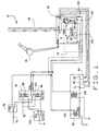
- FIG. 1 is a schematic of an aircraft engine control system 10, in accordance with a preferred embodiment of the present invention, including a thrust control malfunction accommodation (TCMA) circuit 16.
- TCMA circuit 16 is included in an electronic engine control (EEC) 18 that is mounted on an aircraft engine.
- EEC 18 includes a first processing subsystem 20a, or channel A, and a second processing subsystem 20b, or channel B.
- TCMA circuit 16 includes a first EEC channel relay switch 22, a second EEC channel relay switch 28 and a diode 32.
- the adjectives "first" and “second”, as used herein are not intended to imply an order of importance or a sequence, but merely used to arbitrarily identify two similar objects or components.
- System 10 includes the EEC 18, a thrust lever 36, digital Aeronautical Radio Incorporated (ARINC) data bus lines 46, an electrical load management system (ELMS) 52, a high pressure shutoff valve (HPSOV) 58, and a hydro mechanical unit (HMU) 64.
- Thrust lever 36 is electrically connected to EEC processing subsystems 20a and 20b.
- ARINC data bus lines 46 are electrically connected to EEC 18.
- ELMS 52 is electrically connected to TCMA circuit 16 within EEC 18 and HPSOV 58.
- HMU 64 is electrically connected between HPSOV 58 and EEC 18.
- HMU 64 includes a first fuel metering valve (FMV) torque motor 66, a second FMV torque motor 68, and a feedback device 70.
- First torque motor 66 is controlled by EEC first processing subsystem 20a and second torque motor 68 is controlled by EEC second processing subsystem 20b.
- FMV fuel metering valve
- system 10 includes a first voltage input 72 and a second voltage input 76 that supply predetermined voltages to system 10, for example 28 volts DC.
- First input 72 is electrically connected to a fire relay switch 82 and second input 76 is electrically connected to a run coil 88 and a cutoff coil 96, both included in ELMS 52.
- a HPSOV closed coil 100 is connected to fire relay switch 82, an ELMS relay switch 102 and diode 32.
- system 10 includes a fuel control relay switch 108 that is electrically connected to run coil 88 and cutoff coil 96. When in the run position, ELMS relay switch 102 is electrically connected to EEC relay switch 22. When in the cutoff position, ELMS relay switch 102 is connected to HPSOV closed relay switch 100 and diode 32.
- a HPSOV open coil 118 is electrically connected to EEC 18 at an output 124.
- HPSOV 58 is controlled by fuel control relay switch 108, which is located in the cockpit of the aircraft. Placing fuel control switch 108 in the run position while fire relay switch 82 is in the normal position causes input 72 to supply voltage, for example 28 volts DC, across HPSOV open coil 118.
- voltage is supplied across ELMS run coil 88, which energizes ELMS run coil 88 and causes ELMS relay switch 102 to be in the run position.
- ELMS relay switch 102 With ELMS relay switch 102 in the run position, ELMS 52 supplies electrical current to EEC first channel relay switch 22.
- switch 22 If switch 22 is in the run position, current flows to EEC second channel relay switch 28, and if switch 28 is also in the run position, voltage is applied across HPSOV open coil 118, which energizes HPSOV open coil 118 and allows fuel to flow to the engine utilizing HMU 64. Thus, for HPSOV open coil 118 to be energized, and for fuel to flow to the engine, both EEC first channel relay switch 22 and EEC second channel relay switch 28 must be in the run position. If either one of the EEC channel switches 22 and 28 is in the cutoff position HPSOV open coil 118 is not energized and HPSOV closed coil 100 is energized, thereby closing the HPSOV and shutting off fuel flow to the engine.
- Placing fuel control switch 108 in the cutoff position causes input 72 to supply voltage, for example, 28 volts DC, across HPSOV closed coil 100.
- voltage is supplied across ELMS cutoff coil 96.
- This energizes ELMS cutoff coil 96 and causes ELMS relay switch 102 to be in the cutoff position.
- Current flows to HPSOV closed coil 100, thereby energizing HPSOV closed coil 100.
- Energizing HPSOV closed coil 100 shuts off fuel flow to the engine utilizing HMU 64.
- EEC diode 32 prevents current from flowing from ELMS relay switch 102 to EEC channel switches 22 and 28, thereby protecting against a short to ground inside EEC 18. This ensures that failures inside EEC 18 do not prevent a pilot from being able to shut off the fuel to the engine using fuel control switch 108.
- EEC first processing subsystem 20a i.e. channel A
- EEC second processing subsystem 20b i.e. channel B
- the processing subsystem will close its respective relay switch 22 or 28.
- fuel control switch 108 is in the run position, and either EEC relay switches 22 or 28 are moved to the cutoff position, the current flowing to HPSOV open coil 118 is diverted to HPSOV closed coil 100.
- HPSOV open coil 118 is de-energized and HPSOV closed coil 100 is energized, thereby shutting off fuel flow to the engine and causing the engine to shut down.
- TCMA circuit 16 is controlled by first processing subsystem 20a and second processing subsystem 20b.
- the first processing subsystem 20a and the second processing subsystem 20b redundantly execute the engine control malfunction software package 130 to determine when an engine shutdown should be triggered.
- each of the processing subsystems 20a and 20b monitors the position of thrust lever 36, engine power level, and several other digital inputs provided from the aircraft via digital ARINC data buses 46.
- Typical EECs installed on modern commercial transport airplanes include two processing subsystem, or channels, arranged in an active/hot-spare configuration such that one processing subsystem is actively controlling the engine while the other processing subsystem is just operating as a ready spare, with its outputs de-powered. Failure of one processing subsystem does not preclude dispatch, as long as the remaining processing subsystem can provide full functionality. Typically the aircraft is allowed to operate for a limited period of time with just a single operative processing subsystem.
- EEC 18 utilizes an active/active configuration.
- EEC first processing subsystem 20a and EEC second processing subsystem 20b are both always actively monitoring engine function and independently have the capability of shutting down the engine. However, with respect to all the other engine control functions, one of processing subsystems 20a or 20b is in active control and the other processing subsystem is in standby mode.
- TCMA circuit 16 provides the ability for either EEC first processing subsystem 20a or EEC second processing subsystem 20b to unilaterally shut off fuel flow to the engine by removing voltage from HPSOV open coil 118 and applying voltage to HPSOV closed coil 100. Therefore, the active/active configuration allows for failure of the relay in the processing subsystem that is actively controlling, i.e.
- first channel relay 22 or second channel relay 28 because the standby processing subsystem still performs the TCMA function.
- implementation of TCMA circuit 16 only requires minimal changes in airplane wiring from the baseline system.
- Engine control system 10 implements engine malfunction control software package 130 which is stored in the dedicated memory device of processing subsystem 20a and the dedicated memory device of processing subsystem 20b. Execution of the software package 130 stored in each processing subsystem monitors the functioning of the same engine, thereby providing redundant engine monitoring systems.
- the processor in processing subsystem 20a executes the malfunction software package 130 stored in the memory device of processing subsystem 20a
- the processor in processing subsystem 20b executes the malfunction software package 130 stored in the memory device of processing subsystem 20b.
- Each software package 130 is executed independent of the other, thereby providing redundant protection against such a malfunction.
- thrust control malfunction circuit 16 is a redundant circuit that utilizes both processing subsystems 20a and 20b to unilaterally execute software package 130 included in each respective processing subsystem. Therefore, the description of the function, use, and execution of engine control malfunction software package 130 herein refers to the simultaneous function, use and execution of the software package 130 included in processing subsystem 20a and the software package 130 included in processing subsystem 20b.
- Software package 130 determines whether there is an engine malfunction of the type occurring when a pilot has commanded the engine to idle speed, via throttle 36 input, but the engine does not decelerate normally. If such an engine malfunction occurs when the aircraft is on the ground, software package 130 automatically cuts fuel to the engine causing the engine to shut down.
- Software package 130 utilizes processing subsystems 20a and 20b to determine when throttle 36 is set to idle and whether an engine thrust control malfunction has occurred.
- Processing subsystems 20a and 20b of EEC 18 each receive signals from a throttle resolver (not shown) that indicates the setting, or position, of throttle 36.
- the throttle position defines the thrust level commanded by the pilot or an autothrottle system, and EEC 18 determines a power set command, and then modulates the fuel to achieve that command, whether the command is rotor speed or engine pressure ratio.
- processing subsystem 20a and processing subsystem 20b each receive a signal indicating engine power level indicated by actual rotor speed or actual engine pressure ratio.
- These throttle position signals, engine power level commands, and engine power level signals are monitored by software package 130.
- software package 130 develops, or derives, a contour threshold from the power lever 36 command and the expected engine response, which is used to determine when an engine malfunction occurs. The contour threshold is described further below in reference to Figure 2.
- Software package 130 monitors engine power level and compares the power level to the threshold contour. If, when the aircraft is on the ground, throttle 36 is set to idle speed and the engine power level exceeds the threshold contour, software package 130 of one or both processing subsystems 20a and 20b will shut down the engine by cutting fuel to the engine. Software package 130 cuts fuel to the engine by causing EEC 18 to remove voltage across HPSOV open coil 118 and introducing voltage across HPSOV closed coil 100.
- engine power level is based on engine fan speed.
- engine power level can be determined in any feasible manner, for example, the engine power level can be based on an engine pressure ratio (EPR), or EPR analytically converted to fan speed, or compressor speed.
- EPR engine pressure ratio
- software package 130 is executed while the aircraft is in flight and on the ground, software package will only cut fuel to the engine if the aircraft is on the ground.
- Software package 130 monitors the flight status of the aircraft using system information received by EEC 18.
- Figure 2 is a graphical representation 200 showing the execution of software package 130 (shown in Figure 1) during four scenarios of normal engine operation.
- Graphical representation 200 includes a first normal operation scenario 206, a second normal operation scenario 212, a third normal operation scenario 218, and a fourth normal operation scenario 224.
- Each of scenarios 206, 212, 218, and 224 shows a threshold contour 230 derived by software package 130, an actual engine power curve 236 and a commanded power curve 242.
- Commanded power 242 is based on the positioning, or maneuvering, of throttle 36 (shown in Figure 1).
- First normal operation scenario 206 depicts how software package 130 functions when throttle 36 is maneuvered such that engine power is increased from an idle power level to a desired level and decreased back to the idle power level.
- Commanded power 242 starts at an idle command (IC) level and increases to a desired power command (DPC) level as throttle 36 is advanced.
- IC idle command
- DPC desired power command
- software package 130 sets threshold contour 230 at an idle threshold (IT) level, which is a predetermined engine power level ( ⁇ EPL) above the idle command level IC.
- Threshold contour 230 will never go below the idle threshold level IT.
- threshold contour 230 tracks commanded power 242, increasing at the same rate until commanded power 242 plateaus at the desired power command level DPC.
- software package 130 increases threshold contour 230 to a desired power threshold level (DPT), which is a predetermined power level ( ⁇ DPL) above the desired power commanded level DPC.
- DPT desired power threshold level
- ⁇ DPL predetermined power level
- first normal operation scenario 206 shows actual engine power 236 increasing, or spooling up, until actual engine power 236 reaches the desired power commanded level DPC.
- the engine may overshoot the desired power commanded level DPC slightly.
- Contour 230 accounts for the overshoot by setting ⁇ DPL large enough to allow for the engine power overshoot without actual engine power 236 reaching the desired power threshold DPT.
- first normal operation scenario 206 shows how when throttle 36 is retarded, or pulled back, commanded power 242 is reduced from the desired power command level DPC to the idle command level IC.
- software package 130 When commanded power 242 is lowered to the idle command level IC, software package 130 no longer derives threshold contour 230 based on commanded power 242. Instead, software package 130 derives threshold contour 230 based on a function of a normal engine power deceleration rate.
- the normal engine power deceleration rate is mapped using engine characteristics, test data and predictive mathematical analysis.
- the function reduces the power level of threshold contour 236 from desired power threshold level DPT to idle threshold level IT at a rate equal to the normal engine deceleration rate plus a predetermined amount of margin ⁇ SDP.
- Second normal operation scenario 212 depicts how software package 130 functions when throttle 36 is maneuvered such that engine power is increased from an idle power level to a desired level, then increased again to another desired level, and then spooled down to yet another desired level and finally spooled back down to the idle power level.
- commanded power 242 starts at the idle command level IC
- threshold contour 230 starts at the idle threshold level IT.
- commanded power 242 is increased to a first desired power command level (DPC 1 ) and threshold contour 230 tracks commanded power 242 until commanded power 242 plateaus.
- software package 130 sets threshold contour 230 at a first desired power threshold level (DPT 1 ) that is the predetermined power level ⁇ DPL above desired power command level DPC 1 .
- Commanded power 242 is then increased to a second desired power command level (DPC 2 ).
- threshold contour 230 tracks commanded power 242 and gets set at a second desired power threshold level (DPT 2 ) that is the predetermined power level ⁇ DPL above DPC 2 .
- Throttle 36 is then retarded and commanded power 242 steps down to a third desired power command level (DPC 3 ).
- software package 130 determines threshold command 230 based on a function of normal engine deceleration.
- software package 130 reduces threshold contour 230 at a rate equal to the normal engine deceleration rate plus the predetermined amount of margin ⁇ SDP.
- threshold contour 230 As commanded power 242 plus ⁇ DPL, software package 130 again derives threshold contour 230 as commanded power 242 plus ⁇ DPL. Throttle 36 is then retarded again causing commanded power 242 to decline to idle power level IC and actual power 236 to spool down to idle power level IC at a certain rate. Once again, as actual power 236 spools down, software 130 derives threshold contour 230 as a function of the normal engine deceleration rate until threshold contour 230 reaches the idle threshold level IT, at which point threshold contour 230 levels off at the idle threshold level IT.
- Third normal operation scenario 218 depicts how software package 130 functions when throttle 36 is positioned such that engine power is increased from an idle power level to a desired level, but the engine does not spool up to the desired level.
- commanded power 242 starts at the idle command level IC
- threshold contour 230 starts at the idle threshold level IT.
- Throttle 36 is advanced and commanded power 242 is increased to the desired power command level DPC and threshold contour 230 tracks commanded power 242 until commanded power 242 plateaus.
- software package 130 sets threshold contour at the desired power threshold level DPT that is the predetermined power level ⁇ DPL above the desired power command level DPC.
- actual power 236 does not spool up to the desired power command level DPC, but only reaches an insufficient power level (IPL).
- Throttle 36 is then pulled back to idle because the engine is not spooling up to the desired power commanded level DPC.
- software 130 determines whether actual power 236 has reached the desired power command level DPC. If actual power 236 is at the desired power command level DPC, then software package 130 derives the threshold contour based on a function of the normal engine deceleration rate, as described above in reference to first normal operation scenario 206. If actual power 236 is not at the desired power command level DPC, software package 130 identifies the insufficient power level IPL, and sets threshold contour equal to the insufficient power level IPL plus a predetermined amount of power ⁇ IPL. From the insufficient power level IPL plus ⁇ IPL point to the idle command level IC, software package 130 derives threshold contour 230 based on the function of the normal engine deceleration rate.
- Fourth normal operation scenario 224 depicts how software package 130 functions when throttle 36 is positioned such that engine power is increased from idle power to a desired power, but then retarded to idle as the engine is spooling up.
- commanded power 242 starts at the idle command level IC and threshold contour 230 starts at the idle threshold level IT.
- Throttle 36 is advanced and commanded power 242 is increased to the desired power command level DPC.
- Threshold contour 230 tracks commanded power 242 until commanded power 242 plateaus.
- software package 130 sets threshold contour at the desired power threshold level DPT, which is the predetermined power level ⁇ DPL above the desired power command level DPC.
- commanded power 242 is pulled back to the idle command power level IC while actual power 236 is still spooling up and has only reached the insufficient power level IPC.
- threshold contour 130 takes into account the fact that the engine cannot instantaneously begin to decelerate, but must first turn around.
- software 130 determines whether actual power 236 has reached the desired power command level DPC. If actual power 236 has reached the desired power command level DPC, software package 130 derives threshold contour 230 based on a function the normal engine deceleration rate, as described above in reference to first scenario 206. If actual power 236 has not reached the desired power command level DPC, software package 130 determines the insufficient power level IPL.
- Software package 130 then sets threshold contour 230 equal to the insufficient power level IPL plus the predetermined amount of power ⁇ IPL determined form the acceleration rate at the time the throttle was retarded to idle. From the insufficient power level IPL plus ⁇ IPL point to the idle command level IC, software package 130 derives threshold contour 230 based on the function of the normal engine deceleration rate.
- Figure 3 is a graphical representation 300 showing the execution of software package 130 (shown in Figure 1) during four scenarios of abnormal engine operation. Components shown in Figure 3 that are identical to components shown in Figure 2 are identified in Figure 3 using numerals incremented by 100 over the numerals used in Figure 2.
- Graphical representation 300 includes a first abnormal operation scenario 306, a second abnormal operation scenario 312, a third abnormal operation scenario 318, and a fourth abnormal operation scenario 324.
- Each of scenarios 306, 312, 318, and 324 shows a threshold contour 330 developed, or derived, by software package 130, an actual engine power curve 336 and a commanded power curve 342.
- Commanded power 342 is based on the positioning, or maneuvering, of throttle 36 (shown in Figure 1).
- First abnormal operation scenario 306 depicts how software package 130 functions when throttle 36 is advanced, then pulled back to idle because the engine continues to accelerate after reaching a desired power level.
- first normal operation scenario 206 shown in Figure 2
- commanded power 342 increases from the idle command level IC to the desired power command level DPC
- threshold contour 330 increases from the idle threshold level IT to the desired power threshold level DPT.
- Scenario 306 shows actual engine power 336 spooling up and reaching the desired power command level DPC, but then continuing to spool up and exceeding the desired power threshold level DPT.
- Throttle 36 is then retarded, or pulled back, causing commanded power 342 to fall to the idle command level IC and threshold contour 330 to decline to the idle threshold level IT at a rate based on the function of the normal engine power deceleration rate.
- the normal engine power deceleration rate is mapped using engine characteristics, test data and predictive mathematical analysis.
- the related software package 130 cuts fuel by closing the related relay switch 22 or 28 of thrust control malfunction accommodation circuit 16. If software package 130 in first processing subsystem 20a, i.e. channel A, identifies the thrust control malfunction, relay switch 22 is moved to the cutoff position. Likewise, if software package 130 in second processing subsystem 20b, i.e. channel B, identifies the thrust control malfunction, relay switch 28 is moved to the cutoff position. Upon moving either relay switch 22 or relay switch 28 to the cutoff position, voltage is removed from HPSOV open coil 118 and applied across HPSOV closed coil 100, thereby cutting fuel to the engine and causing the engine to shut down. Software package 130 only identifies a thrust control malfunction and cuts fuel to the engine when software package 130 verifies that the aircraft is on the ground, throttle 36 has been pulled back to the idle position, and actual engine power 336 exceeds threshold contour 330.
- Second abnormal operation scenario 312 depicts how software package 130 functions when the engine has achieved a desired power level but does not spool down normally when throttle 36 is pulled back to the idle position.
- Scenario 312 shows that throttle 36 has been advanced causing commanded power 342 to increase from the idle command level IC to the desired power command level DPC and threshold contour 330 to increase from the idle threshold level IT to the desired power threshold level DPT.
- Actual engine power 336 spools up to a point past the desired power command level DPC, but does not exceed the desired power threshold level DPT. Then throttle 36 is pulled back to the idle position causing commanded power 342 to step down to the idle command level IC.
- threshold contour 330 decreases to the idle threshold level IT at a rate based on a function of the normal engine deceleration rate, as described above in reference to first normal operation scenario 206 (shown in Figure 2).
- abnormal operation scenario 312 actual engine power 336 does not spool down at the normal engine deceleration rate and therefore exceeds threshold contour 330.
- software package 130 identifies the abnormal engine performance as a thrust control malfunction and cuts fuel to the engine. As described above in reference to first abnormal operation scenario 306, based on which processing subsystem, or channel, of EEC 18 identifies the thrust control malfunction, the related software package 130 cuts fuel by closing the related relay switch 22 or 28 of thrust control malfunction accommodation circuit 16.
- Third abnormal operation scenario 318 depicts how software package 130 functions when throttle 36 is advanced, but the engine does not spool up to the desired level, and throttle 36 is pulled back to the idle position.
- Scenario 318 shows that throttle 36 has been advanced causing commanded power 342 to increase from the idle command level IC to the desired power command level DPC and threshold contour 330 to increase from the idle threshold level IT to the desired power threshold level DPT.
- actual engine power 336 spools up but only to an insufficient power level (IPL).
- Throttle 36 is then pulled back to idle because the engine is not spooling up to the desired power commanded level DPC.
- software 130 determines whether actual engine power 336 has reached the desired power command level DPC. If actual power 336 has reached the desired power command level DPC, software package 130 derives threshold contour 330 based on a function of the normal engine deceleration rate. If actual power 236 has not reached the DPC, software package 130 identifies the insufficient power level IPL, and sets threshold contour 330 equal to the insufficient power level IPL plus the predetermined amount of power ⁇ IPL. From the insufficient power level IPL plus ⁇ IPL point to the idle command level IC, software package 130 derives threshold contour 330 based on the function of the normal engine deceleration rate.
- abnormal operation scenario 318 the engines fails to spool down when throttle 36 is pulled back to idle. Therefore, actual engine power 336 remains at the insufficient power level IPL and exceeds threshold contour 330.
- software package 130 identifies the abnormal engine performance as a thrust control malfunction and cuts fuel to the engine as described above in reference to first abnormal operation scenario 306.
- Fourth abnormal operation scenario 324 depicts how software package 130 functions when throttle 36 is in an idle position and the engine runs away.
- Scenario 324 shows commanded power 342 remaining at the idle command level IC, threshold contour 330 remaining at the idle threshold level IT, and actual engine power 336 spooling up and exceeding threshold contour 330.
- software package 130 identifies the abnormal engine performance as a thrust control malfunction and cuts fuel to the engine as described above in reference to first abnormal operation scenario 306.
Landscapes
- Engineering & Computer Science (AREA)
- Mechanical Engineering (AREA)
- General Engineering & Computer Science (AREA)
- Chemical & Material Sciences (AREA)
- Combustion & Propulsion (AREA)
- Combined Controls Of Internal Combustion Engines (AREA)
- Safety Devices In Control Systems (AREA)
- Hardware Redundancy (AREA)
- Control Of Vehicle Engines Or Engines For Specific Uses (AREA)
Applications Claiming Priority (2)
| Application Number | Priority Date | Filing Date | Title |
|---|---|---|---|
| US116655 | 1987-11-04 | ||
| US10/116,655 US6704630B2 (en) | 2002-04-04 | 2002-04-04 | Thrust control malfunction accommodation system and method |
Publications (3)
| Publication Number | Publication Date |
|---|---|
| EP1350942A2 true EP1350942A2 (fr) | 2003-10-08 |
| EP1350942A3 EP1350942A3 (fr) | 2004-09-29 |
| EP1350942B1 EP1350942B1 (fr) | 2010-06-23 |
Family
ID=28041089
Family Applications (1)
| Application Number | Title | Priority Date | Filing Date |
|---|---|---|---|
| EP03075993A Expired - Lifetime EP1350942B1 (fr) | 2002-04-04 | 2003-04-03 | Dispositif et méthode de gestion du mauvais fonctionnement d'un contrôleur de poussée |
Country Status (5)
| Country | Link |
|---|---|
| US (1) | US6704630B2 (fr) |
| EP (1) | EP1350942B1 (fr) |
| BR (1) | BR0301658A (fr) |
| CA (1) | CA2424251C (fr) |
| DE (1) | DE60333056D1 (fr) |
Cited By (1)
| Publication number | Priority date | Publication date | Assignee | Title |
|---|---|---|---|---|
| WO2016009155A1 (fr) * | 2014-07-18 | 2016-01-21 | Snecma | Procédé de commande d'une vanne d'arrêt bistable pour moteur d'aéronef |
Families Citing this family (19)
| Publication number | Priority date | Publication date | Assignee | Title |
|---|---|---|---|---|
| US20040088085A1 (en) * | 2002-10-30 | 2004-05-06 | Pratt & Whitney Canada Corp. | Method and system for preventing un-commanded power surge of aircraft engine |
| GB0307032D0 (en) * | 2003-03-26 | 2003-04-30 | Rolls Royce Plc | A control system |
| FR2870000B1 (fr) * | 2004-05-05 | 2006-08-11 | Hispano Suiza Sa | Controle de la robustesse d'une modelisation d'un systeme physique |
| US7711455B1 (en) * | 2006-08-09 | 2010-05-04 | The United States Of America As Represented By The Administrator Of The National Aeronautics And Space Administration | Propulsion controlled aircraft computer |
| DE102008009652A1 (de) * | 2008-02-18 | 2009-08-27 | Robert Bosch Gmbh | Überwachungseinrichtung und Überwachungsverfahren für einen Sensor, sowie Sensor |
| US9043050B2 (en) * | 2008-08-13 | 2015-05-26 | The Boeing Company | Programmable reverse thrust detent system and method |
| FR2956380B1 (fr) | 2010-02-15 | 2012-07-13 | Snecma | Procede et dispositif de protection contre des anomalies de commande de poussee de moteur d'avion |
| GB201301791D0 (en) | 2013-02-01 | 2013-03-20 | Rolls Royce Engine Control Systems Ltd | Engine fuel control system |
| US10487752B2 (en) * | 2015-03-11 | 2019-11-26 | Pratt & Whitney Canada Corp. | Overthrust protection system and method |
| US11686212B2 (en) | 2016-05-24 | 2023-06-27 | General Electric Company | Turbine engine and method of cooling |
| US10040564B2 (en) * | 2016-11-02 | 2018-08-07 | General Electric Company | Managing an input device |
| US10443512B2 (en) | 2017-03-31 | 2019-10-15 | Pratt & Whitney Canada Corp. | Detection of uncommanded and uncontrollable high thrust events |
| US10302021B2 (en) | 2017-05-03 | 2019-05-28 | Pratt & Whitney Canada Corp. | Detection of uncommanded and uncontrollable high thrust events |
| US10823113B2 (en) | 2017-08-21 | 2020-11-03 | Pratt & Whitney Canada Corp. | Method and system for limiting power of an engine |
| US10823041B2 (en) | 2017-12-19 | 2020-11-03 | Pratt & Whitney Canada Corp. | Engine assembly with plenum and remote fan |
| US11111814B2 (en) | 2017-12-20 | 2021-09-07 | General Electric Company | Turbine engine operational testing |
| US20210215104A1 (en) * | 2020-01-15 | 2021-07-15 | Pratt & Whitney Canada Corp. | Method and system for controlling operation of an engine using an engine controller |
| CN115979671B (zh) * | 2023-01-05 | 2025-09-23 | 上海瓶钵信息科技有限公司 | 基于时间限制的车辆下线检测方法、系统介质及设备 |
| CN119860297B (zh) * | 2023-10-20 | 2025-11-14 | 中国航发商用航空发动机有限责任公司 | 燃油调节器及燃油调节方法 |
Family Cites Families (5)
| Publication number | Priority date | Publication date | Assignee | Title |
|---|---|---|---|---|
| US4136517A (en) * | 1976-07-06 | 1979-01-30 | General Electric Company | Thrust control system for a gas turbine engine |
| US4313167A (en) * | 1979-07-27 | 1982-01-26 | General Electric Company | Thrust control system for a gas turbine engine |
| US5111402A (en) * | 1990-01-19 | 1992-05-05 | Boeing Company | Integrated aircraft test system |
| US6085127A (en) * | 1997-03-18 | 2000-07-04 | Aurora Flight Sciences Corporation | Fault tolerant automatic control system utilizing analytic redundancy |
| JP2001107751A (ja) * | 1999-10-05 | 2001-04-17 | Honda Motor Co Ltd | 航空機用ガスタービン・エンジンの制御装置 |
-
2002
- 2002-04-04 US US10/116,655 patent/US6704630B2/en not_active Expired - Lifetime
-
2003
- 2003-03-31 CA CA002424251A patent/CA2424251C/fr not_active Expired - Lifetime
- 2003-04-03 EP EP03075993A patent/EP1350942B1/fr not_active Expired - Lifetime
- 2003-04-03 DE DE60333056T patent/DE60333056D1/de not_active Expired - Lifetime
- 2003-04-04 BR BR0301658-7A patent/BR0301658A/pt not_active Application Discontinuation
Cited By (4)
| Publication number | Priority date | Publication date | Assignee | Title |
|---|---|---|---|---|
| WO2016009155A1 (fr) * | 2014-07-18 | 2016-01-21 | Snecma | Procédé de commande d'une vanne d'arrêt bistable pour moteur d'aéronef |
| FR3023871A1 (fr) * | 2014-07-18 | 2016-01-22 | Snecma | Procede de commande d'un actionneur bistable pour moteur d'aeronef |
| US10018073B2 (en) | 2014-07-18 | 2018-07-10 | Safran Aircraft Engines | Method for controlling a bistable shutoff valve for an aircraft engine |
| RU2681403C2 (ru) * | 2014-07-18 | 2019-03-06 | Сафран Эркрафт Энджинз | Способ управления бистабильным вентилем выключения для авиационного двигателя |
Also Published As
| Publication number | Publication date |
|---|---|
| DE60333056D1 (de) | 2010-08-05 |
| EP1350942A3 (fr) | 2004-09-29 |
| US20030191565A1 (en) | 2003-10-09 |
| EP1350942B1 (fr) | 2010-06-23 |
| CA2424251A1 (fr) | 2003-10-04 |
| BR0301658A (pt) | 2004-08-24 |
| CA2424251C (fr) | 2007-10-23 |
| US6704630B2 (en) | 2004-03-09 |
Similar Documents
| Publication | Publication Date | Title |
|---|---|---|
| US6704630B2 (en) | Thrust control malfunction accommodation system and method | |
| EP3909857B1 (fr) | Systèmes de commande pour centrales électriques hybrides | |
| CA2856547C (fr) | Systemes de commande automatique de blocs d'alimentation auxiliaire d'un aeronef, et procedes associes | |
| US9359961B2 (en) | Method of controlling an overspeed safety system for aeroengines and a control circuit for implementing said method | |
| CN108603444B (zh) | 部分冗余的电子控制系统 | |
| US8224552B2 (en) | Methods and systems to facilitate over-speed protection | |
| EP3101277B1 (fr) | Aéronef avec ventilateur de refroidissement de frein | |
| CN103930347B (zh) | 用于在至少一个航空器引擎故障的情况下调节功率的方法和系统 | |
| CA2923405C (fr) | Mecanisme et methode de protection contre le charriage | |
| US9944400B2 (en) | Adaptive engine acceleration for accessory loads | |
| CA2665799A1 (fr) | Methodes et systemes facilitant la protection contre les survitesses | |
| US9790807B2 (en) | Turbomachine comprising a monitoring system comprising a module for engaging a protection function of the turbomachine and monitoring method | |
| US12523181B2 (en) | Device for blocking the shut-off of a propulsion engine for aircraft | |
| US20100005657A1 (en) | Methods and systems to facilitate over-speed protection | |
| CN113650792A (zh) | 控制发动机关闭的控制系统和包括该控制系统的飞行器 | |
| US7856295B2 (en) | Device for issuing authorization to act on the operating conditions of an aircraft engine and engine control system comprising same | |
| US9914547B2 (en) | Aircraft equipped with a device for monitoring the electronic management of the engines | |
| EP1032811B1 (fr) | Procédé adaptatif de vitesse pour le testage de commande | |
| EP3219965B1 (fr) | Système de gestion de puissance au décollage et procédé pour moteurs de turbine à gaz | |
| US20260043362A1 (en) | Automated control of turbine engines of a rotary-wing aircraft during a failure on a turbine engine | |
| BLEEG | Commercial jet transport fly-by-wire architecture considerations | |
| CN112429245B (zh) | 飞行器环控系统管路超压保护系统和方法 | |
| CN118953695A (zh) | 一种确定舰载机航空发动机故障处置策略的辅助系统 | |
| GB2461609A (en) | Method and system to facilitate over-speed protection |
Legal Events
| Date | Code | Title | Description |
|---|---|---|---|
| PUAI | Public reference made under article 153(3) epc to a published international application that has entered the european phase |
Free format text: ORIGINAL CODE: 0009012 |
|
| AK | Designated contracting states |
Kind code of ref document: A2 Designated state(s): AT BE BG CH CY CZ DE DK EE ES FI FR GB GR HU IE IT LI LU MC NL PT RO SE SI SK TR |
|
| AX | Request for extension of the european patent |
Extension state: AL LT LV MK |
|
| PUAL | Search report despatched |
Free format text: ORIGINAL CODE: 0009013 |
|
| AK | Designated contracting states |
Kind code of ref document: A3 Designated state(s): AT BE BG CH CY CZ DE DK EE ES FI FR GB GR HU IE IT LI LU MC NL PT RO SE SI SK TR |
|
| AX | Request for extension of the european patent |
Extension state: AL LT LV MK |
|
| RIC1 | Information provided on ipc code assigned before grant |
Ipc: 7F 02C 9/46 B Ipc: 7F 01D 21/14 A |
|
| 17P | Request for examination filed |
Effective date: 20050329 |
|
| AKX | Designation fees paid |
Designated state(s): DE FR |
|
| 17Q | First examination report despatched |
Effective date: 20051027 |
|
| RAP1 | Party data changed (applicant data changed or rights of an application transferred) |
Owner name: THE BOEING COMPANY |
|
| GRAP | Despatch of communication of intention to grant a patent |
Free format text: ORIGINAL CODE: EPIDOSNIGR1 |
|
| RTI1 | Title (correction) |
Free format text: THRUST CONTROL MALFUNCTION ACCOMMODATION SYSTEM AND METHOD |
|
| GRAS | Grant fee paid |
Free format text: ORIGINAL CODE: EPIDOSNIGR3 |
|
| GRAA | (expected) grant |
Free format text: ORIGINAL CODE: 0009210 |
|
| AK | Designated contracting states |
Kind code of ref document: B1 Designated state(s): DE FR |
|
| REF | Corresponds to: |
Ref document number: 60333056 Country of ref document: DE Date of ref document: 20100805 Kind code of ref document: P |
|
| PLBE | No opposition filed within time limit |
Free format text: ORIGINAL CODE: 0009261 |
|
| STAA | Information on the status of an ep patent application or granted ep patent |
Free format text: STATUS: NO OPPOSITION FILED WITHIN TIME LIMIT |
|
| 26N | No opposition filed |
Effective date: 20110324 |
|
| REG | Reference to a national code |
Ref country code: DE Ref legal event code: R097 Ref document number: 60333056 Country of ref document: DE Effective date: 20110323 |
|
| REG | Reference to a national code |
Ref country code: FR Ref legal event code: PLFP Year of fee payment: 14 |
|
| REG | Reference to a national code |
Ref country code: FR Ref legal event code: PLFP Year of fee payment: 15 |
|
| REG | Reference to a national code |
Ref country code: FR Ref legal event code: PLFP Year of fee payment: 16 |
|
| PGFP | Annual fee paid to national office [announced via postgrant information from national office to epo] |
Ref country code: FR Payment date: 20220425 Year of fee payment: 20 Ref country code: DE Payment date: 20220427 Year of fee payment: 20 |
|
| REG | Reference to a national code |
Ref country code: DE Ref legal event code: R071 Ref document number: 60333056 Country of ref document: DE |
|
| P01 | Opt-out of the competence of the unified patent court (upc) registered |
Effective date: 20230503 |