EP1350969A1 - Befestigungsanordnung - Google Patents
Befestigungsanordnung Download PDFInfo
- Publication number
- EP1350969A1 EP1350969A1 EP03006267A EP03006267A EP1350969A1 EP 1350969 A1 EP1350969 A1 EP 1350969A1 EP 03006267 A EP03006267 A EP 03006267A EP 03006267 A EP03006267 A EP 03006267A EP 1350969 A1 EP1350969 A1 EP 1350969A1
- Authority
- EP
- European Patent Office
- Prior art keywords
- contour
- jumps
- component
- arrangement according
- pressure surface
- Prior art date
- Legal status (The legal status is an assumption and is not a legal conclusion. Google has not performed a legal analysis and makes no representation as to the accuracy of the status listed.)
- Granted
Links
Images



Classifications
-
- F—MECHANICAL ENGINEERING; LIGHTING; HEATING; WEAPONS; BLASTING
- F16—ENGINEERING ELEMENTS AND UNITS; GENERAL MEASURES FOR PRODUCING AND MAINTAINING EFFECTIVE FUNCTIONING OF MACHINES OR INSTALLATIONS; THERMAL INSULATION IN GENERAL
- F16B—DEVICES FOR FASTENING OR SECURING CONSTRUCTIONAL ELEMENTS OR MACHINE PARTS TOGETHER, e.g. NAILS, BOLTS, CIRCLIPS, CLAMPS, CLIPS OR WEDGES; JOINTS OR JOINTING
- F16B35/00—Screw-bolts; Stay-bolts; Screw-threaded studs; Screws; Set screws
- F16B35/04—Screw-bolts; Stay-bolts; Screw-threaded studs; Screws; Set screws with specially-shaped head or shaft in order to fix the bolt on or in an object
- F16B35/041—Specially-shaped shafts
- F16B35/048—Specially-shaped necks
-
- F—MECHANICAL ENGINEERING; LIGHTING; HEATING; WEAPONS; BLASTING
- F16—ENGINEERING ELEMENTS AND UNITS; GENERAL MEASURES FOR PRODUCING AND MAINTAINING EFFECTIVE FUNCTIONING OF MACHINES OR INSTALLATIONS; THERMAL INSULATION IN GENERAL
- F16B—DEVICES FOR FASTENING OR SECURING CONSTRUCTIONAL ELEMENTS OR MACHINE PARTS TOGETHER, e.g. NAILS, BOLTS, CIRCLIPS, CLAMPS, CLIPS OR WEDGES; JOINTS OR JOINTING
- F16B39/00—Locking of screws, bolts or nuts
- F16B39/22—Locking of screws, bolts or nuts in which the locking takes place during screwing down or tightening
- F16B39/28—Locking of screws, bolts or nuts in which the locking takes place during screwing down or tightening by special members on, or shape of, the nut or bolt
- F16B39/282—Locking by means of special shape of work-engaging surfaces, e.g. notched or toothed nuts
Definitions
- the present invention relates to a fastening arrangement, comprising on the one hand a fastener that has a force applied to a lathe and with a conical or dome-shaped curved pressure surface, in the Area several distributed over their circumference and their actual surface curvature interrupting contour jumps (recesses or projections) are formed and, on the other hand, comprise a component which can be connected to the fastening means, that a conical or dome-like curved contact surface for the pressure surface of the Fastener has.
- the invention further relates to the two Components of the fastening arrangement mentioned as individual parts.
- the pressure surface of the fastener is used - according to Art a countersunk screw - for engaging in a countersunk or in some areas accordingly conical or dome-like recessed mounting hole of the to be fastened Component.
- wheel bolts for fastening Wheels or rims on a motor vehicle.
- the fastener consists of a threaded shaft and the one end on Threaded shaft arranged head, the latter at the transition to the threaded shaft which has a conical or dome-shaped curved pressure surface.
- the problem mentioned is to be solved by the fact that in the area of Pressure surface of the fastening means arranged several distributed over the circumference and contour recesses interrupting the curvature of the pressure surface are formed are. By the remaining surface of the pressure surface by these contour recesses is reduced, when tightening the fastener with the same Torque reaches an increased surface pressure, which is also reflected in an increase of the loosening torque. This is caused by the contour recesses a slight deformation occurs in the area of the pressure surface, namely especially in each case in the border area to the contour recesses.
- the fastener known arrangement provided in the area of the peripheral surface or in the area of Contour jumps at least one elevation, preferably several elevations, to arrange.
- the amount of the survey can be chosen in particular that the survey at the beginning, in a middle section, and / or at the end of an insertion process an elastic and / or plastic deformation of the elevation itself and / or the part with which the screwing takes place.
- the invention has for its object a mounting arrangement of the beginning mentioned type (as a whole and in its two individual main components) constructively simple and economical way of increasing the To improve loosening torque.
- this is achieved in that in the area of the contact surface several distributed over their circumference and their actual surface curvature interrupting counter-contour jumps (projections or recesses) are formed in the connected state of the fastener and component form-fitting in the contour jumps (recesses or projections) of the pressure surface intervene, the pressure surface with the contour jumps and the contact surface with the counter contour jumps are dimensioned such that when connecting Fasteners and components no permanent shape changes occur.
- this can improve the friction behavior be provided for the invention that in the area of the pressure surface or in the area of contour recesses - as from the German utility model DE 299 14 357 U1 known - elevations - or depressions - are arranged, wherein but again in the area of the contact surface or in the area of the contour projections complementary wells - or surveys - are arranged so that the Elevations in the connected state of the fastener and component form-fitting engage in the depressions, and being the elevations and depressions are dimensioned such that when connecting fasteners and component no permanent changes in shape occur.
- a maximum respective dimension (depth or height) of the contour jumps in relation to the contact surface and a maximum respective counter dimension (height or depth) of the counter contour jumps in relation to the contact surface as well as the respective height of any elevations and the respective depth of any existing depressions can advantageously be taken into account, at least in this case the respective crushing limits R dF obtained from the compression test according to DIN 50 106 of the materials of the fastening means and the component, but preferably taking into account the respective 0.2% compression limit R d0.2 .
- a fastener according to the invention such as a wheel bolt or Intermediate disc, is thus assigned a mounting arrangement, on the one hand the fastener comprises a head with a force application for a Turning tool and with a conical or dome-shaped curved pressure surface, in the area of which several distributed over their circumference and their actual surface interruption interrupting contour jumps (contour recesses or contour projections) are formed, and the other one with the Fastening means connectable component which has a conical or dome-like curved Has contact surface for the pressure surface of the fastener, wherein in the area of the contact surface, several distributed over their circumference and theirs actual surface curvature interrupting counter contour jumps (Contour protrusions or contour recesses) are formed, which are intended in the connected state of the fastener and component in a positive manner in the contour jumps to engage the pressure surface, the pressure surface with the Contour jumps and the contact surface with the opposite contour jumps are dimensioned in this way are that when connecting fasteners and component no permanent Shape changes
- a component according to the invention such as a wheel rim or washer, is thus assigned to a fastening arrangement which on the one hand comprises a fastening means, the one head with a force application for a turning tool and with a conical or has dome-like curved pressure surface, in the area of which several over their Circumferentially distributed and interrupting their actual surface curvature Contour jumps (contour recesses or contour projections) are formed, and the component which can be connected to the fastening means comprises one conical or dome-like curved contact surface for the pressure surface of the fastener has, in the area of the contact surface several over their Circumferentially distributed and interrupting their actual surface curvature Counter-contour jumps (contour projections or contour recesses) are formed that are intended in the connected state of the fastener and component intervene positively in the contour jumps of the pressure surface, the Contact surface with the contour jumps and the contact surface with the counter contour jumps are dimensioned such that when connecting fasteners
- FIG. 7 and 9 for the second Execution
- Fig. 13 and 15 for the third embodiment
- the head 4 has a force application 6 for a turning tool on.
- the force application 6 is in each case designed as an external hexagon, but any other design is also possible, for example a hexagon socket or the like.
- the head 4 has a tapering in the direction of the threaded shaft 2 Pressure surface 8 on.
- this pressure surface 8 is conical or conical.
- a dome-like curved pressure surface 8 At the third and fourth embodiment (Fig. 13 to 18, Fig. 19 to 24) is a dome-like curved pressure surface 8.
- the pressure surface 8 engages in a corresponding recessed, e.g. B. recessed portion of a mounting hole 102 one for the first four versions of the fastening arrangement according to the invention in each case in FIGS. 4 to 6, 10 to 12, 16 to 18 and 22 to 24 shown, to be fastened or with the fastener 1 to be connected component 101.
- the component 101 has one conical (first and second version) or dome-shaped (third and fourth Execution) contact surface 108 for the pressure surface 8 of the fastener 1.
- the flats 10 run in strips with im substantially constant width and substantially rectilinear in the direction of Longitudinal axis of the threaded shaft 2 across the pressure surface 8.
- Each flattened portion 10 can be essentially flat. It can also be around a slight curvature, e.g. act with a radius of curvature that is larger than the corresponding radius of curvature of the pressure surface 8. That way in any case, a reduction in the pressure surface 8 effective when tightening is achieved.
- Complementary to the contour recesses in the area of the pressure surface 8 of the Fastening means 1 are several in the area of the contact surface 108 of the component 101, d. H. in particular at least three, in the exemplary embodiments 12, above theirs Circumferentially distributed and interrupting their actual surface curvature Contour projections formed in the connected state of fasteners 1 and Engage component 101 in a form-fitting manner in the contour recesses of the pressure surface 8.
- this is always only in certain at certain rotational angular positions of the Fastening means 1 relative to component 101 possible, the possible number of such angular positions by the number of contour recesses and Contour projections is determined.
- the contour projections can be bulges on the contact surface 108 or - as shown - by cross-sectional constrictions 100 of the fastening hole 102 act, corresponding to a flat flattening 10 of the pressure surface 8 the corresponding cross-sectional constriction 100 of the mounting hole 102 in essentially flat or in correspondence to a curved flat 10 of the pressure surface 8 the corresponding bulge on the contact surface 108 is weak is curved with a radius of curvature that is larger than the corresponding Radius of curvature of the contact surface 108.
- the pressure surface 8 with the contour recesses 10 and the contact surface 108 with the Contour protrusions are dimensioned such that when connecting fasteners 1 and component 101 no permanent shape changes, but only elastic deformations occur.
- a maximum respective depth of the contour recesses with respect to the pressure surface 8 and a respective maximum height of the contour protrusions with respect to the contact surface 108 can, at least taking into account the respective crushing limits R dF of the materials of the fastening means 1 and the component 101 obtained from the pressure test according to DIN 50 106 but be dimensioned taking into account the respective 0.2% compression limit R d0.2 .
- the smaller value of the calculation should be taken as a basis, so that neither the higher-strength material (for example, as mentioned above, with a tensile strength of the order of approximately 1000 N / mm 2 ) , plastic deformation occurs even with the material of lower strength (e.g. an aluminum rim).
- the second embodiment and the fourth embodiment of the invention are distinguished from the first and third embodiments from that the strip-shaped contour recesses (flattenings 10) in the Pressure surface 8 of the fastener 1 and the strip-shaped contour projections (Cross-sectional constrictions 10) in the contact surface 108 of the component 101 not only in one width, but in two different widths.
- the (not closer designated) different widths such as in particular Fig. 8 and 12 and 20 and 24, can alternate in the circumferential direction.
- the following exemplary embodiment (FIGS. 25 and 26) of the invention stands out compared to the first four embodiments, in the area of contour recesses (Flattenings 10) of the fastener 1 at least one Elevation 12, preferably a plurality of elevations 12, is or are arranged.
- This Surveys 12 serve to optimize the friction behavior (increase the Frictional torque) of the fastener according to the invention, so that in addition Loosening torque is increased.
- Corresponding is / are in the area of the contour projections (Cross-sectional constrictions 100) of the (not shown) component 101 at least a depression, preferably a plurality of depressions, wherein the Elevations 12 in the connected state of fastening means 1 and component 101 positively engage in the depressions, and the elevations 12 and depressions are dimensioned such that when connecting fastener 1 and component 101 no permanent shape changes occur.
- the surveys 12 and Wells thus also contribute to the invention Fastening arrangement on the one hand with regard to increasing the loosening torque and on the other hand to improve in terms of increasing the life of their components.
- the elevations 12 in the skin relief are each approximately hemispherical or spherical be or at least a semicircular or circular section-shaped cross section exhibit.
- the former applies in particular in the event that the elevations 12 or Wells around a number of several in a line - one after the other String of pearls - arranged discrete ("punctiform") partial surveys or Wells acts, while second for the embodiment shown in Fig. 25 applies, in which the elevations 12 each not as part elevations but as ribs are formed, the basic course (longitudinal course) of the contour recesses (Flattenings 10) of the fastener 1 follow, while the depressions each are designed as a groove which corresponds to the basic course of the contour projections on the component 101 consequences.
- the elevations 12 (and Depressions) in the fifth embodiment of the invention advantageously only over a partial length of the contour recesses (and contour projections), in particular over their half lying on the side of the head 4. You could also look over their half lying on the side of the shaft 2 or over the entire length extend.
- the elevations 12 and (depressions) can take effect if necessary, to certain sections of the screwing process of the fastener 1 can be set in the component or for the entire insertion process.
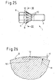
- FIG. 26 illustrates how the pressure surface 8 would run in the area of the flat 10, drawn as a dashed line, the height H of the elevation 12 being dimensioned such that the elevation 12 at its tip contains the dashed envelope curve of the pressure surface 8 only in one Point touches, ie tangent.
- the height H of the elevations 12 determines the pretensioning force or the insertion torque of the elevation 12 on the part to be fastened. Due to a possible deformation of the pressure surface 8 when a correspondingly large pretensioning force or a correspondingly large insertion torque takes effect, an abutment of the elevation 12 on the part to be fastened is also possible if the height H of the elevation 12 is dimensioned such that the elevation 12 dashed envelope of the pressure surface 8 in the unloaded state of the fastener does not touch.
- the elevations 12 and the depressions have a variable height H over their respective longitudinal course or have depth.
- the elevation 12 could each have a height H that the elevation 12 completely in a region of its longitudinal course within the radius of curvature R of the pressure surface 8 (or below the mentioned Envelope) and then increases so that it is in a second area of your Longitudinal course (for example in the sectional plane of Fig. 11) completely the Radius of curvature R of the pressure surface 8 projects beyond. This applies in a complementary manner then for the depression in relation to the radius of curvature of the contact surface.
- the height H of the elevations 12 or depth of the depressions can always be can be chosen such that the elevation 12 at the beginning, in a middle course section, and / or at the end of a screwing-in process of the fastening means 1 only elastic deformation of the elevation 12 itself and / or the component 101 causes, with which the screwing takes place.
- FIG. 27 to 29 illustrate further embodiments of the invention. This is in common that the contour recesses of the fastener 1 by Recesses 14 are formed, the depth T increasing in the direction of rotation E. exhibit. As a result, the efficiency of the increases with increasing torque Contour recesses.
- the contour projections are correspondingly on the component 101 (not shown) formed by increases that increase in the direction of rotation (E) Have height.
- the recesses 14 of the fastening means 1 can be a Have a basic contour that is approximately the shape of a triangle in cross section, preferably has an equilateral triangle, the large cathetus b in the direction of rotation E runs radially inwards, and its small cathete a transverse to the direction of insertion E runs.
- a triangle with hypotenuse c
- Fig. 28 is determined by its corner points A, B, C and will be described in more detail below explained.
- the recesses 14 and Elevations are strip-shaped and essentially rectilinear in the direction of the longitudinal axis of the threaded shaft 2 over the pressure surface 8 or over the contact surface 108.
- edges - e.g. Edge of small catheter a against large cathete b or Edge recess 14 against pressure surface 8 - the contour recesses (in this case of the recesses 14) can either be pointed or also Have roundings, as can be clearly seen in FIGS. 27 and 28.
- the rounded edges guarantee gentle treatment of the components.
- the large catheter b (Fig. 28) of triangular in the basic form Recess 14 formed substantially flat. Between the areas of Pressure area 8, the width of which is designated L1, are the areas of Recesses 14, a substantially over the length of the recesses 14 have constant width, which is designated by L2.
- L1 the width of the two widths L1, L2 is advantageously one Adaptation of the fastening means 1 according to the invention to different ones fastening parts, such as different wheels or rims Motor vehicle types, possible. For example, as shown, come up with one Area of the pressure surface 8 with an average width L1 four immediately following one another arranged recesses 14 with the width L2.
- the seventh embodiment of the invention (lower part of Fig. 27) is one Base 16 of the contour recesses 14 approximately at the level of the radius R Pressure surface 8, so that this in their pressure function - at least at the beginning Screwing process - hardly comes into play.
- the pressure function is in in this case of head points 18 - in analogy to the sixth embodiment - sawtooth-like contour in the transition area from the head 4 to the threaded shaft 2 accepted.
- This contour can then change when screwing in while increasing the Deform loosening torque for the fastener 1 according to the invention, the Dimensioning is carried out according to the invention such that only elastic Deformations (in the area of the so-called Hooke's straight line of the stress-strain diagram) occur, among which according to the invention - as stated above - in particular deformations up to the 0.2% compression limit.
- the deformation is determined when the depth T of the recesses is reached specified torque limit the pressure function of the pressure surface 8 effective again.
- FIG. 28 shows an even more enlarged detail from FIGS. 27 and from the upper part of the drawing (sixth embodiment).
- the recesses 14 advantageously have a basic contour can, which has approximately the shape of an equilateral triangle ABC in cross section.
- the triangular sides a, b, c are drawn with dashed lines.
- the large catheter b des Triangle ABC runs radially inward in the direction of rotation E, preferably in one Angle ⁇ of up to about 30 ° to a tangent t to the pressure surface 8.
- the small one Cathete a runs transverse to the direction of rotation E.
- the large cathete b is slightly curved. Also the Different edges are - as already mentioned above - in the sense of a gentle Material treatment and thus long service life rounded.
- the large cathete b can advantageously have an aspect ratio to the small cathete a from about 3: 1 to about 8: 1 (specifically about 6: 1 in execution). This dimensioning, as well as the above Dimensioning of the angle ⁇ between large cathete b and tangent t, there is an optimally flat course of the large cathete b for screwing in and an optimally steep course of the small ones Cathete a to increase the loosening torque.
- Fastening means 1 is additionally clear that the effective course of the large cathete b of the basic triangle ABC as needed to optimize the Screwing and loosening behavior of the fastener according to the invention also (at least) a curved section b1 and (at least) a flat section b2 can be formed or composed.
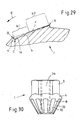
- the embodiment of the invention shown in FIG. 30 differs from all of them remaining in that the fastener 1 is not a bolt, but a Is a mother, there being no shaft 2, but one in the head 4 Threaded bore 2a is located and which is connectable to the fastener 1 Component 101 then has a threaded shaft for the threaded bore 2a.
- the Design of the pressure surface 8 with the flats 10 and also the design the contact surface 108 with the cross-sectional constrictions 110 of the (not shown) Component otherwise corresponds to that of the first embodiment of the invention.
- the invention is not limited to the illustrated embodiments are limited, but also include all in the sense the embodiments having the same effect. So it would be in a not shown Alternatively, for example, it is possible that the contour recesses (flattenings 10, Recesses 14) approximately helical or spiral over the pressure surface 8 run, in particular in a to the release direction of the fastener 1 opposite direction. In addition, it is possible that the contour recesses widen or narrow in the direction of the course.
- - elevations 12 and corresponding Wells are provided, so they do not have to or not exclusively in Area of the contour recesses or the contour projections may be arranged, but can also be located in the area of the pressure surface 8 or the contact surface 108.
- the respective kinematic reversal is also possible, i.e. that the fastening means 1 each have the contour projections 110 as contour jumps and the component 101 as complementary contour jumps, the complementary ones Contour recesses 10, 14 and - if available - the fastener 1 die Wells and component 101 may have elevations 12.
- the invention has not yet been based on the combination of features defined in claim 1 restricted, but can also be limited by any other Combination of certain characteristics of all of the individual characteristics disclosed be defined. This means that basically every single feature of the Claim 1 omitted or by at least one elsewhere Application disclosed single feature can be replaced. In this respect, the claim is 1 to be understood merely as a first attempt at formulating an invention.
Landscapes
- Engineering & Computer Science (AREA)
- General Engineering & Computer Science (AREA)
- Mechanical Engineering (AREA)
- Connection Of Plates (AREA)
- Coupling Device And Connection With Printed Circuit (AREA)
- Clamps And Clips (AREA)
Abstract
Description
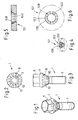
- Fig. 1
- in Perspektivansicht, ein Befestigungsmittel einer ersten Ausführungsform einer erfindungsgemäßen Befestigungsanordnung,
- Fig. 2
- eine gegenüber Fig. 1 vergrößerte Unteransicht auf das in Fig. 1 dargestellte Befestigungsmittel,
- Fig. 3
- eine gegenüber Fig. 1 vergrößerte Seitenansicht des in Fig. 1 dargestellten Befestigungsmittels,
- Fig. 4
- in Fig. 1 entsprechender Darstellung ein mit dem Befestigungsmittel zu verbindendes Bauteil der ersten Ausführungsform einer erfindungsgemäßen Befestigungsanordnung,
- Fig. 5
- eine gegenüber Fig. 4 vergrößerte Schnittdarstellung des in Fig. 4 dargestellten Bauteils,
- Fig. 6
- eine gegenüber Fig. 4 vergrößerte Draufsicht auf das in Fig. 4 dargestellte Bauteil,
- Fig. 7
- in Perspektivansicht, ein Befestigungsmittel einer zweiten Ausführungsform einer erfindungsgemäßen Befestigungsanordnung,
- Fig. 8
- eine Unteransicht auf das in Fig. 7 dargestellte Befestigungsmittel,
- Fig. 9
- eine Seitenansicht des in Fig. 7 dargestellten Befestigungsmittels,
- Fig. 10
- in Fig. 7 entsprechender Darstellung ein mit dem Befestigungsmittel zu verbindendes Bauteil der zweiten Ausführungsform einer erfindungsgemäßen Befestigungsanordnung,
- Fig. 11
- eine Schnittdarstellung des in Fig. 10 dargestellten Bauteils,
- Fig. 12
- eine Draufsicht auf das in Fig. 10 dargestellte Bauteil,
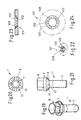
- Fig. 13
- in Perspektivansicht, ein Befestigungsmittel einer dritten Ausführungsform einer erfindungsgemäßen Befestigungsanordnung,
- Fig. 14
- eine gegenüber Fig. 13 vergrößerte Unteransicht auf das in Fig. 13 dargestellte Befestigungsmittel,
- Fig. 15
- eine gegenüber Fig. 13 vergrößerte Seitenansicht des in Fig. 13 dargestellten Befestigungsmittels,
- Fig. 16
- in Fig. 13 entsprechender Darstellung ein mit dem Befestigungsmittel zu verbindendes Bauteil der dritten Ausführungsform einer erfindungsgemäßen Befestigungsanordnung,
- Fig. 17
- eine gegenüber Fig. 16 vergrößerte Schnittdarstellung des in Fig. 15 dargestellten Bauteils,
- Fig. 18
- eine gegenüber Fig. 16 vergrößerte Draufsicht auf das in Fig. 4 dargestellte Bauteil,
- Fig. 19
- in Perspektivansicht, ein Befestigungsmittel einer vierten Ausführungsform einer erfindungsgemäßen Befestigungsanordnung,
- Fig. 20
- eine gegenüber Fig. 19 vergrößerte Unteransicht auf das in Fig. 19 dargestellte Befestigungsmittel,
- Fig. 21
- eine gegenüber Fig. 19 vergrößerte Seitenansicht des in Fig. 13 dargestellten Befestigungsmittels,
- Fig. 22
- in Fig. 19 entsprechender Darstellung ein mit dem Befestigungsmittel zu verbindendes Bauteil der vierten Ausführungsform einer erfindungsgemäßen Befestigungsanordnung,
- Fig. 23
- eine gegenüber Fig. 22 vergrößerte Schnittdarstellung des in Fig. 22 dargestellten Bauteils,
- Fig. 24
- eine gegenüber Fig. 22 vergrößerte Draufsicht auf das in Fig. 22 dargestellte Bauteil,
- Fig. 25
- eine Seitenansicht eines Befestigungsmittels einer fünften Ausführungsform der erfindungsgemäßen Befestigungsanordnung, in Analogie zu Fig. 1, 7, 13 und 19,
- Fig. 26
- eine noch stärker vergrößerte axiale Schnittansicht in Pfeilrichtung XI gemäß Fig. 25,
- Fig. 27
- eine stark vergrößerte axiale Schnittdarstellung eines Befestigungsmittels einer sechsten Ausführungsform (obere Hälfte der Figur) und einer siebenten Ausführungsform (untere Hälfte der Figur) der erfindungsgemäßen Befestigungsanordnung,
- Fig. 28
- ein noch stärker vergrößertes Detail aus Fig. 27,
- Fig. 29
- ein Detail einer axialen Schnittdarstellung eines Befestigungsmittels einer achten Ausführungsform der erfindungsgemäßen Befestigungsanordnüng, analog zu Fig. 28,
- Fig. 30
- eine Seitenansicht eines Befestigungsmittels einer neunten Ausführungsform der erfindungsgemäßen Befestigungsanordnung.
Fig. 26 veranschaulicht diesbezüglich, wie die Andruckfläche 8 im Bereich der Abflachung 10 - als Strichlinie gezeichnet - verlaufen würde, wobei die Höhe H der Erhebung 12 derart bemessen ist, daß die Erhebung 12 an ihrer Spitze die gestrichelte Hüllkurve der Andruckfläche 8 nur in einem Punkt berührt, d.h. tangiert. Die Höhe H der Erhebungen 12 bestimmt, bei welcher Vorspannkraft bzw. bei welchem Eindrehmoment ein Eingriff bzw. eine Anlage der Erhebung 12 an dem zu befestigenden Teil erfolgt. Durch eine mögliche Deformation der Andruckfläche 8 beim Wirksamwerden einer entsprechend großen Vorspannkraft bzw. einem entsprechend großen Eindrehmoment ist dabei auch eine Anlage der Erhebung 12 an dem zu befestigenden Teil möglich, wenn die Höhe H der Erhebung 12 derart bemessen ist, daß die Erhebung 12 die gestrichelte Hüllkurve der Andruckfläche 8 im unbelasteten Zustand des Befestigungsmittels nicht berührt.
- 1
- Befestigungsmittel
- 2
- Gewindeschaft von 1
- 2a
- Gewindebohrung in 1
- 4
- Kopf von 1
- 6
- Kraftangriff an 4
- 8
- Andruckfläche von 1
- 10
- Abflachung (Kontursprung, Konturrücksprung)
- 12
- Erhebung
- 14
- Ausnehmung (Kontursprung, Konturrücksprung)
- 16
- Fußpunkt von 14
- 18
- Kopfpunkt von 14
- 101
- Bauteil
- 102
- Befestigungsloch von 101
- 108
- Anlagefläche von 101
- 110
- Querschnittseinengung (Kontursprung, Konturvorsprung)
- A
- Eckpunkt von ABC
- B
- Eckpunkt von ABC
- C
- Eckpunkt von ABC
- ABC
- Dreieck
- a
- kleine Kathete von ABC
- b
- große Kathete von ABC
- b1
- gekrümmter Abschnitt von b
- b2
- ebener Abschnitt von b
- c
- Hypotenuse von ABC
- E
- Eindrehrichtung von 1
- H
- Höhe von 12
- L1
- Breite von 8
- L2
- Breite von 14
- R
- Krümmungsradius vom 8
- T
- Tiefe von 14
- t
- Tangente an 8
- a
- Winkel zwischen b und t
Claims (26)
- Befestigungsanordnung, umfassend einerseits ein Befestigungsmittel (1), das einen Kopf (4) mit einem Kraftangriff (6) für ein Drehwerkzeug und mit einer konisch oder kalottenartig gekrümmten Andruckfläche (8) aufweist, in deren Bereich mehrere über ihren Umfang verteilt angeordnete und ihre eigentliche Flächenkrümmung unterbrechende Kontursprünge (Konturrücksprünge 10, 14 oder Konturvorsprünge 110) gebildet sind, und umfassend andererseits ein mit dem Befestigungsmittel (1) verbindbares Bauteil (101), das eine konisch oder kalottenartig gekrümmte Anlagefläche (108) für die Andruckfläche (8) des Befestigungsmittels (1) aufweist,
dadurch gekennzeichnet, daß im Bereich der Anlagefläche (108) mehrere über ihren Umfang verteilt angeordnete und ihre eigentliche Flächenkrümmung unterbrechende Gegenkontursprünge (Konturvorsprünge 110 oder Konturrücksprünge 10, 14) gebildet sind, die im verbundenen Zustand von Befestigungsmittel (1) und Bauteil (101) formschlüssig in die Kontursprünge (10, 14, 110) der Andruckfläche (8) eingreifen, wobei die Andruckfläche (8) mit den Kontursprüngen (10, 14, 110) und die Anlagefläche (108) mit den Gegenkontursprüngen (110, 10, 14) derart dimensioniert sind, daß beim Verbinden von Befestigungsmittel (1) und Bauteil (101) keine bleibenden, makroskopischen Formänderungen auftreten. - Befestigungsanordnung nach Anspruch 1,
dadurch gekennzeichnet, daß die Kontursprünge (10, 14, 110) streifenförmig und im wesentlichen geradlinig in Richtung der Längsachse des Gewindeschaftes (2) über die Andruckfläche (8) verlaufen und daß die Gegenkontursprünge (110, 10, 14) streifenförmig und im wesentlichen geradlinig in Richtung der Längsachse des Befestigungsloches (102) über die Anlagefläche (108) verlaufen. - Befestigungsanordnung nach Anspruch 1,
dadurch gekennzeichnet, daß die Kontursprünge (10, 14, 110) streifenförmig und etwa schraubenlinienförmig oder spiralförmig über die Andruckfläche (8) verlaufen, und zwar insbesondere in zur Lösedrehrichtung entgegengesetzter Verlaufsrichtung (Eindrehrichtung E) und daß die Gegenkontursprünge (110, 10, 14) streifenförmig und etwa schraubenlinienförmig oder spiralförmig über die Anlagefläche (108) verlaufen. - Befestigungsanordnung nach einem der Ansprüche 1 bis 3,
dadurch gekennzeichnet, daß die Kontursprünge (10, 14, 110) und die Gegenkonturvorsprünge (110, 10, 14) sich in ihrer Verlaufsrichtung jeweils verbreitern oder verschmälern. - Befestigungsanordnung nach einem der Ansprüche 1 bis 4,
dadurch gekennzeichnet, daß Kanten der Kontursprünge (10, 14, 110) und der Gegenkontursprünge (110, 10, 14) spitz ausgebildet sind. - Befestigungsanordnung nach einem der Ansprüche 1 bis 5,
dadurch gekennzeichnet, daß Kanten der Kontursprünge (10, 14, 110) und der Gegenkontursprünge (110, 10, 14) Abrundungen aufweisen. - Befestigungsanordnung nach einem der Ansprüche 1 bis 6,
dadurch gekennzeichnet, daß mindestens drei, insbesondere etwa vier bis sechzehn, Kontursprünge (10, 14, 110) und Gegenkontursprünge (110, 10, 14) vorgesehen sind. - Befestigungsanordnung nach einem der Ansprüche 1 bis 7,
dadurch gekennzeichnet, daß die Kontursprünge (10, 14, 110) durch Abflachungen (10) und die Gegenkonturvorsprünge (110, 10, 14) durch Aufwölbungen auf der Anlagefläche (108) oder Querschnittseinengungen (110) des Befestigungsloches (102) gebildet sind, oder umgekehrt. - Befestigungsanordnung nach Anspruch 8,
dadurch gekennzeichnet, daß jede Abflachung (10) und die korrespondierende Querschnittseinengung (110) im wesentlichen eben oder jede Abflachung (10) und die korrespondierende Aufwölbung schwach gekrümmt mit einem Krümmungsradius ausgebildet ist, der größer als der entsprechende Krümmungsradius (R) der Andruckfläche (8) bzw. der Anlagefläche (108) ist. - Befestigungsanordnung nach einem der Ansprüche 1 bis 7,
dadurch gekennzeichnet, daß die Kontursprünge (10, 14, 110) durch Ausnehmungen (14) gebildet sind, die eine in Eindrehrichtung (E) zunehmende Tiefe (T) aufweisen und daß die Gegenkontursprünge (110) durch Erhöhungen gebildet sind, die eine in Eindrehrichtung (E) zunehmende Höhe aufweisen, oder umgekehrt. - Befestigungsanordnung nach Anspruch 10,
dadurch gekennzeichnet, daß die Ausnehmungen (14) und Erhöhungen jeweils eine Grundkontur aufweisen, die im Querschnitt etwa die Form eines ungleichseitigen Dreiecks (ABC) besitzt, dessen große Kathete (b) in Eindrehrichtung (E) radial nach innen verläuft, vorzugsweise in einem Winkel (α) von bis zu etwa 30° zu einer Tangente (t) an die Andruckfläche (8), und dessen kleine Kathete (a) quer zur Eindrehrichtung (E) verläuft. - Befestigungsanordnung nach Anspruch 11,
dadurch gekennzeichnet, daß die große Kathete (b) im wesentlichen eben oder schwach gekrümmt ausgebildet ist und/oder aus ebenen Abschnitten (b2) und gekrümmten Abschnitten (b1) zusammengesetzt ist. - Befestigungsanordnung nach Anspruch 11 oder 12,
dadurch gekennzeichnet, daß die große Kathete (b) zur kleinen Kathete (a) in einem Längenverhältnis von etwa 3 : 1 bis zu etwa 8 : 1 steht. - Befestigungsanordnung nach einem der Ansprüche 1 bis 13,
dadurch gekennzeichnet, daß im Bereich der Andruckfläche (8) oder im Bereich der Kontursprünge (10, 14, 110) mindestens eine Erhebung (12) oder Vertiefung, vorzugsweise mehrere Erhebungen (12) oder Vertiefungen, angeordnet ist/sind und daß im Bereich der Anlagefläche (108) oder im Bereich der Gegenkontursprünge (110, 10, 14) mindestens eine komplementäre Vertiefung, oder Erhebung, vorzugsweise mehrere Vertiefungen oder Erhebungen, angeordnet ist/sind, wobei die Erhebungen (12) im verbundenen Zustand von Befestigungsmittel (1) und Bauteil (101) formschlüssig in die Vertiefungen eingreifen, und die Erhebungen (12) und Vertiefungen derart dimensioniert sind, daß beim Verbinden von Befestigungsmittel (1) und Bauteil (101) keine bleibenden Formänderungen auftreten. - Befestigungsanordnung nach Anspruch 14,
dadurch gekennzeichnet, daß die Erhebung (12) im Hautrelief und die Vertiefung im Basrelief jeweils etwa halbkugelförmig oder als Kugelkappe ausgebildet ist oder zumindest einen halbkreisförmigen oder kreisabschnittförmigen Querschnitt aufweist. - Befestigungsanordnung nach Anspruch 14,
dadurch gekennzeichnet, daß die Erhebung (12) jeweils als Rippe ausgebildet ist, die dem Grundverlauf der Kontursprünge (10, 14, 110) oder Gegenkontursprünge (110, 10, 14) folgt und daß die Vertiefung jeweils als Nut ausgebildet ist, die dem Grundverlauf der Gegenkontursprünge (110, 10, 14) oder der Kontursprünge (10, 14, 110) folgt. - Befestigungsanordnung nach einem der Ansprüche 14 bis 16,
dadurch gekennzeichnet, daß sich die Erhebung (12) jeweils als eine Anzahl von mehreren Teilerhebungen oder als Ganzes über die gesamte Länge der Kontursprünge (10, 14, 110) oder der Gegenkontursprünge (110, 10, 14) erstreckt und daß sich die Vertiefung jeweils als eine Anzahl von mehreren Teilvertiefungen oder als Ganzes über die gesamte Länge der Gegenkontursprünge (110, 10, 14) oder der Kontursprünge (10, 14, 110) erstreckt. - Befestigungsanordnung nach einem der Ansprüche 14 bis 16,
dadurch gekennzeichnet, daß sich die Erhebung (12) oder die Vertiefung jeweils als eine Anzahl von mehreren Teilerhebungen oder Teilvertiefungen oder als Ganzes über eine Teillänge der Konturrücksprünge (10, 14, 110), insbesondere über deren kopfseitige oder schaftseitige Hälfte, und daß sich die Vertiefung oder die Erhebung jeweils als eine Anzahl von mehreren Teilvertiefungen oder Teilerhebungen als Ganzes über eine Teillänge der Gegenkontursprünge (110, 10, 14), insbesondere über eine obere oder untere Hälfte, erstreckt. - Befestigungsanordnung nach einem der Ansprüche 14 bis 18,
dadurch gekennzeichnet, daß die Erhebung (12) zumindest bereichsweise den Krümmungsradius (R) der Andruckfläche (8) tangiert oder überragt und daß die Vertiefung zumindest bereichsweise den Krümmungsradius (R) der Anlagefläche (108) tangiert oder durchdringt. - Befestigungsanordnung nach einem der Ansprüche 14 bis 19,
dadurch gekennzeichnet, daß die Erhebung (12) und die Vertiefung über ihren jeweiligen Längsverlauf eine veränderliche Höhe (H) bzw. Tiefe aufweisen. - Befestigungsanordnung nach einem der Ansprüche 1 bis 20,
dadurch gekennzeichnet, daß eine maximale jeweilige Abmessung (Tiefe T oder Höhe) der Kontursprünge (10, 14, 110) gegenüber der Andruckfläche (8) und eine jeweilige maximale Gegenabmessung (Höhe oder Tiefe) der Gegenkontursprünge (110, 10, 14) gegenüber der Anlagefläche (108) sowie die jeweilige Höhe (H) gegebenenfalls vorhandener Erhebungen (12) und die jeweilige Tiefe gegebenenfalls vorhandener Vertiefungen zumindest unter Beachtung der jeweiligen, aus dem Druckversuch nach DIN 50 106 gewonnenen Quetschgrenzen RdF der Werkstoffe des Befestigungsmittels (1) und des Bauteils (101), vorzugsweise aber unter Beachtung der jeweiligen 0,2%-Stauchgrenze Rd0,2, dimensioniert sind, wobei hinsichtlich dieser Kenngrößen der Werkstoffe von Befestigungsmittel (1) und Bauteil (101) der jeweils kleinere Wert zugrundegelegt ist. - Befestigungsanordnung nach einem der Ansprüche 1 bis 21,
dadurch gekennzeichnet, daß das Befestigungsmittel (1) ein Schraubbolzen ist, der einen Gewindeschaft (2) aufweist, an dessen einem Ende der Kopf (4) ausgebildet ist, wobei die konisch oder kalottenartig gekrümmte Andruckfläche (8) in einem Übergangsbereich des Kopfes (4) zu dem Gewindeschaft (2) hin angeordnet ist und wobei das mit dem Befestigungsmittel (1) verbindbare Bauteil ein Befestigungsloch (102) für den Gewindeschaft (2) aufweist. - Befestigungsanordnung nach einem der Ansprüche 1 bis 21,
dadurch gekennzeichnet, daß das Befestigungsmittel (1) eine Mutter ist, wobei sich in dem Kopf (4) eine Gewindebohrung (2a) befindet und
wobei das mit dem Befestigungsmittel (1) verbindbare Bauteil (101) einen Gewindeschaft für die Gewindebohrung (2a) aufweist. - Befestigungsanordnung nach einem der Ansprüche 1 bis 23,
dadurch gekennzeichnet, daß das Befestigungsmittel (1) und/oder das Bauteil (101) mit einer antiadhäsiven, tribologisch wirksamen Beschichtung versehen sind/ist, welche insbesondere den Verschleiß durch eine Verminderung der Gefahr des Fressens herabsetzt. - Befestigungsmittel, wie eine Radschraube, einer Befestigungsanordnung, die einerseits das Befestigungsmittel (1) umfaßt, das einen Kopf (4) mit einem Kraftangriff (6) für ein Drehwerkzeug und mit einer konisch oder kalottenartig gekrümmten Andruckfläche (8) aufweist, in deren Bereich mehrere über ihren Umfang verteilt angeordnete und ihre eigentliche Flächenkrümmung unterbrechende Kontursprünge (Konturrücksprünge 10, 14 oder Konturvorsprünge 110) gebildet sind, und die andererseits ein mit dem Befestigungsmittel (1) verbindbares Bauteil (101) umfaßt, das eine konisch oder kalottenartig gekrümmte Anlagefläche (108) für die Andruckfläche (8) des Befestigungsmittels (1) aufweist, wobei im Bereich der Anlagefläche (108) mehrere über ihren Umfang verteilt angeordnete und ihre eigentliche Flächenkrümmung unterbrechende Gegenkontursprünge (Konturvorsprünge 110 oder Konturrücksprünge 10, 14) gebildet sind, die dazu bestimmt sind, im verbundenen Zustand von Befestigungsmittel (1) und Bauteil (101) formschlüssig in die Kontursprünge (10, 14, 110) der Andruckfläche (8) einzugreifen, wobei die Andruckfläche (8) mit den Kontursprüngen (10, 14, 110) und die Anlagefläche (108) mit den Gegenkontursprüngen (110, 10, 14) derart dimensioniert sind, daß beim Verbinden von Befestigungsmittel (1) und Bauteil (101) keine bleibenden makroskopischen Formänderungen auftreten, und wobei die Andruckfläche (8) des Befestigungsmittels (1) komplementär zur Anlagefläche (108) des Bauteils (101) ausgebildet ist.
- Bauteil, wie eine Radfelge, einer Befestigungsanordnung, die einerseits ein Befestigungsmittel (1) umfaßt, das einen Kopf (4) mit einem Kraftangriff (6) für ein Drehwerkzeug und mit einer konisch oder kalottenartig gekrümmten Andruckfläche (8) aufweist, in deren Bereich mehrere über ihren Umfang verteilt angeordnete und ihre eigentliche Flächenkrümmung unterbrechende Kontursprünge (Konturrücksprünge 10, 14 oder Konturvorsprünge110) gebildet sind, und die andererseits das mit dem Befestigungsmittel (1) verbindbare Bauteil (101) umfaßt, das eine konisch oder kalottenartig gekrümmte Anlagefläche (108) für die Andruckfläche (8) des Befestigungsmittels (1) aufweist, wobei im Bereich der Anlagefläche (108) mehrere über ihren Umfang verteilt angeordnete und ihre eigentliche Flächenkrümmung unterbrechende Gegenkontursprünge (Konturvorsprünge 110 oder Konturrücksprünge 10, 14) gebildet sind, die dazu bestimmt sind, im verbundenen Zustand von Befestigungsmittel (1) und Bauteil (101) formschlüssig in die Kontursprünge (10, 14, 110) der Andruckfläche (8) einzugreifen, wobei die Andruckfläche (8) mit den Kontursprüngen (10, 14, 110) und die Anlagefläche (108) mit den Gegenkontursprüngen (110, 10, 14) derart dimensioniert sind, daß beim Verbinden von Befestigungsmittel (1) und Bauteil (101) keine bleibenden makroskopischen Formänderungen auftreten, und wobei die Anlagefläche (108) des Bauteils (101) komplemetär zur Andruckfläche (8) des Befestigungsmittels (1) ausgebildet ist.
Applications Claiming Priority (2)
| Application Number | Priority Date | Filing Date | Title |
|---|---|---|---|
| DE20204556U | 2002-03-22 | ||
| DE20204556U DE20204556U1 (de) | 2002-03-22 | 2002-03-22 | Befestigungsanordnung |
Publications (2)
| Publication Number | Publication Date |
|---|---|
| EP1350969A1 true EP1350969A1 (de) | 2003-10-08 |
| EP1350969B1 EP1350969B1 (de) | 2005-07-27 |
Family
ID=7969253
Family Applications (1)
| Application Number | Title | Priority Date | Filing Date |
|---|---|---|---|
| EP03006267A Expired - Lifetime EP1350969B1 (de) | 2002-03-22 | 2003-03-21 | Befestigungsanordnung |
Country Status (4)
| Country | Link |
|---|---|
| EP (1) | EP1350969B1 (de) |
| AT (1) | ATE300680T1 (de) |
| DE (2) | DE20204556U1 (de) |
| ES (1) | ES2242912T3 (de) |
Cited By (2)
| Publication number | Priority date | Publication date | Assignee | Title |
|---|---|---|---|---|
| ES2258900A1 (es) * | 2004-07-27 | 2006-09-01 | Fominaya, S.A. | Sistema para bloqueo de elementos de regulacion de una cisterna. |
| EP1923513A4 (de) * | 2005-08-26 | 2013-07-10 | Fominaya Sa | System zum blockieren der bewegung von regulierungselementen in spülkästen |
Families Citing this family (2)
| Publication number | Priority date | Publication date | Assignee | Title |
|---|---|---|---|---|
| DE102007043705A1 (de) * | 2007-09-13 | 2009-03-19 | Dr. Hahn Gmbh & Co. Kg | Montageschraube und Befestigungsanordnung mit einem Hohlkammerprofil |
| WO2024224278A1 (en) * | 2023-04-24 | 2024-10-31 | Maxion Wheels Holding Gmbh | An arrangement for securing a screw connection element, and screw connection element usable in the arrangement |
Citations (2)
| Publication number | Priority date | Publication date | Assignee | Title |
|---|---|---|---|---|
| DE29914357U1 (de) * | 1999-01-27 | 2000-08-10 | Hagedorn, Klaus, 58097 Hagen | Befestigungsmittel |
| WO2001066964A1 (en) * | 2000-03-09 | 2001-09-13 | Hanna Maria Smolarek | Washer and threaded fastener assembly incorporating same |
-
2002
- 2002-03-22 DE DE20204556U patent/DE20204556U1/de not_active Expired - Lifetime
-
2003
- 2003-03-21 EP EP03006267A patent/EP1350969B1/de not_active Expired - Lifetime
- 2003-03-21 AT AT03006267T patent/ATE300680T1/de not_active IP Right Cessation
- 2003-03-21 DE DE50300831T patent/DE50300831D1/de not_active Expired - Lifetime
- 2003-03-21 ES ES03006267T patent/ES2242912T3/es not_active Expired - Lifetime
Patent Citations (2)
| Publication number | Priority date | Publication date | Assignee | Title |
|---|---|---|---|---|
| DE29914357U1 (de) * | 1999-01-27 | 2000-08-10 | Hagedorn, Klaus, 58097 Hagen | Befestigungsmittel |
| WO2001066964A1 (en) * | 2000-03-09 | 2001-09-13 | Hanna Maria Smolarek | Washer and threaded fastener assembly incorporating same |
Cited By (3)
| Publication number | Priority date | Publication date | Assignee | Title |
|---|---|---|---|---|
| ES2258900A1 (es) * | 2004-07-27 | 2006-09-01 | Fominaya, S.A. | Sistema para bloqueo de elementos de regulacion de una cisterna. |
| ES2258900B1 (es) * | 2004-07-27 | 2008-03-01 | Fominaya, S.A. | Sistema para bloqueo de elementos de regulacion de una cisterna. |
| EP1923513A4 (de) * | 2005-08-26 | 2013-07-10 | Fominaya Sa | System zum blockieren der bewegung von regulierungselementen in spülkästen |
Also Published As
| Publication number | Publication date |
|---|---|
| ES2242912T3 (es) | 2005-11-16 |
| DE50300831D1 (de) | 2005-09-01 |
| ATE300680T1 (de) | 2005-08-15 |
| DE20204556U1 (de) | 2002-07-04 |
| EP1350969B1 (de) | 2005-07-27 |
Similar Documents
| Publication | Publication Date | Title |
|---|---|---|
| DE3610392C2 (de) | Schraube für verunreinigte Gewindebohrungen | |
| EP0869287B1 (de) | Selbtlochendes und gewindeformendes Verbindungselement | |
| DE2452825C2 (de) | Schraube | |
| DE4307090B4 (de) | Mutter, insbesondere Radmutter | |
| WO2005080802A1 (de) | Gewindeformende schraube | |
| WO2014191310A1 (de) | Schraube | |
| EP2806174A1 (de) | Schraubelement | |
| DE4333791A1 (de) | Gewindeschneidschraube | |
| EP1591675A2 (de) | Verbindungsanordnung mit einem Kunststoff-Trägerteil und einem Kunststoff-Gewindeelement | |
| EP1031742B1 (de) | Senkkopfschraube | |
| EP3405686B1 (de) | Kunststoff-gewindeelement sowie verbindungsanordnung bestehend aus einem kunststoffträgerteil und einem kunststoff-gewindeelement | |
| DE69607462T2 (de) | Selbstsichernde Mutter | |
| DE2457143B2 (de) | Sicherungsschraube | |
| EP1718876A1 (de) | Gewindeformende schraube | |
| EP1903223B1 (de) | Mutter aus Kunststoff | |
| DE1500792A1 (de) | Gewindebefestigungsanordnung | |
| EP1291535B1 (de) | Sicherungsmutter und Verfahren zur ihrer Herstellung | |
| EP3721102A1 (de) | Zweiteilige schraubenmutter mit hoher andrückkraft | |
| EP1350969B1 (de) | Befestigungsanordnung | |
| DE4307092B4 (de) | Mutter, insbesondere Radmutter | |
| EP3404273B1 (de) | Schraubelement | |
| AT391747B (de) | Rohrschelle | |
| EP2044341A1 (de) | Sicherungsmutter | |
| DE4307091B4 (de) | Mutter, insbesondere Radmutter | |
| DE102017219160A1 (de) | Schraube zum Einschrauben in ein Bohrloch |
Legal Events
| Date | Code | Title | Description |
|---|---|---|---|
| PUAI | Public reference made under article 153(3) epc to a published international application that has entered the european phase |
Free format text: ORIGINAL CODE: 0009012 |
|
| AK | Designated contracting states |
Kind code of ref document: A1 Designated state(s): AT BE BG CH CY CZ DE DK EE ES FI FR GB GR HU IE IT LI LU MC NL PT RO SE SI SK TR |
|
| AX | Request for extension of the european patent |
Extension state: AL LT LV MK RO |
|
| 17P | Request for examination filed |
Effective date: 20040317 |
|
| 17Q | First examination report despatched |
Effective date: 20040504 |
|
| AKX | Designation fees paid |
Designated state(s): AT BE BG CH CY CZ DE DK EE ES FI FR GB GR HU IE IT LI LU MC NL PT RO SE SI SK TR |
|
| GRAP | Despatch of communication of intention to grant a patent |
Free format text: ORIGINAL CODE: EPIDOSNIGR1 |
|
| GRAS | Grant fee paid |
Free format text: ORIGINAL CODE: EPIDOSNIGR3 |
|
| GRAA | (expected) grant |
Free format text: ORIGINAL CODE: 0009210 |
|
| REG | Reference to a national code |
Ref country code: SE Ref legal event code: TRGR |
|
| AK | Designated contracting states |
Kind code of ref document: B1 Designated state(s): AT BE BG CH CY CZ DE DK EE ES FI FR GB GR HU IE IT LI LU MC NL PT RO SE SI SK TR |
|
| PG25 | Lapsed in a contracting state [announced via postgrant information from national office to epo] |
Ref country code: SK Free format text: LAPSE BECAUSE OF FAILURE TO SUBMIT A TRANSLATION OF THE DESCRIPTION OR TO PAY THE FEE WITHIN THE PRESCRIBED TIME-LIMIT Effective date: 20050727 Ref country code: IE Free format text: LAPSE BECAUSE OF FAILURE TO SUBMIT A TRANSLATION OF THE DESCRIPTION OR TO PAY THE FEE WITHIN THE PRESCRIBED TIME-LIMIT Effective date: 20050727 Ref country code: RO Free format text: LAPSE BECAUSE OF FAILURE TO SUBMIT A TRANSLATION OF THE DESCRIPTION OR TO PAY THE FEE WITHIN THE PRESCRIBED TIME-LIMIT Effective date: 20050727 Ref country code: EE Free format text: LAPSE BECAUSE OF FAILURE TO SUBMIT A TRANSLATION OF THE DESCRIPTION OR TO PAY THE FEE WITHIN THE PRESCRIBED TIME-LIMIT Effective date: 20050727 Ref country code: SI Free format text: LAPSE BECAUSE OF FAILURE TO SUBMIT A TRANSLATION OF THE DESCRIPTION OR TO PAY THE FEE WITHIN THE PRESCRIBED TIME-LIMIT Effective date: 20050727 Ref country code: TR Free format text: LAPSE BECAUSE OF FAILURE TO SUBMIT A TRANSLATION OF THE DESCRIPTION OR TO PAY THE FEE WITHIN THE PRESCRIBED TIME-LIMIT Effective date: 20050727 Ref country code: FI Free format text: LAPSE BECAUSE OF FAILURE TO SUBMIT A TRANSLATION OF THE DESCRIPTION OR TO PAY THE FEE WITHIN THE PRESCRIBED TIME-LIMIT Effective date: 20050727 |
|
| REG | Reference to a national code |
Ref country code: GB Ref legal event code: FG4D Free format text: NOT ENGLISH |
|
| REG | Reference to a national code |
Ref country code: CH Ref legal event code: EP |
|
| REG | Reference to a national code |
Ref country code: IE Ref legal event code: FG4D Free format text: LANGUAGE OF EP DOCUMENT: GERMAN |
|
| REF | Corresponds to: |
Ref document number: 50300831 Country of ref document: DE Date of ref document: 20050901 Kind code of ref document: P |
|
| PG25 | Lapsed in a contracting state [announced via postgrant information from national office to epo] |
Ref country code: BG Free format text: LAPSE BECAUSE OF FAILURE TO SUBMIT A TRANSLATION OF THE DESCRIPTION OR TO PAY THE FEE WITHIN THE PRESCRIBED TIME-LIMIT Effective date: 20051027 Ref country code: DK Free format text: LAPSE BECAUSE OF FAILURE TO SUBMIT A TRANSLATION OF THE DESCRIPTION OR TO PAY THE FEE WITHIN THE PRESCRIBED TIME-LIMIT Effective date: 20051027 Ref country code: GR Free format text: LAPSE BECAUSE OF FAILURE TO SUBMIT A TRANSLATION OF THE DESCRIPTION OR TO PAY THE FEE WITHIN THE PRESCRIBED TIME-LIMIT Effective date: 20051027 |
|
| REG | Reference to a national code |
Ref country code: SE Ref legal event code: RPOT |
|
| REG | Reference to a national code |
Ref country code: ES Ref legal event code: FG2A Ref document number: 2242912 Country of ref document: ES Kind code of ref document: T3 |
|
| GBT | Gb: translation of ep patent filed (gb section 77(6)(a)/1977) |
Effective date: 20051028 |
|
| PG25 | Lapsed in a contracting state [announced via postgrant information from national office to epo] |
Ref country code: PT Free format text: LAPSE BECAUSE OF FAILURE TO SUBMIT A TRANSLATION OF THE DESCRIPTION OR TO PAY THE FEE WITHIN THE PRESCRIBED TIME-LIMIT Effective date: 20051227 |
|
| PG25 | Lapsed in a contracting state [announced via postgrant information from national office to epo] |
Ref country code: HU Free format text: LAPSE BECAUSE OF FAILURE TO SUBMIT A TRANSLATION OF THE DESCRIPTION OR TO PAY THE FEE WITHIN THE PRESCRIBED TIME-LIMIT Effective date: 20060128 |
|
| REG | Reference to a national code |
Ref country code: IE Ref legal event code: FD4D |
|
| PG25 | Lapsed in a contracting state [announced via postgrant information from national office to epo] |
Ref country code: AT Free format text: LAPSE BECAUSE OF NON-PAYMENT OF DUE FEES Effective date: 20060321 |
|
| PG25 | Lapsed in a contracting state [announced via postgrant information from national office to epo] |
Ref country code: MC Free format text: LAPSE BECAUSE OF NON-PAYMENT OF DUE FEES Effective date: 20060331 Ref country code: BE Free format text: LAPSE BECAUSE OF NON-PAYMENT OF DUE FEES Effective date: 20060331 Ref country code: LU Free format text: LAPSE BECAUSE OF NON-PAYMENT OF DUE FEES Effective date: 20060331 |
|
| ET | Fr: translation filed | ||
| PLBE | No opposition filed within time limit |
Free format text: ORIGINAL CODE: 0009261 |
|
| STAA | Information on the status of an ep patent application or granted ep patent |
Free format text: STATUS: NO OPPOSITION FILED WITHIN TIME LIMIT |
|
| 26N | No opposition filed |
Effective date: 20060428 |
|
| REG | Reference to a national code |
Ref country code: CH Ref legal event code: PL |
|
| BERE | Be: lapsed |
Owner name: ALTENLOH, BRINCK & CO. G.M.B.H. & CO. KG Effective date: 20060331 |
|
| PG25 | Lapsed in a contracting state [announced via postgrant information from national office to epo] |
Ref country code: CH Free format text: LAPSE BECAUSE OF NON-PAYMENT OF DUE FEES Effective date: 20070331 Ref country code: LI Free format text: LAPSE BECAUSE OF NON-PAYMENT OF DUE FEES Effective date: 20070331 |
|
| PGFP | Annual fee paid to national office [announced via postgrant information from national office to epo] |
Ref country code: ES Payment date: 20080207 Year of fee payment: 6 |
|
| PGFP | Annual fee paid to national office [announced via postgrant information from national office to epo] |
Ref country code: CZ Payment date: 20080128 Year of fee payment: 6 Ref country code: GB Payment date: 20080326 Year of fee payment: 6 Ref country code: IT Payment date: 20080125 Year of fee payment: 6 Ref country code: NL Payment date: 20080325 Year of fee payment: 6 Ref country code: SE Payment date: 20080306 Year of fee payment: 6 |
|
| PGFP | Annual fee paid to national office [announced via postgrant information from national office to epo] |
Ref country code: FR Payment date: 20080311 Year of fee payment: 6 |
|
| PG25 | Lapsed in a contracting state [announced via postgrant information from national office to epo] |
Ref country code: CY Free format text: LAPSE BECAUSE OF FAILURE TO SUBMIT A TRANSLATION OF THE DESCRIPTION OR TO PAY THE FEE WITHIN THE PRESCRIBED TIME-LIMIT Effective date: 20050727 |
|
| PG25 | Lapsed in a contracting state [announced via postgrant information from national office to epo] |
Ref country code: CZ Free format text: LAPSE BECAUSE OF NON-PAYMENT OF DUE FEES Effective date: 20090321 |
|
| EUG | Se: european patent has lapsed | ||
| GBPC | Gb: european patent ceased through non-payment of renewal fee |
Effective date: 20090321 |
|
| NLV4 | Nl: lapsed or anulled due to non-payment of the annual fee |
Effective date: 20091001 |
|
| PG25 | Lapsed in a contracting state [announced via postgrant information from national office to epo] |
Ref country code: NL Free format text: LAPSE BECAUSE OF NON-PAYMENT OF DUE FEES Effective date: 20091001 |
|
| PG25 | Lapsed in a contracting state [announced via postgrant information from national office to epo] |
Ref country code: GB Free format text: LAPSE BECAUSE OF NON-PAYMENT OF DUE FEES Effective date: 20090321 |
|
| REG | Reference to a national code |
Ref country code: ES Ref legal event code: FD2A Effective date: 20090323 |
|
| PG25 | Lapsed in a contracting state [announced via postgrant information from national office to epo] |
Ref country code: ES Free format text: LAPSE BECAUSE OF NON-PAYMENT OF DUE FEES Effective date: 20090323 |
|
| REG | Reference to a national code |
Ref country code: FR Ref legal event code: ST Effective date: 20100831 |
|
| PG25 | Lapsed in a contracting state [announced via postgrant information from national office to epo] |
Ref country code: FR Free format text: LAPSE BECAUSE OF NON-PAYMENT OF DUE FEES Effective date: 20090331 |
|
| PG25 | Lapsed in a contracting state [announced via postgrant information from national office to epo] |
Ref country code: IT Free format text: LAPSE BECAUSE OF NON-PAYMENT OF DUE FEES Effective date: 20090321 |
|
| PG25 | Lapsed in a contracting state [announced via postgrant information from national office to epo] |
Ref country code: SE Free format text: LAPSE BECAUSE OF NON-PAYMENT OF DUE FEES Effective date: 20090322 |
|
| REG | Reference to a national code |
Ref country code: DE Ref legal event code: R082 Ref document number: 50300831 Country of ref document: DE Representative=s name: PATENTANWAELTE BECKER & MUELLER, DE |
|
| REG | Reference to a national code |
Ref country code: DE Ref legal event code: R082 Ref document number: 50300831 Country of ref document: DE Representative=s name: PATENTANWAELTE BECKER & MUELLER, DE Ref country code: DE Ref legal event code: R081 Ref document number: 50300831 Country of ref document: DE Owner name: ABC UMFORMTECHNIK GMBH & CO. KOMMANDITGESELLSC, DE Free format text: FORMER OWNER: ALTENLOH, BRINCK & CO GMBH & CO KG, 58256 ENNEPETAL, DE |
|
| PGFP | Annual fee paid to national office [announced via postgrant information from national office to epo] |
Ref country code: DE Payment date: 20220328 Year of fee payment: 20 |
|
| REG | Reference to a national code |
Ref country code: DE Ref legal event code: R071 Ref document number: 50300831 Country of ref document: DE |