EP1351024A2 - Abzugshaube für Einbau - Google Patents
Abzugshaube für Einbau Download PDFInfo
- Publication number
- EP1351024A2 EP1351024A2 EP03075932A EP03075932A EP1351024A2 EP 1351024 A2 EP1351024 A2 EP 1351024A2 EP 03075932 A EP03075932 A EP 03075932A EP 03075932 A EP03075932 A EP 03075932A EP 1351024 A2 EP1351024 A2 EP 1351024A2
- Authority
- EP
- European Patent Office
- Prior art keywords
- built
- aspirating hood
- aspirating
- hood according
- fumes
- Prior art date
- Legal status (The legal status is an assumption and is not a legal conclusion. Google has not performed a legal analysis and makes no representation as to the accuracy of the status listed.)
- Withdrawn
Links
Images


Classifications
-
- F—MECHANICAL ENGINEERING; LIGHTING; HEATING; WEAPONS; BLASTING
- F24—HEATING; RANGES; VENTILATING
- F24C—DOMESTIC STOVES OR RANGES ; DETAILS OF DOMESTIC STOVES OR RANGES, OF GENERAL APPLICATION
- F24C15/00—Details
- F24C15/20—Removing cooking fumes
- F24C15/2042—Devices for removing cooking fumes structurally associated with a cooking range e.g. downdraft
Definitions
- the present invention refers to an aspirating hood to be built into a wall.
- a first way is a small distance above the cooking surface, for example about 65 cm. This is the most widespread installation, because it is the most traditional and the easiest to construct. It is effective, but rather awkward, because it is necessary to give particular attention to not banging one's head against the lower edge or the side rims of the aspirating hood and often it is necessary to twist one's body.
- a second way is that on an island at the centre of the room. It is an installation which is similar to the one indicated previously and thus it keeps the advantages and defects thereof.
- a third example is that of an aspirating hood integrated in the lower or base furniture.
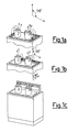
- This installation known and widespread in the USA, going by the name of "down draft" (shown in figures 1a, 1b) foresees the presence of one or more grated suction zones, at the cooking surface level, to the right, left or behind, through which the fumes and vapours are sucked by a fan which is necessarily very powerful, and thus noisy, positioned inside the base.
- the suction power must be high because the flow of air must be deviated downwards, against its natural tendency to rise, with greater suction needed the hotter the airflow.
- a telescopic boxed element (figure 1c), having an inlet opening for the air on its upper front part.
- This element extends electrically-driven from the surface of the base by about 20 cm, so as to reduce the deviation downwards of the flow of fumes and vapours.
- the general purpose of the present invention is therefore that of identifying an optimal solution to the aforementioned technical problems.
- a purpose of the present invention is that of realising an aspirating hood which allows great freedom of movement and which has maximum ergonomics in use of the cooking zone. Indeed, we must try to eliminate all possible situations of risk of knocking the head of average and tall operators and situations of discomfort due to awkward movements when instinctively one goes to check how the cooking is coming along.
- An aspirating hood according to the invention is preferably applied into the thickness of the walls of a home, inside the kitchen space, or else, alternatively, also inside furniture.
- This aspirating hood must be positioned at the cooking surface, on the vertical masonry wall or inside the furniture arranged immediately behind the cooking surface itself, so as to be in the best conditions for sucking up the vapours and fumes coming from the cooking surface.
- an aspirating hood to be built into a wall according to the invention is shown in a totally schematic way, in which the aspirating hood is wholly indicated with 10.
- the built-in aspirating hood 10, which is arranged at a cooking surface 23, consists of a substantially parallelepiped hollow body, preferably made from metal 12, inside of which a centrifugal fan 13 is fitted.
- This fan 13 can be fixed to the body 12 through screws or rapid attachment systems and it usually has the outlet facing upwards, but which can be rotated by 90° to allow an alternative rear outlet.
- the parallelepiped body 12 is equipped with two outlets, one upper 24 and one lower 25, which can alternately be used to evacuate towards the outside the flow of fumes and vapours sucked in by the inner fan 13.
- an abutment 14 is formed for one or more anti-fat filters 15, preferably but not for limiting purposes made from multilayer perforated metal.
- the outer perimetric edge of the front face is shaped so as to constitute a stop and positioning abutment, at the time when the parallelepiped body is inserted into the seat previously prepared in the wall or in the furniture.
- a perimetric frame 26 is connected, which can be made from various materials like stainless steel, aluminium, glass or ceramic, the purpose of which is that of covering and refining the joining of the parallelepiped body with the wall or furniture.
- the rectangular opening defined by the inner edge of the frame 26 is closed by a removable cover 16 also having a rectangular shape. This has sides shorter than the inner sides of the frame by about 3 cm, so as to intercept an annular passage for the air by about 1.5 cm all the way round.
- the cover 16 is in turn made up of a second frame 17 integral with a central flat rectangle 18 smaller in size than the inner part of the frame. The rectangle 18 is connected to the frame itself so as to intercept a second annular passage of air by about 1.5 cm, uniform all the way round.
- the central rectangle 18 can also be used for decorations or for utility services such as terminal and intelligent display of a multimedia system consisting of suitable components which can be inserted inside the parallelepiped body or, separately, at the most suitable distance.
- the cover 16 is hooked attached at the top to the inner structure of the outer frame, with simple and secure attachment systems, such as to determine the detachment and removability of the cover after a rotation of the cover itself by about 45° about the upper hinging points and after having previously pulled a lower ball grip 19, which locks the cover with an inner lockbolt, downwards.
- a lighting group 20, in the embodiment of the present invention, is separate for the purpose of having the widest and least restrictive sizing of the parallelepiped body 12, using very powerful (and therefore large) bulbs which produce a high intensity of lighting of the cooking surface whilst still being installed at a height such as not to be an obstacle or risk to the head of the operator.
- the lighting group can be installed directly on the wall immediately above the outer frame of the aspirating hood, through a different configuration and length of the connection pipes.
- a further possibility is to integrate the lighting system in the same upper frame of the aspirating hood, through a boxed element containing the bulbs, rotating about its upper rim, so as to be able to be removed as required, manually or automatically.
- the bulbs shall be less powerful due to the space available.
- the invention is efficient, given that is does not have moving parts: indeed, the flow of fumes and vapours must be deviated only by about 45°, as shown in figures 4a and 4b with respect to vertical instead of about 90° (fig. 1c) or 120° (fig.1a, 1b) as is necessary in the case of the boxed, telescopic, removable element or in the worse case of grated openings on the top of the base of the furniture.
- the piping is either directed upwards (outlet through the roof) or backwards (outlet directed towards the outside through then wall). Therefore, there are not significant pressure drops due to curves and throttles.
- the aspirating hood is cost-effective, because there are not electrically-driven removable parts.
- the aspirating hood of the invention fits in with the furniture and adds value because it allows the use of alternative quality materials like stainless steel, anodised aluminium, glass or ceramic, in harmony with the rest of the kitchen furniture.
Landscapes
- Engineering & Computer Science (AREA)
- Chemical & Material Sciences (AREA)
- Combustion & Propulsion (AREA)
- Mechanical Engineering (AREA)
- General Engineering & Computer Science (AREA)
- Ventilation (AREA)
- Superstructure Of Vehicle (AREA)
- Filtering Materials (AREA)
- Filtering Of Dispersed Particles In Gases (AREA)
Applications Claiming Priority (2)
| Application Number | Priority Date | Filing Date | Title |
|---|---|---|---|
| IT2002MI000187U ITMI20020187U1 (it) | 2002-04-05 | 2002-04-05 | Cappa da incasso a parete |
| ITMI20020187U | 2002-04-05 |
Publications (2)
| Publication Number | Publication Date |
|---|---|
| EP1351024A2 true EP1351024A2 (de) | 2003-10-08 |
| EP1351024A3 EP1351024A3 (de) | 2006-07-26 |
Family
ID=11449072
Family Applications (1)
| Application Number | Title | Priority Date | Filing Date |
|---|---|---|---|
| EP03075932A Withdrawn EP1351024A3 (de) | 2002-04-05 | 2003-03-31 | Abzugshaube für Einbau |
Country Status (5)
| Country | Link |
|---|---|
| US (1) | US6895955B2 (de) |
| EP (1) | EP1351024A3 (de) |
| JP (1) | JP3893596B2 (de) |
| CN (1) | CN1450321A (de) |
| IT (1) | ITMI20020187U1 (de) |
Cited By (2)
| Publication number | Priority date | Publication date | Assignee | Title |
|---|---|---|---|---|
| DE102007060799A1 (de) | 2007-12-18 | 2009-06-25 | BSH Bosch und Siemens Hausgeräte GmbH | Wanddunstabzug und Dunstabzugsvorrichtung |
| WO2022042811A1 (en) * | 2020-08-31 | 2022-03-03 | NILROY ApS | A kitchen installation for exhausting cooking fumes from a kitchen |
Families Citing this family (9)
| Publication number | Priority date | Publication date | Assignee | Title |
|---|---|---|---|---|
| US8635216B1 (en) * | 2004-09-30 | 2014-01-21 | Avaya Inc. | Enhancing network information retrieval according to a user search profile |
| JP2007205637A (ja) * | 2006-02-01 | 2007-08-16 | Kyoritsu Air Tech Inc | 換気装置 |
| CA2793796C (en) * | 2006-04-18 | 2016-07-05 | Oy Halton Group, Ltd. | Modular wall unit with mini exhaust hood |
| US20090211564A1 (en) * | 2008-02-22 | 2009-08-27 | Chi-Chuan Pan | Smoke Exhaust With An Air Curtain Fan |
| ITMC20080011U1 (it) * | 2008-03-27 | 2009-09-28 | Sirius Spa | Cappa motorizzata per cucine del tipo a saliscendi. |
| CN104412042A (zh) * | 2012-05-03 | 2015-03-11 | 布罗恩-努托恩有限责任公司 | 向下抽风系统 |
| US9746188B2 (en) | 2013-03-27 | 2017-08-29 | Electrolux Home Products, Inc. | Recirculating downdraft system for a cooking appliance |
| CN107741046B (zh) * | 2017-11-27 | 2023-01-03 | 佛山市云米电器科技有限公司 | 一种多风道抽油烟机 |
| KR102011425B1 (ko) * | 2018-04-02 | 2019-08-16 | (주)쿠첸 | 후드 일체형 전기레인지 환기 구조 |
Family Cites Families (7)
| Publication number | Priority date | Publication date | Assignee | Title |
|---|---|---|---|---|
| US3538839A (en) * | 1968-07-19 | 1970-11-10 | Home Metal Products Co | Stove exhaust assembly |
| US4501260A (en) * | 1979-07-17 | 1985-02-26 | Norris Industries Inc. | Cooktop ventilation system |
| JPS6152536A (ja) * | 1984-08-23 | 1986-03-15 | Sekisui Chem Co Ltd | 調理用排気装置 |
| JPS63207939A (ja) * | 1987-02-23 | 1988-08-29 | Fukuba Dentaru Kk | 厨房用清浄機構を有する換気装置 |
| US5042458A (en) * | 1987-10-26 | 1991-08-27 | Whirlpool Corporation | Bi-level exhaust venting system for an eye level range |
| US4934337A (en) * | 1989-10-02 | 1990-06-19 | General Electric Company | Retractable vent and cover arrangement for down draft cooking appliance |
| US5062410A (en) * | 1990-07-23 | 1991-11-05 | Broan Mfg. Co., Inc. | Downdraft range ventilator |
-
2002
- 2002-04-05 IT IT2002MI000187U patent/ITMI20020187U1/it unknown
-
2003
- 2003-03-31 EP EP03075932A patent/EP1351024A3/de not_active Withdrawn
- 2003-03-31 US US10/403,391 patent/US6895955B2/en not_active Expired - Fee Related
- 2003-04-04 JP JP2003101200A patent/JP3893596B2/ja not_active Expired - Fee Related
- 2003-04-04 CN CN03109342.6A patent/CN1450321A/zh active Pending
Cited By (2)
| Publication number | Priority date | Publication date | Assignee | Title |
|---|---|---|---|---|
| DE102007060799A1 (de) | 2007-12-18 | 2009-06-25 | BSH Bosch und Siemens Hausgeräte GmbH | Wanddunstabzug und Dunstabzugsvorrichtung |
| WO2022042811A1 (en) * | 2020-08-31 | 2022-03-03 | NILROY ApS | A kitchen installation for exhausting cooking fumes from a kitchen |
Also Published As
| Publication number | Publication date |
|---|---|
| ITMI20020187U1 (it) | 2003-10-06 |
| US20030188734A1 (en) | 2003-10-09 |
| EP1351024A3 (de) | 2006-07-26 |
| JP3893596B2 (ja) | 2007-03-14 |
| CN1450321A (zh) | 2003-10-22 |
| ITMI20020187V0 (it) | 2002-04-05 |
| JP2004003828A (ja) | 2004-01-08 |
| US6895955B2 (en) | 2005-05-24 |
Similar Documents
| Publication | Publication Date | Title |
|---|---|---|
| EP1351024A2 (de) | Abzugshaube für Einbau | |
| KR20180053857A (ko) | 쿡탑 일체형 주방후드 | |
| US10041687B1 (en) | Vent extender method having intake air option for conveying ventilation to close proximity of a fume and odor source | |
| JPH03137444A (ja) | 後棚式補償型排気フード装置 | |
| TWM634657U (zh) | 櫥櫃嵌入式抽油煙機 | |
| US11739943B2 (en) | Tabletop cooking assembly | |
| US20040055591A1 (en) | Range hood housing | |
| KR20240109370A (ko) | 조리실용 고효율 환기시스템 | |
| EP1197709B1 (de) | Luftabzugsvorrichtung | |
| CN218209748U (zh) | 下排式油烟机 | |
| JP4939993B2 (ja) | キッチンユニット | |
| JP4939992B2 (ja) | キッチンユニット | |
| CN2821428Y (zh) | 集烟罩翻盖式吸油烟机 | |
| CN223580003U (zh) | 一种油烟处理设备 | |
| JP3658352B2 (ja) | キッチン | |
| JP2641655B2 (ja) | レンジフード | |
| CN109196285A (zh) | 抽油烟机 | |
| CN2201005Y (zh) | 除烟火锅 | |
| CN220250097U (zh) | 一种设置风幕的吸油烟机 | |
| TWI810022B (zh) | 櫥櫃嵌入式抽油煙機 | |
| TWI903723B (zh) | 改良之倒t型的分離式排油煙機 | |
| CN219063556U (zh) | 吸油烟机 | |
| CN219640318U (zh) | 吸油烟机 | |
| CN204268548U (zh) | 一种易于收集油烟的集成灶 | |
| JP2007205637A (ja) | 換気装置 |
Legal Events
| Date | Code | Title | Description |
|---|---|---|---|
| PUAI | Public reference made under article 153(3) epc to a published international application that has entered the european phase |
Free format text: ORIGINAL CODE: 0009012 |
|
| AK | Designated contracting states |
Kind code of ref document: A2 Designated state(s): AT BE BG CH CY CZ DE DK EE ES FI FR GB GR HU IE IT LI LU MC NL PT RO SE SI SK TR |
|
| AX | Request for extension of the european patent |
Extension state: AL LT LV MK |
|
| PUAL | Search report despatched |
Free format text: ORIGINAL CODE: 0009013 |
|
| AK | Designated contracting states |
Kind code of ref document: A3 Designated state(s): AT BE BG CH CY CZ DE DK EE ES FI FR GB GR HU IE IT LI LU MC NL PT RO SE SI SK TR |
|
| AX | Request for extension of the european patent |
Extension state: AL LT LV MK |
|
| AKX | Designation fees paid | ||
| REG | Reference to a national code |
Ref country code: DE Ref legal event code: 8566 |
|
| STAA | Information on the status of an ep patent application or granted ep patent |
Free format text: STATUS: THE APPLICATION IS DEEMED TO BE WITHDRAWN |
|
| 18D | Application deemed to be withdrawn |
Effective date: 20070127 |