EP1351114A2 - Tragbarer Rechner - Google Patents
Tragbarer Rechner Download PDFInfo
- Publication number
- EP1351114A2 EP1351114A2 EP02255345A EP02255345A EP1351114A2 EP 1351114 A2 EP1351114 A2 EP 1351114A2 EP 02255345 A EP02255345 A EP 02255345A EP 02255345 A EP02255345 A EP 02255345A EP 1351114 A2 EP1351114 A2 EP 1351114A2
- Authority
- EP
- European Patent Office
- Prior art keywords
- main body
- portable computer
- lcd
- hinge shaft
- computer according
- Prior art date
- Legal status (The legal status is an assumption and is not a legal conclusion. Google has not performed a legal analysis and makes no representation as to the accuracy of the status listed.)
- Withdrawn
Links
Images


Classifications
-
- G—PHYSICS
- G06—COMPUTING OR CALCULATING; COUNTING
- G06F—ELECTRIC DIGITAL DATA PROCESSING
- G06F1/00—Details not covered by groups G06F3/00 - G06F13/00 and G06F21/00
- G06F1/16—Constructional details or arrangements
- G06F1/1613—Constructional details or arrangements for portable computers
- G06F1/1615—Constructional details or arrangements for portable computers with several enclosures having relative motions, each enclosure supporting at least one I/O or computing function
- G06F1/1616—Constructional details or arrangements for portable computers with several enclosures having relative motions, each enclosure supporting at least one I/O or computing function with folding flat displays, e.g. laptop computers or notebooks having a clamshell configuration, with body parts pivoting to an open position around an axis parallel to the plane they define in closed position
-
- G—PHYSICS
- G06—COMPUTING OR CALCULATING; COUNTING
- G06F—ELECTRIC DIGITAL DATA PROCESSING
- G06F1/00—Details not covered by groups G06F3/00 - G06F13/00 and G06F21/00
- G06F1/16—Constructional details or arrangements
- G06F1/1613—Constructional details or arrangements for portable computers
- G06F1/1633—Constructional details or arrangements of portable computers not specific to the type of enclosures covered by groups G06F1/1615 - G06F1/1626
- G06F1/1656—Details related to functional adaptations of the enclosure, e.g. to provide protection against EMI, shock, water, or to host detachable peripherals like a mouse or removable expansions units like PCMCIA cards, or to provide access to internal components for maintenance or to removable storage supports like CDs or DVDs, or to mechanically mount accessories
-
- G—PHYSICS
- G06—COMPUTING OR CALCULATING; COUNTING
- G06F—ELECTRIC DIGITAL DATA PROCESSING
- G06F1/00—Details not covered by groups G06F3/00 - G06F13/00 and G06F21/00
- G06F1/16—Constructional details or arrangements
- G06F1/1613—Constructional details or arrangements for portable computers
- G06F1/1633—Constructional details or arrangements of portable computers not specific to the type of enclosures covered by groups G06F1/1615 - G06F1/1626
- G06F1/1675—Miscellaneous details related to the relative movement between the different enclosures or enclosure parts
- G06F1/1679—Miscellaneous details related to the relative movement between the different enclosures or enclosure parts for locking or maintaining the movable parts of the enclosure in a fixed position, e.g. latching mechanism at the edge of the display in a laptop or for the screen protective cover of a PDA
-
- G—PHYSICS
- G06—COMPUTING OR CALCULATING; COUNTING
- G06F—ELECTRIC DIGITAL DATA PROCESSING
- G06F1/00—Details not covered by groups G06F3/00 - G06F13/00 and G06F21/00
- G06F1/16—Constructional details or arrangements
- G06F1/1613—Constructional details or arrangements for portable computers
- G06F1/1633—Constructional details or arrangements of portable computers not specific to the type of enclosures covered by groups G06F1/1615 - G06F1/1626
- G06F1/1675—Miscellaneous details related to the relative movement between the different enclosures or enclosure parts
- G06F1/1681—Details related solely to hinges
Definitions
- First and second aspects of the present invention relate to a portable computer comprising a main body; a display assembly hinged to the main body; and a latch apparatus arranged to allow the display assembly to be locked to and released from the main body.
- a third aspect of the invention relates to a portable computer comprising a main body having a first surface, the first surface having first and second areas; the first area including controls for controlling the reproduction of sound by the portable computer, and an display assembly hinged to the main body and rotatable between a closed position and an open position.
- FIG. 1 A conventional portable computer 101 is shown in Figure 1.
- the portable computer 101 comprises a main body 110; an LCD (liquid crystal display) assembly 120 rotatably attached to the main body 110 by a hinge member 155; and a latch apparatus 131, 133, 135, provided in the main body 110 and in the LCD assembly 120.
- the latch apparatus 131, 133, 135 locks/releases the LCD assembly 120 against/from the main body 110.
- a main board (not shown) is mounted inside the main body 110 and provided with a CPU (central processing unit), a RAM (random access memory), and other conventional operational parts.
- a keyboard 113 and a touch pad 111 employed as an input unit are provided on the main body 110.
- the LCD assembly 120 includes an LCD casing 121, an LCD panel 123 accommodated in the LCD casing 121, and a backlight unit (not shown).
- the LCD panel 123 receives a video signal from the main body 110 and displays a picture.
- the backlight unit transmits plane light to the LCD panel 123 and illuminates the picture displayed on the LCD panel 123 to be shown to a user.
- the latch apparatus includes a latch hole 131 provided on a front edge part of the main body 110 and a latch member 133 provided at a free end of the LCD assembly 120.
- the latch member 133 is locked to and released from the latch hole 131 to respectively close and open the portable computer 101.
- a knob 135 moves the latch member 133 between locking and releasing positions.
- the knob 135 is moved from the locking position to the releasing position so as to release the latch member 133 from the latch hole 131, and then the LCD assembly 120 is upwardly rotated away from the main body 110 around the hinge member 155.
- the latch apparatus of the portable computer 101 requires two movements to operate, which is inconvenient.
- the knob 135 must be moved by one hand from the locking position to the releasing position while the main body is held by the other hand so as to release the latch member 133 from the latch hole 131 in order to rotate the LCD assembly 120 away from the main body 110.
- An aim of the present invention is to provide a portable computer having a latch apparatus which is convenient to operate.
- Another aim of the present invention is to provide a portable computer which is adapted to be opened with one hand.
- the portable computer apparatus is characterised in that the latch apparatus includes a support latch part provided on the display assembly, a movable latch part provided with the main body and moveable between a locking position at which the movable latch part is latched to the support latch part and a release position at which the movable latch part is released from the support latch part, and a push button part having a projection arranged to force the movable latch part to move to the release position when the push button is depressed.
- the portable computer apparatus is characterised in that it is provided with an opening unit arranged to apply a force to move the display assembly away from the main body when the display assembly is released therefrom.
- the portable computer apparatus is characterised in that there is the display assembly arranged such as to cover the second area but not the first area when the display assembly is in closed position.
- a portable computer comprising a main body; an LCD assembly rotatably combined to the main body; and a latch apparatus which allows the LCD assembly to be locked to and released from the main body.
- the latch apparatus may comprise a support hook part provided in the LCD assembly, a movable hook part provided in the main body and which moves between a locking position at which the movable hook part is hooked to the support hook part and a releasing position at which the movable hook part is released from the support hook part.
- a knob part having a push button part exposed outside of the main body and a projection part extended from the push button part may move the movable hook part to the releasing position by cooperating with a through hole of the movable hook part.
- the support hook part may comprise a pair of fixed hooks at a free end of the LCD assembly, wherein the fixed hooks are spaced apart at a predetermined distance.
- a pair of hook through holes may be formed on the main body, in which case each fixed hook may pass through a respective one of the hook through holes, and the movable hook part is positioned adjacent the hook through holes.
- the movable hook part may be formed with an inclined part which guides the fixed hook.
- a guiding part may be provided at one side of the projection part of the knob part, to guide the movable hook part by contacting with a contact part formed in the through hole of the movable hook part according to an operation of the knob part.
- the portable computer may further comprise an elastic member having a first end supported by the main body and a second end coupled to the movable hook part, to restore the movable hook part from the releasing position to the locking position.
- the portable computer may further comprise an LCD opening unit provided between the main body and the LCD assembly and which elastically opens the LCD assembly from the main body where the support hook part is released from the movable hook part according to an operation of the knob part.
- the LCD opening unit comprises a flat spring having first and second ends each fastened to the main body, and a middle part upwardly curved and selectively contacted with the LCD assembly.
- the LCD opening unit comprises a compression spring having first and second ends coupled to the main body and the LCD assembly, respectively.
- the LCD opening unit comprises a first supporting part coupled to the main body; a second supporting part coupled to the LCD assembly; a hinge shaft which rotationally couples the first supporting part and the second supporting part; and a torsion spring surrounding the hinge shaft, the torsion spring having first and second ends each suspended on the first and second supporting parts.
- the hinge shaft may be forcibly fitted to the first supporting part and the second supporting part adapted to rotate with respect to the hinge shaft or the hinge shaft may forcibly fitted to the second supporting part and the first supporting part adapted so that the hinge shaft rotates with respect to first supporting part.
- the third embodiment of the LCD opening unit may further comprise a stopper provided in the first supporting part, and suspending one end of the torsion spring, and a suspending member removably combined to the second supporting part, and suspending the other end of the torsion spring.
- the LCD opening unit comprises a first supporting part coupled to the main body; a second supporting part coupled to the LCD assembly; a rotation supporting part having a hinge shaft extended from the first supporting part toward the second supporting part, and a hinge shaft accommodating part provided at the second supporting part and accommodating the hinge shaft; and a neck part which connects the first supporting part and the hinge shaft, the neck part being deformed and restored as the LCD assembly is locked to and released from the main body, respectively.
- the first supporting part may be provided with a stopper which restricts a rotation angle of the hinge shaft
- the neck part may be provided with a contact part which contacts the stopper to restrict a rotation angle of the hinge shaft.
- the first and second supporting parts may be each screw-coupled with the main body and the LCD assembly, respectively.
- the present invention also provides a portable computer comprising a main body; an LCD assembly rotatably combined to the main body; a latch apparatus which allows the LCD assembly to be locked to and released from the main body; an LCD opening unit which elastically rotates the LCD assembly away from the main body where the LCD assembly is released from the main body.
- the LCD opening unit comprises a first supporting part coupled to the main body; a second supporting part coupled to the LCD assembly; a rotation supporting part having a hinge shaft extended from the first supporting part toward the second supporting part, and a hinge shaft accommodating part provided at the second supporting part and accommodating the hinge shaft; and a neck part which connects the first supporting part and the hinge shaft, the neck part being deformed and restored as the LCD assembly is locked to and released from the main body, respectively.
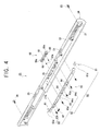
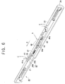
- a portable computer 1 comprises generally a main body 10 which outputs a video signal, and an LCD assembly 50, which displays the video signal received from the main body 10.
- the LCD assembly 50 has a free end 50a and is rotatably connected to the main body 10 at a hinged end 50b of the LCD assembly.
- the main body 10 comprises a main board (not shown) mounted inside the main body 10.
- the main board is provided with a CPU (central processing unit), a RAM (random access memory), and other conventional components of a portable computer.
- An input unit comprising a keyboard 13 and a touch pad 11 are provided on the main body 10.
- a rear part of the main body 10 is provided with a pair of hinge parts 15, which co-operate with hinge pins 16 to rotatably connect the main body 10 to the LCD assembly 50.
- a front portion of the main body 10 is covered by a front cover 20.
- the front cover 20 is secured to the front of the main body 10 using fasteners, such as for example, screws 26.
- the hinge parts 15 each have an annular hollow structure. They are provided in rear opposite sides of the main body 10, making a pair., The hinge parts 15 protrude upwardly from a surface of the main body 10. Each hinge part 15 accommodates a hinge pin 16 within its annulus. Each hinge pin 16 is inserted into a corresponding hinge pin holder 57 of the LCD assembly 20, thereby allowing the LCD assembly 20 to rotate with respect to the main body 10, the front part 50a being able to rotate away from the front of main body 10.
- the front cover 20 which is preferably made of a plastic material, is in the shape of elongate bar.
- the front cover 20 is fastened to the front of the main body 10 with the screws 26, thereby covering the front of the main body 10.
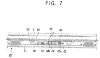
- An inside wall 21 of the front cover 20 is provided with a movable hook holding part (latch hook receptacle) 62 which is a part of a latch apparatus 60 described in more detail below.
- the front cover 20 is provided a pair of hook through-holes 23 in register with a pair of fixed hooks 61 of the latch apparatus 60, so as to allow the fixed hooks 61 to pass through the hook through holes 23 as the front cover 20 meets the free end 50a of the LCD assembly 50.
- the fixed hooks 61 are mounted on the free end 50a of the LCD assembly 50.
- a plurality of holes 25 are provided in a front part 24 of the front cover 20 through which a knob part 66 (further described below) connects with the front cover 20.
- the knob part 66 is exposed to be accessible from outside the portable computer 1 when the LCD assembly 50 is closed onto the main body 10.
- An audio part 30 is provided on a front centre edge of the main body 10.
- the audio part 30 is exposed to the outside of the portable computer 1 through a cutaway 56 formed in a front centre edge of the LCD assembly 50 when the LCD assembly 50 is locked onto the main body 10 by the latch apparatus 60.
- the audio part 30 comprises an LCD 31 for displaying characters, and a plurality of control buttons 32.
- the audio part 30 is controllable to reproduce sound, such as music, by operation of the control buttons 32 exposed through the aperture 56 of the LCD assembly 50 when the LCD assembly 50 is locked onto the main body 10 by the latch apparatus 60.
- the LCD assembly 50 includes an LCD casing 51, an LCD panel 53 accommodated in the LCD casing 51, and a backlight unit (not shown) installed in the back of the LCD panel 53.
- the LCD panel 53 receives a video signal from the main body 10 through an LCD-FPC (flexible PIC concentrator) (not shown) and displays a picture accordingly.
- the backlight unit transmits plane light to the LCD panel 53 and illuminates the picture displayed on the LCD panel 53 for viewing by a user.
- the aperture 56 has a predetermined area so as to expose the whole of the audio part 30, even where the LCD assembly 50 is locked onto the main body 10 by the latch apparatus 60.
- the hinge pins 16 are inserted into their corresponding hinge pin holder 57.
- each hinge pin holder 57 is rotatably connected to each hinge part 15 by the hinge pin 16, thereby allowing the LCD assembly 50 to rotate in relation to the main body 10 as shown in Figures 2 and 3.
- the latch apparatus 60 is shown comprising the pair of fixed hooks 61.
- the movable hook part 62 is provided in the front cover 20 of the main body 10, and is movable between a locking position, in which the movable hook part is hooked to the fixed hooks 61, and a release position, in which the movable hook part 62 is released from the fixed hooks 61. Movement of the knob part 66 causes the knob part 66 to move the movable hook part 62 to the release position.
- the pair of fixed hooks 61 may be collectively referred to as a support hook part.
- the fixed hooks 61 protrude one on each side of a central point of the front cover 20 and adjacent to the aperture 56 of the LCD assembly 50.
- the fixed hooks travel downwards towards the main body 10 as the LCD assembly 50 closes onto the main body 10.
- Each fixed hook 61 has a hook end 61a.
- the fixed hooks 61 can be hooked to the movable hook part 62 after passing through the hook through-holes 23, and can be released from the movable hook part 62 by translation thereof, so as to allow the LCD assembly 50 to be opened away from the main body 10.
- the movable hook part 62 is made of a durable material, such as for example, steel, and, as clearly shown in Figures 4 and 5, includes a movable hook 63 at each end.
- the hooks 63 are positioned beneath the hook through-holes 23 in register with the fixed hooks 61.
- the movable hook part 62 has through-holes 64, through which guiding parts 69a of the knob part 66 (further described below) pass, and has a contact parts 64a protruding inwardly in their respective through-hole 64 which contact with the guiding part 69a so as to guide it.
- the movable hook part 62 comprises a bolt through hole 65 by which the movable hook part 62 is connected to the inside wall 21 of the front cover 20 with a bolt 65a.
- the movable hook part 62 has a plurality of bolt through holes 65 through which a plurality of bolts 65a pass to connect the moveable hook part 62 to the front cover 21.
- the movable hooks 63 are provided at opposite ends of the movable hook part 62.
- Each movable hook 63 includes a hook holder 63b which is lockable to and releasable from the hook end 61a of the corresponding fixed hook 61, and an inclined part 63a inclined toward the hook 61a for guiding the corresponding fixed hook 61.
- the bolt through holes 65 are formed in the movable hook part 62 to permit movement of the movable hook part 62 in a lengthwise direction of the movable hook part 62 relative to the front part 24, and to restrict movement of the hook part 62 in other directions.
- the bolts 65a when inserted into the bolt through holes 65, connect the movable hook part 62 to screw bosses 21a on the inside wall 21 of the front cover 20.
- the bolt through holes 65 and the bolts 65a allow the movable hook part 62 to move between the releasing position and the locking position.
- the knob part 66 is made of a suitable material, such as a plastic material, and comprises a push button part 68 connected to the front cover 20 on the outside thereof. Projection parts 69 extend from the push button part 68 into the through holes 64 of the movable hook part 62. An elastic member 67 is connected between the movable hook part 62 and the front part 24 to return the movable hook part 62 and the knob part 66 to a predetermined position after operation of the latch apparatus.
- the push button part 68 is connected to the holes 25 of the front cover 20 and movable in a direction indicated by the arrow A when pressed by a user.
- Springs 20a aid in returning the push button part 68 to a predetermined position where the push button part 68 is not being pressed.
- the springs 20a are held captive between the push button part 68 and the front part 24.
- Each projection part 69 extends from the push button part 68 into a respective through hole 64 of the movable hook part 62.
- the guiding parts 69a are provided on rear parts of their respective projection part 69, and guide the movable hook part 62 from the locking position to the release position by contacting with contact parts 64a of the through holes 64 when the push button part 68.
- a first end of the elastic member 67 is coupled to the movable hook part 62, and a second end is coupled to the front cover 20 to restore the movable hook part 62 to a predetermined position when a pressing force acting on the push button part 68 is removed.
- the pair of movable hooks 63 each positioned under a respective one of the hook through holes 23 and cooperating with a respective one of the contact parts 64a are moved from a retaining position ( Figure 7) to the releasing position ( Figure 8), so that the movable hooks 63 are released from their respective hook 61a ( Figure 9).
- a user rotates a front part 50a of the LCD assembly 50 upwardly away from the main body 10 in a direction indicated by arrows C , releasing the fixed hooks 61 ( Figure 9), thereby opening up the portable computer 1, as shown in Figure 3.
- a process of locking the LCD assembly 50 onto the main body 10 follows.
- a user rotates the LCD assembly 50 downwardly against the main body 10,causing the fixed hooks 61 to be inserted into their respective hook through-hole 23.
- the fixed hooks 61 press respective inclined parts 63a of the movable hook part 62 ( Figure 10), so that the movable hook part 62 is moved toward the release position as the inclined part 63a is pushed out ( Figure 11).
- the LCD assembly 50 is provided with the fixed hooks 61 to be hooked to and released from the movable hooks 63 of the main body 10.
- the main body 10 is provided with the movable hook part 62 and the knob part 66, which are employed as the latch apparatus 60, thereby providing a portable computer having latch apparatus which is convenient to handle.
- the audio open part 56 may be provided in the LCD assembly 50, which enables some functions of the main body 10 (particularly, the audio part 30) to be controlled even where the LCD assembly 50 is locked onto the main body 10 ( Figure 2).
- a second embodiment of the portable computer 1 of the present invention incorporates an LCD opening unit 70 as shown in Figure 13.
- the LCD opening unit 70 enables an operator to open/close the portable computer 1 with one hand.
- the opening unit 70 replaces the hinge pins 16, shown in Figure 3.
- the LCD opening unit 70 comprises a first supporting part 71 removably combined to the main body 10, a second supporting part 75 removably connected to the LCD assembly 50, a rotation supporting part 80 having a hinge shaft 81 extended from the second supporting part 75 and a hinge shaft accommodating part 83 which receives the hinge shaft 81 so as to allow rotation, and a torsion spring 85 coiled around the hinge shaft 81 and having first and second ends which engage the first and second supporting parts 71 and 75, respectively.
- the first supporting part 71 is made of a durable material, such as steel, and comprises a main part 72 including the hinge shaft accommodating part 83, a flange part 73 protruding from the main part 72 a direction in parallel with an upper surface 17a of the main body 10, and having a coupling hole 73a therein for screw-coupling the first supporting part 71 to the main body 10, and an extended part 74 extended downwardly from the main part 72 and formed with a screw receptacle 74a therein.
- a durable material such as steel
- the main part 72 is connected to the hinge part 15, has an inverted "U" shape cross-section, and has a bottom surface with contacts with the surface 17a.
- the first supporting part 71 is fastened to the main body 10 by inserting a screw (not shown) through the coupling hole 73a into a screw hole 17b formed on the surface 17a of the main body 10 and by inserting a screw (not shown) into the screw receptacle 74a of the extended part 74 from inside of the main body 10 through a screw hole 17c.
- a stopper or lip 72a which prevents a first end 85a of the torsion spring 85 is from a breaking away when the latch apparatus 60 is locked.
- the second supporting part 75 is also made of a durable material, such as for example, steel.
- the second supporting part 75 comprises: a shaft part 76 which receives the hinge shaft 81: and a bracket part 77 extending from the shaft part 76 and having a plurality of coupling holes 77a for screw-coupling the second supporting part to the LCD assembly 50 using screws (not shown) and screw holes 58 formed in the LCD assembly 50.
- the end of the hinge shaft 81 opposite the shaft part 76 is fitted into the hinge shaft accommodating part 83 so as to connect the second supporting part 75 with the first supporting part 71.
- the hinge shaft 81 is forcibly fitted into one of the first supporting part 71 and the second supporting part 75 so that it can rotate onto one of those parts. That is, the hinge shaft 81 may be forcibly fitted to the shaft accommodating part 83 , with rotation being allowed in the shaft part 76. Alternatively, the hinge shaft 81 may be forcibly fitted to the shaft part 76, being allowed.
- a suspending member such as for example a screw 78, is removably connected onto the shaft part 76 so as to suspend the second end 85b of the torsion spring 85.
- the torsion spring 85 has its second end 85b suspended on the suspending member 78 of the second supporting part 75, and its first end 85a suspended on the stopper or lip 72a of the first supporting part 71.
- the spring 85 exerts a torque or force on the second supporting part 75 when the latch apparatus 60 is in the locking position, so that the second supporting part 75 is elastically rotated relative to the first supporting part 71 from a first position as shown in Figure 16B to a second position as shown in Figure 16A, thus forcing the LCD assembly 50 to move from a closed position to an open position.
- the first and second supporting parts 71 and 75 of the LCD opening unit 70 are relatively positioned as shown in Figure. 16B when the LCD assembly 50 is locked onto the main body 10, that is when the computer 1 is closed
- the torsion spring 85 of the LCD opening unit 70 is wound so as to provide a restoring force or torque while the fixed hooks 61 are engaged with the movable hook part 62.
- the latch apparatus 60 is released, the torsion spring 85 rotates the second supporting part 75 relative to the first supporting part 71 to the open position of the LCD assembly 50 by the restoring force of the wound torsion spring 85. Therefore, the LCD assembly 50 coupled to the second supporting part 75 is automatically opened away from the main body 10, from the locking position shown in Figure 2 to the open position shown in Figure 13. Consequently, the portable computer 1 is openable, and closable, by an operator using one hand.
- the first supporting part 71 is provided with the hinge shaft accommodating part 83, and the second supporting part 75 is provided with the hinge shaft 81.
- the first supporting part may be provided with the hinge shaft part, and the second supporting part may be provided with the hinge shaft accommodating part.
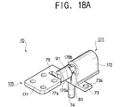
- the LCD opening unit 70 is constructed as shown in FIGS. 17, 18A and 18B.
- a stopper 91 is provided to restrict the maximum extent of a rotation of a shaft part 176a.
- a contact part 176b is provided in one side of the shaft part 176a. The contact part 176b is positioned to contact the stopper 91 of the first supporting part 171 when the LCD assembly 50 is locked to or released from the main body 10 in either direction of rotation.
- the LCD assembly 50 is rotated toward the main body 10 as shown in Figure 18B
- the maximum extent of rotation of the shaft part 176a is restricted by the stopper 91 and the contact part 176b. Therefore, where the LCD assembly 50 is rotated toward the main body 10, the LCD assembly 50 maintains a predetermined angle ⁇ with a surface 10a of the main body 10.
- the surface 10 is indicated by dashed lines in Figure 18B.
- the stopper 91 of the first supporting part 171 keeps the bracket part 177 of the second supporting part 175 at the predetermined angle ⁇ with the main body 10, not in parallel with the surface of the main body 10, so that the portable computer 1 is not completely closed.
- the neck part 79 which connects the bracket part 177 with the shaft part 176a has a predetermined width and operates as a flat spring.
- the neck part 79 of the second supporting part 175 is returned to the original position by its elasticity, causing the LCD assembly 50 to be opened to at least the predetermined angle ⁇ from the surface of the main body 10. That is, when the LCD assembly 50 is released from the main body 10 by the latch apparatus 60 when the contact part 176b formed in the shaft part 176a of the second supporting part 175 is contacting the stopper 91 of the first supporting part 171, the bracket part 177 is rotated from the locking or closed position toward the open position because of the restoring force provided by the neck part 79 of the second supporting part 175. Therefore, the LCD assembly 50 is rotated relative to the main body 10 from the locking or closed position toward the open position. Because the neck part 79 is employed as the flat spring, the LCD assembly 50 is automatically opened at a predetermined angle of at least ⁇ relative to the main body 10.
- the LCD opening unit 70 includes the first supporting part 71, the second supporting part 75, the rotation supporting part 80, and the torsion spring 85.
- the LCD opening unit 70 includes the first supporting part 171, the rotation supporting part 80 and the torsion neck (neck part) 79.
- a flat spring 93 has first and second ends 93a, 93b, each fastened to the main body 10, and a middle part 93c upwardly curved and selectively contactable with the LCD assembly 50.
- a flat spring 93 has first and second ends 93a, 93b, each fastened to the main body 10, and a middle part 93c upwardly curved and selectively contactable with the LCD assembly 50.
- a pair of compression springs 95 each have first and second ends, 95a, 95b, coupled one to the main body 10 and one to the LCD assembly 50, to aid in opening the portable computer 1.
- the embodiments provide a portable computer having a latch apparatus, which is convenient to operate, and a portable computer which is adapted to be opened/closed with one hand.
Landscapes
- Engineering & Computer Science (AREA)
- Computer Hardware Design (AREA)
- Theoretical Computer Science (AREA)
- General Engineering & Computer Science (AREA)
- Physics & Mathematics (AREA)
- Human Computer Interaction (AREA)
- General Physics & Mathematics (AREA)
- Mathematical Physics (AREA)
- Devices For Indicating Variable Information By Combining Individual Elements (AREA)
- Liquid Crystal (AREA)
Applications Claiming Priority (4)
| Application Number | Priority Date | Filing Date | Title |
|---|---|---|---|
| KR2002005681 | 2002-01-31 | ||
| KR20020005681 | 2002-01-31 | ||
| KR2002020267 | 2002-04-13 | ||
| KR10-2002-0020267A KR100461183B1 (ko) | 2002-01-31 | 2002-04-13 | 휴대용 컴퓨터 |
Publications (2)
| Publication Number | Publication Date |
|---|---|
| EP1351114A2 true EP1351114A2 (de) | 2003-10-08 |
| EP1351114A3 EP1351114A3 (de) | 2006-07-19 |
Family
ID=27615780
Family Applications (1)
| Application Number | Title | Priority Date | Filing Date |
|---|---|---|---|
| EP02255345A Withdrawn EP1351114A3 (de) | 2002-01-31 | 2002-07-31 | Tragbarer Rechner |
Country Status (4)
| Country | Link |
|---|---|
| US (1) | US6937465B2 (de) |
| EP (1) | EP1351114A3 (de) |
| JP (1) | JP3688665B2 (de) |
| CN (1) | CN1239976C (de) |
Families Citing this family (43)
| Publication number | Priority date | Publication date | Assignee | Title |
|---|---|---|---|---|
| JP2005070970A (ja) * | 2003-08-21 | 2005-03-17 | Toshiba Corp | 電子機器 |
| JP2005070969A (ja) * | 2003-08-21 | 2005-03-17 | Toshiba Corp | 電子機器および電子機器に用いる操作ユニット |
| KR100541737B1 (ko) * | 2003-10-09 | 2006-01-11 | 삼성전자주식회사 | 휴대용 컴퓨터 |
| CN100367152C (zh) * | 2004-05-20 | 2008-02-06 | 无敌科技股份有限公司 | 卡扣装置 |
| US20060002062A1 (en) * | 2004-07-02 | 2006-01-05 | Kwon Hae O | Latch device for portable computer |
| KR100727665B1 (ko) * | 2004-07-06 | 2007-06-13 | 엘지전자 주식회사 | 휴대용 컴퓨터의 래치장치 |
| JP4413230B2 (ja) * | 2004-08-19 | 2010-02-10 | 富士通株式会社 | ポインティングデバイスを有する電子機器 |
| US20060050474A1 (en) * | 2004-09-08 | 2006-03-09 | Hiroyuki Kusaka | Computer with restriction feature for restricting user access |
| US7405927B2 (en) * | 2004-09-10 | 2008-07-29 | Hewlett-Packard Development Company, L.P. | Push-button latching mechanism |
| JP4533712B2 (ja) * | 2004-09-30 | 2010-09-01 | 株式会社東芝 | 電子機器 |
| CN2763866Y (zh) * | 2004-11-24 | 2006-03-08 | 鸿富锦精密工业(深圳)有限公司 | 笔记本电脑上盖锁固装置 |
| CN2763868Y (zh) * | 2004-12-11 | 2006-03-08 | 鸿富锦精密工业(深圳)有限公司 | 笔记本电脑上盖锁固装置 |
| US20060133019A1 (en) * | 2004-12-21 | 2006-06-22 | Fuminori Yamazaki | Latch assembly for an electronic device |
| TWM268883U (en) * | 2004-12-24 | 2005-06-21 | Inventec Corp | Display of notebook computer |
| TWI266977B (en) * | 2004-12-30 | 2006-11-21 | Tatung Co Ltd | Common lock structure for dual portable computer |
| JP4647350B2 (ja) | 2005-03-08 | 2011-03-09 | 富士通株式会社 | 電子機器 |
| US7719826B1 (en) * | 2005-07-01 | 2010-05-18 | Apple Inc. | Integrated access cover |
| CN2849798Y (zh) * | 2005-11-15 | 2006-12-20 | 鸿富锦精密工业(深圳)有限公司 | 卡扣装置 |
| TWI299974B (en) * | 2006-03-01 | 2008-08-11 | Asustek Comp Inc | Electronic device with a sliding element |
| CN101193509B (zh) * | 2006-11-24 | 2010-04-14 | 鸿富锦精密工业(深圳)有限公司 | 卡钩装置及具有该装置的电子设备 |
| TWM314361U (en) * | 2007-01-19 | 2007-06-21 | Quanta Comp Inc | Latch design of a notebook computer |
| TW200900898A (en) * | 2007-06-21 | 2009-01-01 | Compal Electronics Inc | Latching mechanism and base casing of notebook using the same |
| JP5040532B2 (ja) * | 2007-08-31 | 2012-10-03 | 富士通株式会社 | 電子機器 |
| CN101441886A (zh) * | 2007-11-19 | 2009-05-27 | 鸿富锦精密工业(深圳)有限公司 | 碟片读取装置 |
| CN101446158B (zh) * | 2007-11-26 | 2010-12-08 | 康准电子科技(昆山)有限公司 | 卡扣装置 |
| US20090201639A1 (en) * | 2008-02-12 | 2009-08-13 | Inventec Corporation | Chassis of portable electronic apparatus |
| TWI338828B (en) * | 2008-07-09 | 2011-03-11 | Wistron Corp | Latch mechanism for latching a monitor and a host of a portable computer |
| US8270169B2 (en) * | 2009-03-24 | 2012-09-18 | Raytheon Company | Translating hinge |
| US8223293B2 (en) * | 2009-04-17 | 2012-07-17 | Compal Electronics, Inc. | Liquid crystal display and method of assembling liquid crystal display |
| CN101872212B (zh) * | 2009-04-23 | 2013-08-07 | 鸿富锦精密工业(深圳)有限公司 | 笔记本电脑及其连接装置 |
| US8988190B2 (en) * | 2009-09-03 | 2015-03-24 | Dell Products, Lp | Gesture based electronic latch for laptop computers |
| TWI418971B (zh) * | 2010-11-16 | 2013-12-11 | Inventec Corp | 筆記型電腦 |
| CN103429034A (zh) * | 2012-05-25 | 2013-12-04 | 鸿富锦精密工业(深圳)有限公司 | 具有扣合结构的电子装置 |
| TWI515531B (zh) * | 2012-09-04 | 2016-01-01 | 緯創資通股份有限公司 | 電腦設備 |
| CN103713693B (zh) * | 2012-09-28 | 2017-11-03 | 联想(北京)有限公司 | 一种电子设备 |
| TWI502322B (zh) * | 2013-05-23 | 2015-10-01 | Wistron Corp | 可攜式電子裝置 |
| WO2015152911A1 (en) * | 2014-04-02 | 2015-10-08 | Hewlett-Packard Development Company, L. P. | Hinge assembly including an elastomer member |
| CN110352396B (zh) * | 2017-02-24 | 2023-03-17 | 松下知识产权经营株式会社 | 电子设备 |
| JP1619447S (de) * | 2018-07-06 | 2018-12-03 | ||
| USD924872S1 (en) * | 2019-08-16 | 2021-07-13 | Samsung Electronics Co., Ltd. | Keyboard for electronic device |
| JP7521204B2 (ja) * | 2020-02-28 | 2024-07-24 | 京セラドキュメントソリューションズ株式会社 | カバー取り付け構造 |
| JP6923704B1 (ja) * | 2020-04-03 | 2021-08-25 | レノボ・シンガポール・プライベート・リミテッド | 筐体用部材、電子機器及び筐体用部材の製造方法 |
| TWI910929B (zh) * | 2024-11-26 | 2026-01-01 | 英業達股份有限公司 | 卡勾對搜尋配對方法 |
Family Cites Families (17)
| Publication number | Priority date | Publication date | Assignee | Title |
|---|---|---|---|---|
| CH564314A5 (de) | 1973-04-17 | 1975-07-31 | Nestle Sa | |
| JPS63167569A (ja) | 1986-12-29 | 1988-07-11 | Matsushita Electric Ind Co Ltd | 画像フアイル装置 |
| JPS6441575A (en) | 1987-08-07 | 1989-02-13 | Sharp Kk | Composite synchronizing signal analyzing circuit |
| NZ225652A (en) | 1988-08-02 | 1992-05-26 | Skellerup Rubber Mfg | Aseismic bearing: resilient discs fixed to stacked plates |
| JP2810960B2 (ja) | 1988-10-08 | 1998-10-15 | 加藤電機株式会社 | 開閉体の開閉用ヒンジ |
| US5173837A (en) | 1990-10-15 | 1992-12-22 | Compaq Computer Corporation | Hinge with two-towed clutch spring for suppressing electromagnetic interference for laptop personal computers |
| KR930001396A (ko) | 1991-06-18 | 1993-01-16 | 김광호 | 금속 배선 제조 방법 |
| JP3142151B2 (ja) | 1991-07-05 | 2001-03-07 | 株式会社ノーケン | 振動式レベル検出装置 |
| JPH0738505B2 (ja) * | 1992-10-12 | 1995-04-26 | インターナショナル・ビジネス・マシーンズ・コーポレイション | 蓋付き構造体、及び、情報処理装置 |
| JP3425186B2 (ja) | 1993-06-22 | 2003-07-07 | 株式会社東芝 | 画像診断装置 |
| JP2500099B2 (ja) * | 1993-07-22 | 1996-05-29 | インターナショナル・ビジネス・マシーンズ・コーポレイション | 蓋付き構造体 |
| US5715575A (en) * | 1995-03-13 | 1998-02-10 | Kato Spring Works Co., Ltd. | Hinge device |
| JP3669758B2 (ja) * | 1995-06-15 | 2005-07-13 | ユニ・チャーム株式会社 | 蓋装置 |
| US5580107A (en) | 1995-09-25 | 1996-12-03 | Dell U.S.A., L.P. | Hidden latch hook for portable personal computer and the like |
| JPH09292936A (ja) * | 1996-02-29 | 1997-11-11 | Toshiba Corp | ポータブルコンピュータ |
| KR200158700Y1 (ko) * | 1997-03-15 | 1999-10-15 | 윤종용 | 잠금장치와 잠금장치가 설치된 휴대용 컴퓨터 |
| US6659516B2 (en) * | 2001-01-05 | 2003-12-09 | Apple Computer, Inc. | Locking system for a portable computer |
-
2002
- 2002-07-10 US US10/191,405 patent/US6937465B2/en not_active Expired - Lifetime
- 2002-07-30 JP JP2002221460A patent/JP3688665B2/ja not_active Expired - Fee Related
- 2002-07-31 CN CNB021273103A patent/CN1239976C/zh not_active Expired - Fee Related
- 2002-07-31 EP EP02255345A patent/EP1351114A3/de not_active Withdrawn
Also Published As
| Publication number | Publication date |
|---|---|
| JP2003241854A (ja) | 2003-08-29 |
| JP3688665B2 (ja) | 2005-08-31 |
| US20030142472A1 (en) | 2003-07-31 |
| CN1435741A (zh) | 2003-08-13 |
| EP1351114A3 (de) | 2006-07-19 |
| US6937465B2 (en) | 2005-08-30 |
| CN1239976C (zh) | 2006-02-01 |
Similar Documents
| Publication | Publication Date | Title |
|---|---|---|
| EP1351114A2 (de) | Tragbarer Rechner | |
| US5465191A (en) | Single hand operable latch mechanism for hinged container | |
| US5635928A (en) | Data processing device with a keyboard having pop-up keys | |
| US6867961B2 (en) | Portable computer | |
| EP1380920B1 (de) | Funktionserweiterungsvorrichtung für Informationsverarbeitungsgerät | |
| US6912121B2 (en) | Personal computer device having constant tilt display with adjustable height | |
| US6778196B2 (en) | Mounting a display panel in a computer | |
| US5209448A (en) | Flat display holding mechanism | |
| GB2228357A (en) | Flat display supporting mechanism | |
| US6654068B1 (en) | Brake mechanism for controlling the tilt of a computer display | |
| CN203675146U (zh) | 便携式电子设备 | |
| US5068498A (en) | Joystick for mounting on dual-width panels | |
| JP2001050244A (ja) | ユニット回動支持機構 | |
| JPH08262993A (ja) | 携帯型情報処理装置及び携帯型情報処理装置用スタンド | |
| JP4545382B2 (ja) | 遊技機枠 | |
| JPH06310875A (ja) | ヒンジ装置 | |
| US20060274492A1 (en) | Portable computer having a keyboard coupled to a computer main body | |
| KR20030065257A (ko) | 휴대용 컴퓨터 | |
| JP2949538B2 (ja) | ノート型コンピュータ装置 | |
| JP2003339428A (ja) | コンパクト容器 | |
| JP2003334359A (ja) | 遊技機用のヒンジ | |
| US20040252450A1 (en) | Computer mainframe | |
| KR100549082B1 (ko) | 휴대용 컴퓨터 | |
| JPH0934370A (ja) | 上下反転表示が可能な携帯型情報処理装置 | |
| JPH07325644A (ja) | 表示装置を備えた電子機器 |
Legal Events
| Date | Code | Title | Description |
|---|---|---|---|
| PUAI | Public reference made under article 153(3) epc to a published international application that has entered the european phase |
Free format text: ORIGINAL CODE: 0009012 |
|
| AK | Designated contracting states |
Kind code of ref document: A2 Designated state(s): AT BE BG CH CY CZ DE DK EE ES FI FR GB GR IE IT LI LU MC NL PT SE SK TR |
|
| AX | Request for extension of the european patent |
Extension state: AL LT LV MK RO SI |
|
| RAP1 | Party data changed (applicant data changed or rights of an application transferred) |
Owner name: SAMSUNG ELECTRONICS CO., LTD. |
|
| PUAL | Search report despatched |
Free format text: ORIGINAL CODE: 0009013 |
|
| AK | Designated contracting states |
Kind code of ref document: A3 Designated state(s): AT BE BG CH CY CZ DE DK EE ES FI FR GB GR IE IT LI LU MC NL PT SE SK TR |
|
| AX | Request for extension of the european patent |
Extension state: AL LT LV MK RO SI |
|
| AKX | Designation fees paid | ||
| 17P | Request for examination filed |
Effective date: 20070109 |
|
| RBV | Designated contracting states (corrected) |
Designated state(s): AT BE BG CH LI |
|
| RBV | Designated contracting states (corrected) |
Designated state(s): DE FR GB NL |
|
| REG | Reference to a national code |
Ref country code: DE Ref legal event code: 8566 |
|
| 17Q | First examination report despatched |
Effective date: 20071123 |
|
| RAP1 | Party data changed (applicant data changed or rights of an application transferred) |
Owner name: SAMSUNG ELECTRONICS CO., LTD. |
|
| STAA | Information on the status of an ep patent application or granted ep patent |
Free format text: STATUS: EXAMINATION IS IN PROGRESS |
|
| STAA | Information on the status of an ep patent application or granted ep patent |
Free format text: STATUS: THE APPLICATION IS DEEMED TO BE WITHDRAWN |
|
| 18D | Application deemed to be withdrawn |
Effective date: 20170201 |