EP1351330A2 - Brennstoffzelle und Verfahren zum Kaltstarten einer solchen Brennstoffzelle - Google Patents
Brennstoffzelle und Verfahren zum Kaltstarten einer solchen Brennstoffzelle Download PDFInfo
- Publication number
- EP1351330A2 EP1351330A2 EP03004709A EP03004709A EP1351330A2 EP 1351330 A2 EP1351330 A2 EP 1351330A2 EP 03004709 A EP03004709 A EP 03004709A EP 03004709 A EP03004709 A EP 03004709A EP 1351330 A2 EP1351330 A2 EP 1351330A2
- Authority
- EP
- European Patent Office
- Prior art keywords
- fuel cell
- coolant
- unit
- fuel
- cell according
- Prior art date
- Legal status (The legal status is an assumption and is not a legal conclusion. Google has not performed a legal analysis and makes no representation as to the accuracy of the status listed.)
- Withdrawn
Links
Images


Classifications
-
- H—ELECTRICITY
- H01—ELECTRIC ELEMENTS
- H01M—PROCESSES OR MEANS, e.g. BATTERIES, FOR THE DIRECT CONVERSION OF CHEMICAL ENERGY INTO ELECTRICAL ENERGY
- H01M8/00—Fuel cells; Manufacture thereof
- H01M8/04—Auxiliary arrangements, e.g. for control of pressure or for circulation of fluids
- H01M8/04007—Auxiliary arrangements, e.g. for control of pressure or for circulation of fluids related to heat exchange
- H01M8/04067—Heat exchange or temperature measuring elements, thermal insulation, e.g. heat pipes, heat pumps, fins
-
- C—CHEMISTRY; METALLURGY
- C01—INORGANIC CHEMISTRY
- C01B—NON-METALLIC ELEMENTS; COMPOUNDS THEREOF; METALLOIDS OR COMPOUNDS THEREOF NOT COVERED BY SUBCLASS C01C
- C01B3/00—Hydrogen; Gaseous mixtures containing hydrogen; Separation of hydrogen from mixtures containing it; Purification of hydrogen; Reversible storage of hydrogen
- C01B3/0005—Reversible storage of hydrogen, e.g. by hydrogen getters or electrodes
- C01B3/001—Reversible storage of hydrogen, e.g. by hydrogen getters or electrodes characterised by the uptaking media; Treatment thereof
- C01B3/0018—Inorganic elements or compounds, e.g. oxides, nitrides, borohydrides or zeolites; Solutions thereof
- C01B3/0031—Intermetallic compounds; Metal alloys
- C01B3/0036—Intermetallic compounds; Metal alloys only containing iron and titanium
-
- C—CHEMISTRY; METALLURGY
- C01—INORGANIC CHEMISTRY
- C01B—NON-METALLIC ELEMENTS; COMPOUNDS THEREOF; METALLOIDS OR COMPOUNDS THEREOF NOT COVERED BY SUBCLASS C01C
- C01B6/00—Hydrides of metals including fully or partially hydrided metals, alloys or intermetallic compounds ; Compounds containing at least one metal-hydrogen bond, e.g. (GeH3)2S, SiH GeH; Monoborane or diborane; Addition complexes thereof
- C01B6/24—Hydrides containing at least two metals; Addition complexes thereof
-
- H—ELECTRICITY
- H01—ELECTRIC ELEMENTS
- H01M—PROCESSES OR MEANS, e.g. BATTERIES, FOR THE DIRECT CONVERSION OF CHEMICAL ENERGY INTO ELECTRICAL ENERGY
- H01M4/00—Electrodes
- H01M4/86—Inert electrodes with catalytic activity, e.g. for fuel cells
- H01M4/90—Selection of catalytic material
- H01M4/92—Metals of platinum group
-
- H—ELECTRICITY
- H01—ELECTRIC ELEMENTS
- H01M—PROCESSES OR MEANS, e.g. BATTERIES, FOR THE DIRECT CONVERSION OF CHEMICAL ENERGY INTO ELECTRICAL ENERGY
- H01M8/00—Fuel cells; Manufacture thereof
- H01M8/02—Details
- H01M8/0202—Collectors; Separators, e.g. bipolar separators; Interconnectors
- H01M8/0267—Collectors; Separators, e.g. bipolar separators; Interconnectors having heating or cooling means, e.g. heaters or coolant flow channels
-
- H—ELECTRICITY
- H01—ELECTRIC ELEMENTS
- H01M—PROCESSES OR MEANS, e.g. BATTERIES, FOR THE DIRECT CONVERSION OF CHEMICAL ENERGY INTO ELECTRICAL ENERGY
- H01M8/00—Fuel cells; Manufacture thereof
- H01M8/04—Auxiliary arrangements, e.g. for control of pressure or for circulation of fluids
- H01M8/04007—Auxiliary arrangements, e.g. for control of pressure or for circulation of fluids related to heat exchange
- H01M8/04014—Heat exchange using gaseous fluids; Heat exchange by combustion of reactants
-
- H—ELECTRICITY
- H01—ELECTRIC ELEMENTS
- H01M—PROCESSES OR MEANS, e.g. BATTERIES, FOR THE DIRECT CONVERSION OF CHEMICAL ENERGY INTO ELECTRICAL ENERGY
- H01M8/00—Fuel cells; Manufacture thereof
- H01M8/04—Auxiliary arrangements, e.g. for control of pressure or for circulation of fluids
- H01M8/04082—Arrangements for control of reactant parameters, e.g. pressure or concentration
- H01M8/04201—Reactant storage and supply, e.g. means for feeding, pipes
- H01M8/04216—Reactant storage and supply, e.g. means for feeding, pipes characterised by the choice for a specific material, e.g. carbon, hydride, absorbent
-
- H—ELECTRICITY
- H01—ELECTRIC ELEMENTS
- H01M—PROCESSES OR MEANS, e.g. BATTERIES, FOR THE DIRECT CONVERSION OF CHEMICAL ENERGY INTO ELECTRICAL ENERGY
- H01M8/00—Fuel cells; Manufacture thereof
- H01M8/04—Auxiliary arrangements, e.g. for control of pressure or for circulation of fluids
- H01M8/04223—Auxiliary arrangements, e.g. for control of pressure or for circulation of fluids during start-up or shut-down; Depolarisation or activation, e.g. purging; Means for short-circuiting defective fuel cells
- H01M8/04225—Auxiliary arrangements, e.g. for control of pressure or for circulation of fluids during start-up or shut-down; Depolarisation or activation, e.g. purging; Means for short-circuiting defective fuel cells during start-up
-
- H—ELECTRICITY
- H01—ELECTRIC ELEMENTS
- H01M—PROCESSES OR MEANS, e.g. BATTERIES, FOR THE DIRECT CONVERSION OF CHEMICAL ENERGY INTO ELECTRICAL ENERGY
- H01M8/00—Fuel cells; Manufacture thereof
- H01M8/04—Auxiliary arrangements, e.g. for control of pressure or for circulation of fluids
- H01M8/04223—Auxiliary arrangements, e.g. for control of pressure or for circulation of fluids during start-up or shut-down; Depolarisation or activation, e.g. purging; Means for short-circuiting defective fuel cells
- H01M8/04268—Heating of fuel cells during the start-up of the fuel cells
-
- H—ELECTRICITY
- H01—ELECTRIC ELEMENTS
- H01M—PROCESSES OR MEANS, e.g. BATTERIES, FOR THE DIRECT CONVERSION OF CHEMICAL ENERGY INTO ELECTRICAL ENERGY
- H01M8/00—Fuel cells; Manufacture thereof
- H01M8/04—Auxiliary arrangements, e.g. for control of pressure or for circulation of fluids
- H01M8/04298—Processes for controlling fuel cells or fuel cell systems
- H01M8/043—Processes for controlling fuel cells or fuel cell systems applied during specific periods
- H01M8/04302—Processes for controlling fuel cells or fuel cell systems applied during specific periods applied during start-up
-
- H—ELECTRICITY
- H01—ELECTRIC ELEMENTS
- H01M—PROCESSES OR MEANS, e.g. BATTERIES, FOR THE DIRECT CONVERSION OF CHEMICAL ENERGY INTO ELECTRICAL ENERGY
- H01M8/00—Fuel cells; Manufacture thereof
- H01M8/24—Grouping of fuel cells, e.g. stacking of fuel cells
- H01M8/241—Grouping of fuel cells, e.g. stacking of fuel cells with solid or matrix-supported electrolytes
-
- H—ELECTRICITY
- H01—ELECTRIC ELEMENTS
- H01M—PROCESSES OR MEANS, e.g. BATTERIES, FOR THE DIRECT CONVERSION OF CHEMICAL ENERGY INTO ELECTRICAL ENERGY
- H01M4/00—Electrodes
- H01M4/86—Inert electrodes with catalytic activity, e.g. for fuel cells
- H01M2004/8678—Inert electrodes with catalytic activity, e.g. for fuel cells characterised by the polarity
- H01M2004/8684—Negative electrodes
-
- H—ELECTRICITY
- H01—ELECTRIC ELEMENTS
- H01M—PROCESSES OR MEANS, e.g. BATTERIES, FOR THE DIRECT CONVERSION OF CHEMICAL ENERGY INTO ELECTRICAL ENERGY
- H01M8/00—Fuel cells; Manufacture thereof
- H01M8/04—Auxiliary arrangements, e.g. for control of pressure or for circulation of fluids
- H01M8/04007—Auxiliary arrangements, e.g. for control of pressure or for circulation of fluids related to heat exchange
- H01M8/04014—Heat exchange using gaseous fluids; Heat exchange by combustion of reactants
- H01M8/04022—Heating by combustion
-
- H—ELECTRICITY
- H01—ELECTRIC ELEMENTS
- H01M—PROCESSES OR MEANS, e.g. BATTERIES, FOR THE DIRECT CONVERSION OF CHEMICAL ENERGY INTO ELECTRICAL ENERGY
- H01M8/00—Fuel cells; Manufacture thereof
- H01M8/04—Auxiliary arrangements, e.g. for control of pressure or for circulation of fluids
- H01M8/04007—Auxiliary arrangements, e.g. for control of pressure or for circulation of fluids related to heat exchange
- H01M8/04029—Heat exchange using liquids
-
- Y—GENERAL TAGGING OF NEW TECHNOLOGICAL DEVELOPMENTS; GENERAL TAGGING OF CROSS-SECTIONAL TECHNOLOGIES SPANNING OVER SEVERAL SECTIONS OF THE IPC; TECHNICAL SUBJECTS COVERED BY FORMER USPC CROSS-REFERENCE ART COLLECTIONS [XRACs] AND DIGESTS
- Y02—TECHNOLOGIES OR APPLICATIONS FOR MITIGATION OR ADAPTATION AGAINST CLIMATE CHANGE
- Y02E—REDUCTION OF GREENHOUSE GAS [GHG] EMISSIONS, RELATED TO ENERGY GENERATION, TRANSMISSION OR DISTRIBUTION
- Y02E60/00—Enabling technologies; Technologies with a potential or indirect contribution to GHG emissions mitigation
- Y02E60/30—Hydrogen technology
- Y02E60/32—Hydrogen storage
-
- Y—GENERAL TAGGING OF NEW TECHNOLOGICAL DEVELOPMENTS; GENERAL TAGGING OF CROSS-SECTIONAL TECHNOLOGIES SPANNING OVER SEVERAL SECTIONS OF THE IPC; TECHNICAL SUBJECTS COVERED BY FORMER USPC CROSS-REFERENCE ART COLLECTIONS [XRACs] AND DIGESTS
- Y02—TECHNOLOGIES OR APPLICATIONS FOR MITIGATION OR ADAPTATION AGAINST CLIMATE CHANGE
- Y02E—REDUCTION OF GREENHOUSE GAS [GHG] EMISSIONS, RELATED TO ENERGY GENERATION, TRANSMISSION OR DISTRIBUTION
- Y02E60/00—Enabling technologies; Technologies with a potential or indirect contribution to GHG emissions mitigation
- Y02E60/30—Hydrogen technology
- Y02E60/50—Fuel cells
-
- Y—GENERAL TAGGING OF NEW TECHNOLOGICAL DEVELOPMENTS; GENERAL TAGGING OF CROSS-SECTIONAL TECHNOLOGIES SPANNING OVER SEVERAL SECTIONS OF THE IPC; TECHNICAL SUBJECTS COVERED BY FORMER USPC CROSS-REFERENCE ART COLLECTIONS [XRACs] AND DIGESTS
- Y02—TECHNOLOGIES OR APPLICATIONS FOR MITIGATION OR ADAPTATION AGAINST CLIMATE CHANGE
- Y02P—CLIMATE CHANGE MITIGATION TECHNOLOGIES IN THE PRODUCTION OR PROCESSING OF GOODS
- Y02P70/00—Climate change mitigation technologies in the production process for final industrial or consumer products
- Y02P70/50—Manufacturing or production processes characterised by the final manufactured product
Definitions
- the invention relates to a fuel cell with an electrolyte-electrode unit, on the one hand the cathode and on the other hand the anode of the fuel cell is arranged, and with flow modules arranged above these two electrodes for the process gases and the coolant of the fuel cell.
- the invention relates to a method for cold starting such a fuel cell.
- the ion exchange membrane comprises a sulfonated chemical compound which Water in the membrane binds to a sufficient proton conductivity to ensure. Due to the freezing of the water stored in the membrane increases the membrane resistance at a temperature below 0 ° C abruptly by two to three orders of magnitude. Even with low and medium temperature fuel cells, such as. the PAFC (Phosphoric Acid Fuel Cell), the resistance of the electrolyte increases at low Temperatures many times over. In addition to the electrochemical Properties of the electrolyte are usually also the activities the cathode and anode catalysts of a fuel cell temperature dependent. For PEM fuel cells, the To be pursued with reformat, is added that Reformat in the cold start phase very high carbon monoxide (CO) concentrations and the CO tolerance of the still cold fuel cell is extremely low.
- CO carbon monoxide
- the fuel cells known from practice therefore only starting from a certain starting temperature, which at present at about 5 ° C, produce electricity.
- For a cold start must a fuel cell so initially to temperatures above the starting temperature to be heated. Due to the large thermal Mass of fuel cells is a considerable Heating power required, especially if the cold start in similar to short times, as in conventional Internal combustion engines.
- a heating of the electrolyte-electrode unit regardless of the flow modules is not possible because the heat conduction between the electrolyte-electrode unit and the flow modules by design very much good at fuel cell operation the electrolyte-electrode unit resulting waste heat to the Dissipate environment.
- the following example should be the order of magnitude of the supplied Clarify heating power.
- a BZ stack i. a fuel cell unit consisting of several interconnected fuel cells, like them for example, is used for a car drive, should a generate maximum power of 60 kWel.
- Located in the BZ stack a further 5 kg of coolant, e.g.
- a water / glycol mixture with a heat capacity of 3 kJ / kg • K increases the required amount of heat to 750 kJ and the required heating power to 75 kW. Accordingly, the necessary increases Heating power at lower temperatures and, if shorter start times should be achieved.
- this is or is via the anode and / or the flow module disposed above the cathode at least partially formed from a material that can form a hydride, whereby heat is given off.
- trained fuel cell is or will be that over the anode and / or over the cathode Flow module flooded with a hydrogen-containing gas, so that hydride formation occurs. By doing so Heat is the fuel cell heated.
- the process gas channels of the anode side and / or cathode-side flow module at least partially with the hydride-forming material are coated.
- the low-temperature hydrides can form, such. Titanium-iron alloys (TiFe).
- Cryogenic hydrides can be hydrogen in a temperature range store from -30 ° C to + 50 ° C. It can pro kg of formed metal hydride 360 kJ heat energy are discharged. To generate 750 kJ thermal energy, as in the above described example, so need about 2.5 kg of metal hydride be formed.
- Another advantage of using Cryogenic hydrides is that the stored Hydrogen in the normal operating conditions of the fuel cell, Operating temperature T> 70 ° C and pressures lower 10bar, is released again.
- the invention discussed above can be Measures for heating a fuel cell during Cold start well with other heating measures combine, even if These are based on a different heating principle. Below are some advantageous combinations as developments of the invention explained in more detail.
- the inventive internal heating by exothermic hydride formation a suitable material in the range of at least one Flow module of the fuel cell works well with a combine further internal heating method, in the hydrogen is catalytically oxidized. By being released Energy is the fuel cell additionally heated. at this variant is in at least one of the flow modules of Fuel cell formed at least one reaction space in the in the cold start phase, both a hydrogen-containing fluid as Also, an oxygen-containing fluid can be introduced. In addition, there is an oxidation catalyst in this reaction space for the exothermic conversion of hydrogen, so that the reaction space acts like a catalytic burner.
- the oxidation reaction can be in an advantageous Way through an applied to this electrode oxidation catalyst be catalyzed.
- a special oxidation catalyst preferably low temperature should be active on the wall of the reaction space, So applied the surface of the flow module his.
- the oxidation reaction for example, by a ultrathin platinum layer catalyzed by PVC, CVD or also produced galvanically on the surface of the flow module has been.
- a platinum layer can simultaneously serve as corrosion protection for the flow module or possibly also ensure sufficient electrical conductivity.
- the inventive internal heating of the fuel cell by exothermic hydride formation of a suitable material in the range can also be powered by electrical heating the flow modules are supported, which is the main part form the thermal mass of a fuel cell. In this context, it proves to be advantageous if in at least one of the flow modules at least one heating element is mechanically integrated.
- the amount of the coolant passed through the fuel cell and thus the total thermal mass to be heated Fuel cell is reduced and the fuel cell for so long operated with the minimum required amount of coolant until the start temperature is reached.
- the Fuel cell in addition to the internal according to the invention Heating indirectly heated.
- the coolant can be simple are pumped out of the cooling circuit of the fuel cell, whereby reduced the thermal mass of the fuel cell by almost 50% can be. In this case you need a reservoir be provided, in which collected the pumped coolant will return to it after reaching the BZ start temperature Feed in cooling circuit.
- the heatable with the fuel cell Coolant can also by shorting the Cooling circuit can be reduced.
- coolant depending on the ambient temperature to reduce.
- the coolant may, for example electrically by means of an additional battery or by heated chemical energy with the help of a fuel burner become.
- a heat exchanger be at least partially made of a material, preferably coated with such a material, the can form a hydride, releasing heat.
- the heat exchanger At cold start is the heat exchanger with a hydrogen-containing gas flooded. By hydride formation or thereby released Heat, the coolant located in the heat exchanger is heated.
- BZ stacks In practice, mostly so-called fuel cell (BZ) stacks used, i. Fuel cell units, which consist of several consist of interconnected fuel cells. BZ stacks usually work with energetic efficiencies from 40-70%. The energy lost in the form of heat energy which is discharged via the coolant. A suitable regulation assuming the coolant flow, a BZ stack heats up by this loss energy independently from its starting temperature to its normal operating temperature.
- a fuel cell unit with a segmented structure proposed using a startup unit comprises at least one fuel cell, as described above has been described as being according to the invention, and at least one further unit with further fuel cells.
- the starting unit should at cold start first the fuel cells of the starting unit to be activated. Because the starting unit compared to entire fuel cell unit a smaller thermal mass represents, the starting unit can relatively quickly to the required Starting temperature are brought. The loss energy the starting unit heats the coolant, at least after reaching it the starting temperature also by the other units the fuel cell unit is passed and this heated, so that these too are brought to starting temperature.
- Fig. 1 shows the schematic representation of a BZ refrigeration cycle with short circuit possibility.
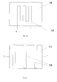
- FIGS. 2a and 2b show schematically the plan view, respectively on a equipped with electrical heating elements flow module.
- FIGS. 3a and 3b schematically show two interconnection options for the start unit of a fuel cell unit.
- fuel cells need in case of a Cold starts are first heated to their starting temperature, before they can generate power themselves.
- Fig. 1 clarifies, in this case only a fraction of the coolant quantity heated together with the fuel cell 1.
- the individual components anode 2, cathode 3 and cooling 4 of Fuel cell 1 are shown here only schematically.
- the cooling circuit 6 connected to a vehicle cooler 5 becomes shorted here via a simple thermostatic valve 7.
- the structure of a fuel cell and, accordingly, the Construction of a BZ stack essentially comprises one or more MEAs (Membrane Electrode Assemblies) and flow modules, which are mostly realized in the form of bipolar plates and a form a large part of the thermal mass of the structure.
- MEAs Membrane Electrode Assemblies
- FIGS. 2a and 2b each show a bipolar plate 10 and 11, in the electric heating elements 12 and 13 for heating the bipolar plate 10 and 11 and thereby the entire structure the fuel cell or the BZ stack are integrated.
- Fig. 2b are in the bipolar plate 11 regions 13 integrated with increased ohmic resistance, which serves as a heating conductor serve.
- the BZ stack depending on tolerable minimum power, in a start unit and more Segment units. If the BZ stack, for example, in Segmented ratio 1/3, so is the electrical power the startup unit only a quarter of the maximum power of the BZ stack. However, the mass of the starting unit is only a quarter of the BZ stack total mass, leaving the start unit be heated four times faster at a given heat output can be considered the entire BZ stack or at the same start time only a quarter of the heating power is required.
Landscapes
- Chemical & Material Sciences (AREA)
- Engineering & Computer Science (AREA)
- Chemical Kinetics & Catalysis (AREA)
- General Chemical & Material Sciences (AREA)
- Electrochemistry (AREA)
- Sustainable Development (AREA)
- Sustainable Energy (AREA)
- Life Sciences & Earth Sciences (AREA)
- Manufacturing & Machinery (AREA)
- Organic Chemistry (AREA)
- Combustion & Propulsion (AREA)
- Inorganic Chemistry (AREA)
- Materials Engineering (AREA)
- Fuel Cell (AREA)
Abstract
Description
- 1
- Brennstoffzelle (Fig. 1)
- 2
- Anode
- 3
- Kathode
- 4
- Kühlung
- 5
- Fahrzeugkühler
- 6
- Kühlkreislauf
- 7
- Thermostatventil
- 10
- Bipolarplatte (Fig. 2a)
- 11
- Bipolarplatte (Fig. 2b)
- 12
- Heizelement / Heizleiter
- 13
- Heizelement / Bereich mit erhöhtem Ohmschen Widerstand
- 20
- Starteinheit (Fig. 3a)
- 21
- Starteinheit (Fig. 3b)
Claims (28)
- Brennstoffzelledadurch gekennzeichnet, dass das über der Anode und/oder das über der Kathode angeordnete Strömungsmodul zumindest teilweise aus einem Material gebildet sind/ist, das ein Hydrid bilden kann, wobei Wärme abgegeben wird.mit einer Elektrolyt-Elektroden-Einheit, auf der einerseits die Kathode und andererseits die Anode der Brennstoffzelle angeordnet ist, undmit über diesen beiden Elektroden angeordneten Strömungsmodulen für die Prozessgase und das Kühlmittel der Brennstoffzelle,
- Brennstoffzelle nach Anspruch 1, dadurch gekennzeichnet, dass die Prozessgaskanäle des anodenseitigen und/oder kathodenseitigen Strömungsmoduls zumindest teilweise mit dem zur Hydridbildung fähigen Material beschichtet sind.
- Brennstoffzelle nach einem der Ansprüche 1 oder 2, dadurch gekennzeichnet, dass mindestens ein Metall oder eine Metalllegierung, das bzw. die Tieftemperaturhydride bilden kann, als zur Hydridbildung fähiges Material dient.
- Brennstoffzelle nach einem der Ansprüche 1 bis 3, dadurch gekennzeichnet, dass eine Titan-Eisenlegierung (TiFe) als zur Hydridbildung fähiges Material dient
- Brennstoffzelle nach einem der Ansprüche 1 bis 4, dadurch gekennzeichnet, dass in mindestens einem der Strömungsmodule mindestens ein Reaktionsraum ausgebildet ist, dem sowohl ein wasserstoffhaltiges Fluid als auch ein sauerstoffhaltiges Fluid zuführbar ist, und dass in diesem Reaktionsraum mindestens ein Katalysator zum Oxidieren von Wasserstoff angeordnet ist.
- Brennstoffzelle nach Anspruch 5, dadurch gekennzeichnet, dass die Oxidationsreaktion durch mindestens einen auf die Elektroden aufgebrachten Oxidationskatalysator katalysiert wird.
- Brennstoffzelle nach einem der Ansprüche 5 oder 6, dadurch gekennzeichnet dass die Oxidationsreaktion durch mindestens eines auf die Oberfläche des Strömungsmoduls aufgebrachten Oxidationskatalysator katalysiert wird.
- Brennstoffzelle nach einem der Ansprüche 6 oder 7, dadurch gekennzeichnet, dass der Oxidationskatalysator tieftemperaturaktiv ist.
- Brennstoffzelle nach einem der Ansprüche 6 bis 8, dadurch gekennzeichnet, dass eine ultradünne Platinschicht als Oxidationskatalysator dient.
- Brennstoffzelle nach einem der Ansprüche 1 bis 9, dadurch gekennzeichnet, dass in mindestens einem der Strömungsmodule mindestens ein Heizelement zur elektrischen Beheizung des Strömungsmoduls integriert ist.
- Brennstoffzelle nach einem der Ansprüche 1 bis 10, dadurch gekennzeichnet, dass Mittel zum Reduzieren der durch die Brennstoffzelle geleiteten Kühlmittelmenge vorgesehen sind und dass Mittel zum externen Beheizen des durch die Brennstoffzelle geleiteten Kühlmittels vorgesehen sind.
- Brennstoffzelle nach Anspruch 11, dadurch gekennzeichnet, dass Mittel zum Abpumpen von Kühlmittel aus dem Kühlkreislauf der Brennstoffzelle und ein Ausgleichsbehälter zum Sammeln des abgepumpten Kühlmittels vorgesehen sind.
- Brennstoffzelle nach einem der Ansprüche 11 oder 12, dadurch gekennzeichnet, dass Mittel zum Kurzschließen des Kühlkreislaufs vorgesehen sind.
- Brennstoffzelle nach einem der Ansprüche 11 bis 13, dadurch gekennzeichnet, dass eine elektrische Heizeinrichtung oder ein Kraftstoffbrenner zum externen Beheizen des durch die Brennstoffzelle geleiteten Kühlmittels vorgesehen ist.
- Brennstoffzelle nach einem der Ansprüche 11 bis 14, dadurch gekennzeichnet, dass ein Wärmetauscher zum externen Beheizen des durch die Brennstoffzelle geleiteten Kühlmittels vorgesehen ist, dass der Wärmetauscher zumindest teilweise aus einem Material gebildet ist, vorzugsweise mit einem solchen Material beschichtet ist, das ein Hydrid bilden kann, wobei Wärme abgegeben wird, und dass Mittel zum Einleiten von Wasserstoff in den Wärmetauscher vorgesehen sind, so dass eine Hydridbildung eintritt und das im Wärmetauscher befindliche Kühlmittel durch die dabei abgegebene Wärme beheizt wird.
- Brennstoffzelleneinheit, bestehend aus mehreren miteinander verschalteten Brennstoffzellen, gekennzeichnet durch einen segmentierten Aufbau mit einer Starteinheit, die mindestens eine Brennstoffzelle nach einem der Ansprüche 1 bis 15 umfasst, und mit mindestens einer weiteren Einheit, die ebenfalls mindestens eine Brennstoffzelle umfasst, wobei im Falle eines Kaltstarts zunächst die Brennstoffzellen der Starteinheit aktiviert und auf die erforderliche Starttemperatur gebracht werden und dann die Brennstoffzellen der weiteren Einheit durch das in der Starteinheit erwärmte Kühlmittel auf Starttemperatur gebracht werden.
- Brennstoffzelleneinheit nach Anspruch 16, dadurch gekennzeichnet, dass die Starteinheit und die weitere Einheit seriell verschaltet sind.
- Brennstoffzelleneinheit nach Anspruch 17, dadurch gekennzeichnet, dass die Starteinheit und die weitere Einheit parallel verschaltet sind.
- Verfahren zum Kaltstarten einer Brennstoffzelle nach einem der Ansprüche 1 bis 15, dadurch gekennzeichnet, dass das über der Anode und/oder das über der Kathode angeordnete Strömungsmodul mit einem wasserstoffhaltigen Gas geflutet wird, so dass eine Hydridbildung eintritt und die Brennstoffzelle durch die dabei abgegebene Wärme aufgeheizt wird.
- Verfahren nach Anspruch 19, wobei in mindestens einem der Strömungsmodule ein Reaktionsraum ausgebildet ist, dadurch gekennzeichnet, dass ein wasserstoffhaltiges Gas und ein sauerstoffhaltiges Gas in den Reaktionsraum eingeleitet werden, wo der Wasserstoff katalytisch oxidiert wird.
- Verfahren nach einem der Ansprüche 19 oder 20, dadurch gekennzeichnet, dass mindestens eines der Strömungsmodule elektrisch beheizt wird.
- Verfahren nach einem der Ansprüche 19 bis 21, dadurch gekennzeichnet, dass die durch die Brennstoffzelle geleitete Kühlmittelmenge reduziert wird und dass das durch die Brennstoffzelle geleitete Kühlmittel extern beheizt wird.
- Verfahren nach Anspruch 22, dadurch gekennzeichnet, dass die durch die Brennstoffzelle geleitete Kuhlmittelmenge in Abhängigkeit von der Umgebungstemperatur reduziert wird.
- Verfahren nach einem der Ansprüche 22 oder 23, dadurch gekennzeichnet, dass Kühlmittel aus dem Kühlkreislauf der Brennstoffzelle abgepumpt wird und in einem Ausgleichsbehälter gesammelt wird.
- Verfahren nach einem der Ansprüche 23 oder 24, dadurch gekennzeichnet, dass der Kühlkreislauf kurzgeschlossen wird.
- Verfahren nach einem der Ansprüche 23 bis 25, dadurch gekennzeichnet, dass das durch die Brennstoffzelle geleitete Kühlmittel elektrisch oder mit Hilfe eines Kraftstoffbrenners beheizt wird.
- Verfahren nach einem der Ansprüche 23 bis 26, wobei zum externen Beheizen des durch die Brennstoffzelle geleiteten Kühlmittels ein Wärmetauscher vorgesehen ist, der zumindest teilweise aus einem Material gebildet ist, vorzugsweise mit einem solchen Material beschichtet ist, das ein Hydrid bilden kann, wobei Wärme abgegeben wird, dadurch gekennzeichnet, dass der Wärmetauscher mit einem wasserstoffhaltigen Gas geflutet wird, so dass eine Hydridbildung eintritt und das im Wärmetauscher befindliche Kühlmittel durch die dabei abgegebene Wärme aufgeheizt wird.
- Verfahren zum Kaltstarten einer aus mehreren miteinander verschalteten Brennstoffzellen bestehenden Brennstoffzelleneinheit nach einem der Ansprüche 16 bis 18,
dadurch gekennzeichnet, dass zunächst die Brennstoffzellen der Starteinheit aktiviert und auf die erforderliche Starttemperatur gebracht werden und dann die Brennstoffzellen der weiteren Einheit durch das in der Starteinheit erwärmte Kühlmittel auf Starttemperatur gebracht werden.
Applications Claiming Priority (2)
| Application Number | Priority Date | Filing Date | Title |
|---|---|---|---|
| DE10213134 | 2002-03-23 | ||
| DE10213134A DE10213134A1 (de) | 2002-03-23 | 2002-03-23 | Brennstoffzelle und Verfahren zum Kaltstarten einer solchen Brennstoffzelle |
Publications (2)
| Publication Number | Publication Date |
|---|---|
| EP1351330A2 true EP1351330A2 (de) | 2003-10-08 |
| EP1351330A3 EP1351330A3 (de) | 2007-01-10 |
Family
ID=27815908
Family Applications (1)
| Application Number | Title | Priority Date | Filing Date |
|---|---|---|---|
| EP03004709A Withdrawn EP1351330A3 (de) | 2002-03-23 | 2003-03-04 | Brennstoffzelle und Verfahren zum Kaltstarten einer solchen Brennstoffzelle |
Country Status (4)
| Country | Link |
|---|---|
| US (2) | US20030190507A1 (de) |
| EP (1) | EP1351330A3 (de) |
| JP (1) | JP2003288911A (de) |
| DE (1) | DE10213134A1 (de) |
Cited By (5)
| Publication number | Priority date | Publication date | Assignee | Title |
|---|---|---|---|---|
| DE102007044246A1 (de) | 2007-09-11 | 2009-03-12 | Volkswagen Ag | Membran-Elektroden-Einheit mit hydrierbarem Material für eine Brennstoffzelle |
| DE102007061061A1 (de) | 2007-12-14 | 2009-06-18 | Volkswagen Ag | Brennstoffzellenstapel |
| EP2096699A3 (de) * | 2008-02-26 | 2011-07-27 | DBK David + Baader GmbH | Temperaturregelanlage für Brennstoffzellen und Verfahren zur Temperaturregelung von Brennstoffzellen |
| US8163428B2 (en) | 2007-11-19 | 2012-04-24 | Enymotion Gmbh | Fuel cell system and method for operating the same |
| FR3115936A1 (fr) * | 2020-11-05 | 2022-05-06 | Safran Power Units | Pile à combustible comprenant un module bipolaire apte à générer de la chaleur |
Families Citing this family (18)
| Publication number | Priority date | Publication date | Assignee | Title |
|---|---|---|---|---|
| US7261960B2 (en) * | 2003-05-16 | 2007-08-28 | General Motors Corporation | Apparatus and method for internal stack temperature control |
| JP2005071636A (ja) * | 2003-08-27 | 2005-03-17 | Nissan Motor Co Ltd | 燃料電池システムの停止制御装置 |
| DE10349630A1 (de) * | 2003-10-24 | 2005-06-02 | Robert Bosch Gmbh | Brennstoffzelle mit Heiz- und/oder Kühlkreislauf |
| JP4529415B2 (ja) * | 2003-11-06 | 2010-08-25 | 日産自動車株式会社 | 燃料電池システム |
| US7241521B2 (en) * | 2003-11-18 | 2007-07-10 | Npl Associates, Inc. | Hydrogen/hydrogen peroxide fuel cell |
| US20050175874A1 (en) * | 2004-02-09 | 2005-08-11 | Alessi Donald P.Jr. | Cooling subsystem for an electrochemical fuel cell system |
| US20050175875A1 (en) * | 2004-02-09 | 2005-08-11 | Nelson Amy E. | Cooling subsystem for an electrochemical fuel cell system |
| DE102004023057A1 (de) * | 2004-05-11 | 2005-12-01 | Bayerische Motoren Werke Ag | Brennstoffzellen-Stack |
| US7282294B2 (en) * | 2004-07-02 | 2007-10-16 | General Electric Company | Hydrogen storage-based rechargeable fuel cell system and method |
| DE102006007026A1 (de) | 2006-02-15 | 2007-08-23 | Airbus Deutschland Gmbh | Kombination eines Wärme erzeugenden Systems mit einem Brennstoffzellensystem |
| DE102006057198A1 (de) * | 2006-12-05 | 2008-06-12 | Volkswagen Ag | Verfahren zur Temperierung einer Brennstoffzelle und eine Brennstoffzelle mit einer Temperiereinrichtung |
| JP5325403B2 (ja) * | 2007-08-29 | 2013-10-23 | Jx日鉱日石エネルギー株式会社 | 燃料電池システムの起動方法 |
| DE102007052149A1 (de) * | 2007-10-31 | 2009-05-07 | Robert Bosch Gmbh | Brennstoffzelle und Verfahren zur Erwärmung einer Brennstoffzelle |
| DE102007054299A1 (de) * | 2007-11-09 | 2009-05-14 | Volkswagen Ag | Kühlsystem für eine Brennstoffzelle eines Brennstoffzellenfahrzeuges |
| DE102008030567A1 (de) * | 2008-06-27 | 2009-12-31 | Bayerische Motoren Werke Aktiengesellschaft | Brennstoffzellenaggregat mit einer Speichereinrichtung zum Speichern und zum Bereitstellen von flüssigem Wasserkühlmittel |
| KR101319384B1 (ko) | 2010-08-03 | 2013-10-22 | 삼성에스디아이 주식회사 | 연료 전지용 세퍼레이터 및 이를 포함하는 연료 전지 시스템 |
| DE102014013275A1 (de) | 2014-09-06 | 2016-03-10 | Daimler Ag | Kühlkreislauf für ein Brennstoffzellensystem |
| CN113675442B (zh) * | 2021-07-27 | 2023-03-31 | 华南理工大学 | 一种应用于燃料电池的辅助低温冷启动系统及其控制方法 |
Family Cites Families (20)
| Publication number | Priority date | Publication date | Assignee | Title |
|---|---|---|---|---|
| US4826741A (en) * | 1987-06-02 | 1989-05-02 | Ergenics Power Systems, Inc. | Ion exchange fuel cell assembly with improved water and thermal management |
| JPH1074523A (ja) * | 1996-08-30 | 1998-03-17 | Toshiba Corp | 燃料電池用アノード電極触媒とその製造方法、燃料電池用アノード電極及び燃料電池 |
| US5753383A (en) * | 1996-12-02 | 1998-05-19 | Cargnelli; Joseph | Hybrid self-contained heating and electrical power supply process incorporating a hydrogen fuel cell, a thermoelectric generator and a catalytic burner |
| DE19755815C2 (de) * | 1997-12-16 | 1999-12-09 | Dbb Fuel Cell Engines Gmbh | Verfahren zur Wasserdampfreformierung eines Kohlenwasserstoffs oder Kohlenwasserstoffderivats, damit betreibbare Reformierungsanlage und Brennstoffzellen-Betriebsverfahren |
| US6103410A (en) * | 1998-06-05 | 2000-08-15 | International Fuel Cells Corporation | Start up of frozen fuel cell |
| GB0006125D0 (en) * | 2000-03-15 | 2000-05-03 | Ici Ltd | Fuel cells |
| JP4081896B2 (ja) * | 1998-12-02 | 2008-04-30 | トヨタ自動車株式会社 | 燃料電池システム |
| DE19857398B4 (de) * | 1998-12-12 | 2010-07-08 | GM Global Technology Operations, Inc., Detroit | Brennstoffzellensystem, insbesondere für elektromotorisch angetriebene Fahrzeuge |
| WO2000054356A1 (de) * | 1999-03-09 | 2000-09-14 | Siemens Aktiengesellschaft | Brennstoffzellenbatterie mit verbesserter kaltstartperformance und verfahren zum kaltstarten einer brennstoffzellenbatterie |
| DE19945668B4 (de) * | 1999-09-23 | 2004-10-07 | Siemens Ag | Verfahren zum Starten einer PEM-Brennstoffzellenanlage sowie PEM-Brennstoffzellenanlage zur Durchführung des Verfahrens |
| CA2393897A1 (en) * | 1999-12-22 | 2001-06-28 | Proton Energy Systems, Inc. | Electrochemical cell design using a bipolar plate |
| US6406808B1 (en) * | 2000-04-10 | 2002-06-18 | Motorola, Inc. | Method and apparatus for thermal management of fuel cell systems |
| US6458478B1 (en) * | 2000-09-08 | 2002-10-01 | Chi S. Wang | Thermoelectric reformer fuel cell process and system |
| DE10065009B4 (de) * | 2000-12-23 | 2004-09-16 | Robert Bosch Gmbh | Brennstoffzelle |
| US6534210B2 (en) * | 2001-01-16 | 2003-03-18 | Visteon Global Technologies, Inc. | Auxiliary convective fuel cell stacks for fuel cell power generation systems |
| US6586124B2 (en) * | 2001-03-26 | 2003-07-01 | Motorola Inc | Method and apparatus for cold temperature operation of fuel cells utilizing hydrides having different heat capacities |
| US6596426B2 (en) * | 2001-04-05 | 2003-07-22 | Utc Fuel Cells, Llc | Method and apparatus for the operation of a cell stack assembly during subfreezing temperatures |
| US6828055B2 (en) * | 2001-07-27 | 2004-12-07 | Hewlett-Packard Development Company, L.P. | Bipolar plates and end plates for fuel cells and methods for making the same |
| US7179555B2 (en) * | 2001-08-10 | 2007-02-20 | Denso Corporation | Fuel cell system |
| US20030209149A1 (en) * | 2002-05-09 | 2003-11-13 | Vitaliy Myasnikov | Honeycomb hydrogen storage structure |
-
2002
- 2002-03-23 DE DE10213134A patent/DE10213134A1/de not_active Ceased
-
2003
- 2003-03-04 EP EP03004709A patent/EP1351330A3/de not_active Withdrawn
- 2003-03-21 US US10/393,678 patent/US20030190507A1/en not_active Abandoned
- 2003-03-24 JP JP2003079453A patent/JP2003288911A/ja active Pending
-
2007
- 2007-10-25 US US11/977,510 patent/US20080102327A1/en not_active Abandoned
Cited By (7)
| Publication number | Priority date | Publication date | Assignee | Title |
|---|---|---|---|---|
| DE102007044246A1 (de) | 2007-09-11 | 2009-03-12 | Volkswagen Ag | Membran-Elektroden-Einheit mit hydrierbarem Material für eine Brennstoffzelle |
| US8163428B2 (en) | 2007-11-19 | 2012-04-24 | Enymotion Gmbh | Fuel cell system and method for operating the same |
| DE102007061061A1 (de) | 2007-12-14 | 2009-06-18 | Volkswagen Ag | Brennstoffzellenstapel |
| EP2096699A3 (de) * | 2008-02-26 | 2011-07-27 | DBK David + Baader GmbH | Temperaturregelanlage für Brennstoffzellen und Verfahren zur Temperaturregelung von Brennstoffzellen |
| FR3115936A1 (fr) * | 2020-11-05 | 2022-05-06 | Safran Power Units | Pile à combustible comprenant un module bipolaire apte à générer de la chaleur |
| WO2022096368A1 (fr) * | 2020-11-05 | 2022-05-12 | Safran Power Units | Pile à combustible comprenant un module bipolaire apte à générer de la chaleur |
| US12592398B2 (en) | 2020-11-05 | 2026-03-31 | Safran Power Units | Fuel cell comprising a bipolar module capable of generating heat |
Also Published As
| Publication number | Publication date |
|---|---|
| DE10213134A1 (de) | 2003-10-09 |
| US20080102327A1 (en) | 2008-05-01 |
| JP2003288911A (ja) | 2003-10-10 |
| EP1351330A3 (de) | 2007-01-10 |
| US20030190507A1 (en) | 2003-10-09 |
Similar Documents
| Publication | Publication Date | Title |
|---|---|---|
| EP1351330A2 (de) | Brennstoffzelle und Verfahren zum Kaltstarten einer solchen Brennstoffzelle | |
| DE19857398B4 (de) | Brennstoffzellensystem, insbesondere für elektromotorisch angetriebene Fahrzeuge | |
| DE69217132T2 (de) | Brennstoffzellenstapel mit vollständig im Innern angeordneten Sammelkanälen | |
| DE10392693B4 (de) | Verfahren zur Kühlung einer Brennstoffzelle sowie Brennstoffzelle und Kühlsystem | |
| DE69013626T2 (de) | Brennstoffzelle mit einer Flüssigkeitsverteilungsplatte. | |
| DE10392548T5 (de) | Kühlmittel-Strömungsfeldkonstruktion für Brennstoffzellenstapel | |
| EP2596154B1 (de) | Energiespeichervorrichtung und verfahren zum reversiblen speichern von energie | |
| WO2011070006A1 (de) | Batterie und verfahren zum betreiben einer batterie | |
| EP1082769B1 (de) | Elektrode mit für ein fluid durchgängigen poren und brennstoffzelle | |
| DE10317123B4 (de) | Vorrichtung und Verfahren zum Brennstoffzellenkaltstart mit Metallhydriden und deren Verwendung | |
| DE102016124521A1 (de) | Brennstoffzellensystem und Verfahren zum Betreiben des Brennstoffzellensystems | |
| DE102021208137A1 (de) | Elektrolysezelle mit Temperiervorrichtung, Elektrolyseurstack aufweisend eine Temperiervorrichtung, Elektrolysesystem aufweisend den Elektrolyseurstack und Verfahren zur Temperierung eines Elektrolyseurstacks | |
| WO2000059058A1 (de) | Brennstoffzellenbatterie mit heizelement und verbesserter kaltstartperformance und verfahren zum kaltstarten einer brennstoffzellenbatterie | |
| DE112009000366B4 (de) | Brennstoffzellensystem und Verfahren zur Regelung eines Brennstoffzellensystems | |
| DE102005016831A1 (de) | Übergangssteuerungen zur Verbesserung der Leistungsfähigkeit von Brennstoffzellen und der Haltbarkeit von Stapeln | |
| EP1224705B1 (de) | Brennstoffzelle mit internem reformer und verfahren zu deren betrieb | |
| DE10307856A1 (de) | Brennstoffzellenanlage | |
| DE102007061061A1 (de) | Brennstoffzellenstapel | |
| DE102008047871B4 (de) | Brennstoffzellensystem-Aufwärmstrategie mit verringerten Wirkungsgradverlusten | |
| WO2013107619A1 (de) | Vorrichtung zur energieumwandlung mit reversibler energiespeicherung | |
| DE102020205877A1 (de) | Brennstoffzelleneinheit | |
| DE10033594B4 (de) | Brennstoffzelle und Verwendung derselben in einem Kraftfahrzeug | |
| EP4169099B1 (de) | Verfahren für einen froststart einer brennstoffzellenvorrichtung, brennstoffzellenvorrichtung sowie kraftfahrzeug mit einer brennstoffzellenvorrichtung | |
| DE102019215888A1 (de) | Brennstoffzelleneinheit | |
| DE102007052149A1 (de) | Brennstoffzelle und Verfahren zur Erwärmung einer Brennstoffzelle |
Legal Events
| Date | Code | Title | Description |
|---|---|---|---|
| PUAI | Public reference made under article 153(3) epc to a published international application that has entered the european phase |
Free format text: ORIGINAL CODE: 0009012 |
|
| AK | Designated contracting states |
Kind code of ref document: A2 Designated state(s): AT BE BG CH CY CZ DE DK EE ES FI FR GB GR HU IE IT LI LU MC NL PT RO SE SI SK TR |
|
| AX | Request for extension of the european patent |
Extension state: AL LT LV MK |
|
| PUAL | Search report despatched |
Free format text: ORIGINAL CODE: 0009013 |
|
| AK | Designated contracting states |
Kind code of ref document: A3 Designated state(s): AT BE BG CH CY CZ DE DK EE ES FI FR GB GR HU IE IT LI LU MC NL PT RO SE SI SK TR |
|
| AX | Request for extension of the european patent |
Extension state: AL LT LV MK |
|
| RIC1 | Information provided on ipc code assigned before grant |
Ipc: H01M 8/02 20060101ALI20061207BHEP Ipc: C01B 6/24 20060101ALI20061207BHEP Ipc: C01B 3/00 20060101ALI20061207BHEP Ipc: H01M 8/04 20060101AFI20030814BHEP |
|
| RAP1 | Party data changed (applicant data changed or rights of an application transferred) |
Owner name: DAIMLERCHRYSLER AG |
|
| 17P | Request for examination filed |
Effective date: 20070329 |
|
| 17Q | First examination report despatched |
Effective date: 20070724 |
|
| AKX | Designation fees paid |
Designated state(s): DE FR GB |
|
| RAP1 | Party data changed (applicant data changed or rights of an application transferred) |
Owner name: DAIMLER AG |
|
| GRAP | Despatch of communication of intention to grant a patent |
Free format text: ORIGINAL CODE: EPIDOSNIGR1 |
|
| STAA | Information on the status of an ep patent application or granted ep patent |
Free format text: STATUS: THE APPLICATION IS DEEMED TO BE WITHDRAWN |
|
| 18D | Application deemed to be withdrawn |
Effective date: 20101001 |