EP1351561A2 - Couvercle de protection d'un système de refroidissement à courant d'air forcé - Google Patents
Couvercle de protection d'un système de refroidissement à courant d'air forcé Download PDFInfo
- Publication number
- EP1351561A2 EP1351561A2 EP03010703A EP03010703A EP1351561A2 EP 1351561 A2 EP1351561 A2 EP 1351561A2 EP 03010703 A EP03010703 A EP 03010703A EP 03010703 A EP03010703 A EP 03010703A EP 1351561 A2 EP1351561 A2 EP 1351561A2
- Authority
- EP
- European Patent Office
- Prior art keywords
- air
- housing
- use according
- membrane
- protective cover
- Prior art date
- Legal status (The legal status is an assumption and is not a legal conclusion. Google has not performed a legal analysis and makes no representation as to the accuracy of the status listed.)
- Granted
Links
- 230000001681 protective effect Effects 0.000 title claims abstract description 32
- 238000001816 cooling Methods 0.000 title claims abstract description 24
- 239000011148 porous material Substances 0.000 claims abstract description 47
- 239000000463 material Substances 0.000 claims description 116
- 239000012528 membrane Substances 0.000 claims description 37
- -1 polyethylene Polymers 0.000 claims description 16
- 229920000295 expanded polytetrafluoroethylene Polymers 0.000 claims description 14
- 229920001343 polytetrafluoroethylene Polymers 0.000 claims description 13
- 239000004810 polytetrafluoroethylene Substances 0.000 claims description 13
- 239000004744 fabric Substances 0.000 claims description 12
- 229920001577 copolymer Polymers 0.000 claims description 10
- 239000004753 textile Substances 0.000 claims description 8
- 238000000034 method Methods 0.000 claims description 6
- 229920000728 polyester Polymers 0.000 claims description 6
- BFKJFAAPBSQJPD-UHFFFAOYSA-N tetrafluoroethene Chemical group FC(F)=C(F)F BFKJFAAPBSQJPD-UHFFFAOYSA-N 0.000 claims description 6
- 229920002313 fluoropolymer Polymers 0.000 claims description 5
- 239000004811 fluoropolymer Substances 0.000 claims description 5
- RNFJDJUURJAICM-UHFFFAOYSA-N 2,2,4,4,6,6-hexaphenoxy-1,3,5-triaza-2$l^{5},4$l^{5},6$l^{5}-triphosphacyclohexa-1,3,5-triene Chemical compound N=1P(OC=2C=CC=CC=2)(OC=2C=CC=CC=2)=NP(OC=2C=CC=CC=2)(OC=2C=CC=CC=2)=NP=1(OC=1C=CC=CC=1)OC1=CC=CC=C1 RNFJDJUURJAICM-UHFFFAOYSA-N 0.000 claims description 4
- 239000003063 flame retardant Substances 0.000 claims description 4
- 125000005010 perfluoroalkyl group Chemical group 0.000 claims description 4
- 239000004698 Polyethylene Substances 0.000 claims description 3
- 239000004743 Polypropylene Substances 0.000 claims description 3
- 229920000573 polyethylene Polymers 0.000 claims description 3
- 229920001155 polypropylene Polymers 0.000 claims description 3
- 229920001059 synthetic polymer Polymers 0.000 claims description 3
- 230000037303 wrinkles Effects 0.000 claims 1
- 239000003570 air Substances 0.000 description 72
- XLYOFNOQVPJJNP-UHFFFAOYSA-N water Substances O XLYOFNOQVPJJNP-UHFFFAOYSA-N 0.000 description 21
- 239000002245 particle Substances 0.000 description 9
- 239000007788 liquid Substances 0.000 description 8
- 238000004382 potting Methods 0.000 description 8
- 239000000243 solution Substances 0.000 description 8
- 239000010702 perfluoropolyether Substances 0.000 description 7
- 239000003921 oil Substances 0.000 description 6
- 150000001875 compounds Chemical class 0.000 description 5
- 238000009826 distribution Methods 0.000 description 4
- 239000000839 emulsion Substances 0.000 description 4
- 239000004530 micro-emulsion Substances 0.000 description 4
- 229920000642 polymer Polymers 0.000 description 4
- 238000012360 testing method Methods 0.000 description 4
- 238000004140 cleaning Methods 0.000 description 3
- 230000007613 environmental effect Effects 0.000 description 3
- 230000002209 hydrophobic effect Effects 0.000 description 3
- 239000000203 mixture Substances 0.000 description 3
- 229920003023 plastic Polymers 0.000 description 3
- 239000004033 plastic Substances 0.000 description 3
- 229920001296 polysiloxane Polymers 0.000 description 3
- 229920002635 polyurethane Polymers 0.000 description 3
- 239000004814 polyurethane Substances 0.000 description 3
- 239000000523 sample Substances 0.000 description 3
- 239000004094 surface-active agent Substances 0.000 description 3
- IJGRMHOSHXDMSA-UHFFFAOYSA-N Atomic nitrogen Chemical compound N#N IJGRMHOSHXDMSA-UHFFFAOYSA-N 0.000 description 2
- 229920001944 Plastisol Polymers 0.000 description 2
- 239000004952 Polyamide Substances 0.000 description 2
- 239000000443 aerosol Substances 0.000 description 2
- 239000004760 aramid Substances 0.000 description 2
- 229920003235 aromatic polyamide Polymers 0.000 description 2
- 230000001680 brushing effect Effects 0.000 description 2
- 238000005266 casting Methods 0.000 description 2
- 238000011549 displacement method Methods 0.000 description 2
- 239000003822 epoxy resin Substances 0.000 description 2
- 239000006260 foam Substances 0.000 description 2
- 239000003292 glue Substances 0.000 description 2
- 230000009931 harmful effect Effects 0.000 description 2
- 239000004816 latex Substances 0.000 description 2
- 229920000126 latex Polymers 0.000 description 2
- 238000004519 manufacturing process Methods 0.000 description 2
- 238000005259 measurement Methods 0.000 description 2
- 239000002184 metal Substances 0.000 description 2
- 229910052751 metal Inorganic materials 0.000 description 2
- 230000000149 penetrating effect Effects 0.000 description 2
- 239000004999 plastisol Substances 0.000 description 2
- 229920002647 polyamide Polymers 0.000 description 2
- 229920000647 polyepoxide Polymers 0.000 description 2
- 229920000193 polymethacrylate Polymers 0.000 description 2
- 229920000915 polyvinyl chloride Polymers 0.000 description 2
- 239000004800 polyvinyl chloride Substances 0.000 description 2
- 239000004065 semiconductor Substances 0.000 description 2
- 238000005507 spraying Methods 0.000 description 2
- 238000010998 test method Methods 0.000 description 2
- 239000004215 Carbon black (E152) Substances 0.000 description 1
- 239000004831 Hot glue Substances 0.000 description 1
- 229910019142 PO4 Inorganic materials 0.000 description 1
- 229920001774 Perfluoroether Polymers 0.000 description 1
- BLRPTPMANUNPDV-UHFFFAOYSA-N Silane Chemical compound [SiH4] BLRPTPMANUNPDV-UHFFFAOYSA-N 0.000 description 1
- 150000001252 acrylic acid derivatives Chemical class 0.000 description 1
- 238000007792 addition Methods 0.000 description 1
- 230000002411 adverse Effects 0.000 description 1
- 238000004378 air conditioning Methods 0.000 description 1
- 238000003915 air pollution Methods 0.000 description 1
- 125000005250 alkyl acrylate group Chemical group 0.000 description 1
- 229910052782 aluminium Inorganic materials 0.000 description 1
- XAGFODPZIPBFFR-UHFFFAOYSA-N aluminium Chemical compound [Al] XAGFODPZIPBFFR-UHFFFAOYSA-N 0.000 description 1
- 239000012080 ambient air Substances 0.000 description 1
- 150000001408 amides Chemical group 0.000 description 1
- 239000007864 aqueous solution Substances 0.000 description 1
- 230000015572 biosynthetic process Effects 0.000 description 1
- 238000010276 construction Methods 0.000 description 1
- 230000006735 deficit Effects 0.000 description 1
- 238000013461 design Methods 0.000 description 1
- 239000006185 dispersion Substances 0.000 description 1
- 238000006073 displacement reaction Methods 0.000 description 1
- 239000000428 dust Substances 0.000 description 1
- 230000003670 easy-to-clean Effects 0.000 description 1
- 230000000694 effects Effects 0.000 description 1
- 239000000835 fiber Substances 0.000 description 1
- 239000012065 filter cake Substances 0.000 description 1
- NBVXSUQYWXRMNV-UHFFFAOYSA-N fluoromethane Chemical class FC NBVXSUQYWXRMNV-UHFFFAOYSA-N 0.000 description 1
- 239000011888 foil Substances 0.000 description 1
- 239000001307 helium Substances 0.000 description 1
- 229910052734 helium Inorganic materials 0.000 description 1
- SWQJXJOGLNCZEY-UHFFFAOYSA-N helium atom Chemical compound [He] SWQJXJOGLNCZEY-UHFFFAOYSA-N 0.000 description 1
- HCDGVLDPFQMKDK-UHFFFAOYSA-N hexafluoropropylene Chemical compound FC(F)=C(F)C(F)(F)F HCDGVLDPFQMKDK-UHFFFAOYSA-N 0.000 description 1
- 229930195733 hydrocarbon Natural products 0.000 description 1
- 150000002430 hydrocarbons Chemical class 0.000 description 1
- 238000007654 immersion Methods 0.000 description 1
- 230000001771 impaired effect Effects 0.000 description 1
- 238000010348 incorporation Methods 0.000 description 1
- 238000003780 insertion Methods 0.000 description 1
- 230000037431 insertion Effects 0.000 description 1
- 238000003475 lamination Methods 0.000 description 1
- 230000014759 maintenance of location Effects 0.000 description 1
- 239000000155 melt Substances 0.000 description 1
- 239000000178 monomer Substances 0.000 description 1
- 229910052757 nitrogen Inorganic materials 0.000 description 1
- 239000004745 nonwoven fabric Substances 0.000 description 1
- UJMWVICAENGCRF-UHFFFAOYSA-N oxygen difluoride Chemical class FOF UJMWVICAENGCRF-UHFFFAOYSA-N 0.000 description 1
- 230000035699 permeability Effects 0.000 description 1
- NBIIXXVUZAFLBC-UHFFFAOYSA-K phosphate Chemical compound [O-]P([O-])([O-])=O NBIIXXVUZAFLBC-UHFFFAOYSA-K 0.000 description 1
- 239000010452 phosphate Substances 0.000 description 1
- 229920000867 polyelectrolyte Polymers 0.000 description 1
- 239000000047 product Substances 0.000 description 1
- 230000002035 prolonged effect Effects 0.000 description 1
- 230000005855 radiation Effects 0.000 description 1
- 238000009418 renovation Methods 0.000 description 1
- 239000005871 repellent Substances 0.000 description 1
- 238000005096 rolling process Methods 0.000 description 1
- 229910000077 silane Inorganic materials 0.000 description 1
- 229920002379 silicone rubber Polymers 0.000 description 1
- 239000004945 silicone rubber Substances 0.000 description 1
- 239000007921 spray Substances 0.000 description 1
- 238000011105 stabilization Methods 0.000 description 1
- 238000010561 standard procedure Methods 0.000 description 1
- 238000013517 stratification Methods 0.000 description 1
- 229920001897 terpolymer Polymers 0.000 description 1
- 238000009423 ventilation Methods 0.000 description 1
- 238000009736 wetting Methods 0.000 description 1
- 239000002759 woven fabric Substances 0.000 description 1
Images

Classifications
-
- B—PERFORMING OPERATIONS; TRANSPORTING
- B01—PHYSICAL OR CHEMICAL PROCESSES OR APPARATUS IN GENERAL
- B01D—SEPARATION
- B01D46/00—Filters or filtering processes specially modified for separating dispersed particles from gases or vapours
-
- H—ELECTRICITY
- H05—ELECTRIC TECHNIQUES NOT OTHERWISE PROVIDED FOR
- H05K—PRINTED CIRCUITS; CASINGS OR CONSTRUCTIONAL DETAILS OF ELECTRIC APPARATUS; MANUFACTURE OF ASSEMBLAGES OF ELECTRICAL COMPONENTS
- H05K7/00—Constructional details common to different types of electric apparatus
- H05K7/20—Modifications to facilitate cooling, ventilating, or heating
- H05K7/20009—Modifications to facilitate cooling, ventilating, or heating using a gaseous coolant in electronic enclosures
- H05K7/20136—Forced ventilation, e.g. by fans
- H05K7/20181—Filters; Louvers
-
- H—ELECTRICITY
- H05—ELECTRIC TECHNIQUES NOT OTHERWISE PROVIDED FOR
- H05K—PRINTED CIRCUITS; CASINGS OR CONSTRUCTIONAL DETAILS OF ELECTRIC APPARATUS; MANUFACTURE OF ASSEMBLAGES OF ELECTRICAL COMPONENTS
- H05K5/00—Casings, cabinets or drawers for electric apparatus
- H05K5/02—Details
- H05K5/0213—Venting apertures; Constructional details thereof
- H05K5/0215—Venting apertures; Constructional details thereof with semi-permeable membranes attached to casings
Definitions
- the invention relates to a fan cooling unit and a protective cover a fan cooling unit for components to cover Air outlet openings of the fan cooling unit, in particular for Use in locations exposed to the weather.
- the present invention is based on the general problem that Electronic components generate heat, but the self-generated heat must not lead to an upper temperature limit of 65 ° C being exceeded becomes.
- This problem arises particularly in closed Housed electronic components. ever greater the ratio between the heat produced and the surface of the housing is, the more heat production becomes a problem. This is particularly the case with control cabinets or base stations, as in Telecommunications are known, the case. At temperatures Such a base station switches off automatically above 65 ° C. For this reason, the electronic devices usually have to be cooled are used, for example, heat exchangers, air conditioning units and fan cooling units Find use.
- Cooling the electronic housing is particularly problematic where the housing is more or less unprotected outdoors and the Be exposed to weather conditions. Because in one Such environment must be moisture-sensitive electronic Components are particularly shielded from the environment. It must prevent water or moisture from entering the housing can. In addition, the electronic components in the Housing also be more or less protected against fire, that is, the housing itself must be heat-resistant. This is especially for such locations are important where, for example, bushfires are expected must become. The basic environmental conditions that a such base station must withstand are in European Telecommunication Standard ETS 300 019-1-4 (Feb. 1992) specified.
- the air-air heat exchanger creates at best a case internal temperature of 65 ° C, what - As mentioned above - leads to the shutdown of the device.
- the lifespan of semiconductors when increasing the Operating temperature around 10 ° C based on the maximum permissible operating temperature is shortened by half. Hence the air-to-air heat exchangers often not suitable.
- the other solution provides for fan ventilation.
- the case points plus an air inlet and an air outlet opening on and above
- a fan for air flow from the air inlet opening through the fan housing to the air outlet opening.
- Splashing water hoods prevent the ingress of moisture, without hindering the air flow.
- IP 54 increases the protection value to IP 54.
- the spray hoods cannot provide a complete seal as they are for the air flow must be open at any point. there can moisture e.g. B. in the form of water droplets or aerosols be sucked in from the air.
- the advantage of this solution over the air-air heat exchanger solution is that the achievable Temperature difference between the outside temperature and the inside temperature of the housing is significantly less than that with an air-to-air heat exchanger achievable. For example, both cooling systems are over the Ritalwerk, Rudolf Loh GmbH & Co. KG.
- GB-A-2 147 663 proposes electronic components that must be protected against dirt, oil or other particles, in record and close a conventional cylindrical car filter cool by air through the zigzag-like, porous Filter material of the autofilter is sucked in and checked via a line is dissipated.
- the present invention has for its object a protective cover and to propose a fan cooling unit with a protective cover, which is a temperature difference achievable by the fan cooling unit between outside temperature and inside case temperature of below 10K and a degree of protection IP 55 against ingress of Water guaranteed.
- the protective cover or Fan cooling unit must be flame-retardant and temperature-resistant and in the standard ETS (European Telecommunication Standard) 300.019-1-4 environmental conditions.
- a protective cover as also by a fan cooling unit with such a protective cover solved which is a waterproof, porous material with a Pore size 0.5 to 20 microns, preferably a textile fabric or in particular a membrane.
- a pore size of 0.5 to 20 ⁇ m has proven to be sufficient a pore size of 5 to 10 ⁇ m is preferred.
- the pore size is selected within the specified limits so that a desired Sufficient air flow for cooling the electronic components is achieved. It should be noted that due to friction Flow losses in the pores compared to a thick membrane must have larger pores than a thin membrane in order to a predetermined pressure drop, which depends on the performance of the Fan is limited to generate the desired air flow.
- the small pore size has the advantage that there are no particles in it Insert material, but a filter cake on the membrane surface form that is easy to clean.
- air passage openings at least the air inlet opening, but preferably also the air outlet opening or both openings are closed by a protective cover, wherein the protective cover is preferably a waterproof, porous and flame retardant membrane includes.
- membrane material synthetic polymers such as polyethylene, polypropylene and fluoropolymers including tetrafluoroethylene / (perfluoroalkyl) vinyl ether copolymer (PFA), tetrafluoroethylene / hexafluoropropylene copolymer (FEP) and Polytetrafluoroethylene (PTFE) into consideration, with PTFE to be preferred is.
- the maximum continuous use temperature of PTFE is at 260 ° C, with a brief exceeding of this temperature up to about 300 ° C is possible.
- PTFE shows no embrittlement at extremely low temperatures, for example -269 ° C from liquid helium. It is preferably stretched polytetrafluoroethylene (ePTFE) is used.
- Woven fabrics, knitted fabrics or nonwovens are used as textile fabrics the material of the protective cover.
- the material as a membrane or surface textile, is preferably in attached to a frame surrounding the material by the Frame either spanned flat or arranged flat, e.g. is clamped.
- a preferred embodiment of the protective cover provides that the Material from a frame for mounting in or in front of an air inlet and / or Air outlet opening of the fan cooling unit is surrounded and is arranged or pleated in such a way that material front sides alternate and material backs in a wrinkle-forming manner.
- the folds are accordingly in the Frame arranged so that the entire front of the material with the Ambient air is in contact, so the air is only one layer of material must penetrate to get into the housing.
- the heat exchanger described above is the cover according to the invention much lighter and less voluminous.
- the pleated material as a membrane or flat textile, can also be used kind of a round filter in cartridge form, the housing end caps for the pleated arranged in a circle Material forms.
- the material is such with the frame by means of a potting compound shed that a hermetic seal between the material and the surrounding frame. This ensures that no moisture past the material into the interior of the housing can reach.
- the casting compound is silicone, polyurethane, polyvinyl chloride, Epoxy resin, plastic glue and plastisol into consideration.
- a support material on the air outflow side of the material which is preferably a polyester fleece.
- the individual material folds can be pushed apart if necessary and with water jets and possibly with a sponge Spaces are cleaned.
- the invention Protective cover can even then due to this increased lifespan can still be used if the electronics are outdated and in need of renovation is what is already in the telecommunications sector may be the case after two years.
- the polyester fleece can also use a woven, knitted fabric, grid or a perforated plate be made of polyester, polyamide, aramid and Fluoropolymer can be made.
- the support material can be formed with the material as a laminate, which makes handling easier. Depending on the support material but also a loose stratification may be advantageous, so that the layers can easily move against each other when folding.
- a Support material to be applied to the front of the material In addition to the support material on the back of the material, a Support material to be applied to the front of the material. Both support materials can be identical. However, such support materials are not suitable for the front of the material that changes over time clog and have poorly cleaned.
- the protective cover can either be in front of or in the air inlet opening be attached, the insertion of the cover into the air inlet opening is preferred.
- To protect against vandalism and mechanical Damage should also include a gill plate in front of the Protective cover.
- the ePTFE membranes are inherently hydrophobic but can additionally be equipped at least on the outside with an oleophobic finish, which in particular in metropolitan areas with high air pollution and the like is advantageous. Because the hydrocarbon aerosols, oil residues and other fat particles in the air can otherwise enter the membrane penetrate and cause an impairment of the air flow.
- the other materials are also preferably oleophobic or become oleophobicized.
- the porous material is made by applying the oleophobic material in liquid form, for example as a melt or latex solution or - dispersion of the oleophobic material by immersion, brushing, spraying, Rolling or brushing the liquid onto the surface. This continues until the surface of the porous material is coated is, but not so long that the pores are filled, as this causes the Air permeability of the porous material would be impaired.
- the presence of the oleophobic material therefore has little influence on the porosity of the porous material. That is, the walls that define the pores of the porous material are preferably only with coated with a very thin layer of the oleophobic material.
- oleophobic compositions are oleophobic fluorocarbon compounds, for example those which contain perfluoroalkyl groups CF 3 - (CF 2 ) n with n ⁇ 0.
- the following compounds or classes can be used as oleophobic materials.
- Apolar perfluoropolyethers (PFPE) with pendant CF 3 groups such as Fomblin Y from Ausimont and Krytox from DuPont; Mixtures of apolar perfluoroethers with polar monofunctional perfluoropolyethers PFPE (Fomblin and Galden MF from Ausimont); polar, water-insoluble PFPE such as, for example, Galden MF with phosphate, silane or amide end groups; Mixtures of apolar PFPE with fluorinated alkyl methacrylates and fluorinated alkyl acrylates as a monomer or in polymer form.
- the compounds mentioned can be crosslinked, for example, with UV radiation in aqueous solution or emulsion.
- microemulsions based on PFPE see EP 0 615 779, Fomblin Fe20 microemulsions
- Emulsions based on copolymers of siloxanes and perfluoroalkyl-substituted (meth) acrylates Hoechst
- Emulsions based on perfluorinated or partially fluorinated copolymers or terpolymers, one component of which contains at least hexafluoropropene or perfluoroalkyl vinyl ether Emulsions based on perfluoroalkyl-substituted poly (meth) acrylates and copolymers (products from Asahi Glass, Hoechst, DuPont and others)
- Microemulsions based on perfluoroalkyl-substituted poly (meth) acrylates and copolymers US 5,539,072; US 5,460,872)
- oleophobic polymers are preferred as aqueous latex solutions and are supplied with a polymer particle diameter in the nanometer range of 0.01 to 0.5 ⁇ m.
- Such particles obtained from microemulsions are described, for example, in US 5,539,072 and US 5,460,872.
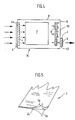
- FIG. 4 schematically shows a blower cooling unit 10, in which electronic components such as circuits, amplifiers, semiconductors, etc. are arranged, all of which are designated by 7.
- An air flow is generated by means of one or more fans 6, which are arranged on a rear wall 13 of the housing 8, the flow direction of which is indicated by arrows.
- the number of fans depends on the size of the housing 8 and the components 7 to be cooled.
- Axial and radial fans can be considered as fans 6.
- the air flow enters the housing 8 through an air inlet opening 11 and exits again through the air outlet opening 12 on the opposite side of the housing 8.
- the air inlet and air outlet openings 11, 12 are sealed with a protective cover 1, the protective cover being a watertight, porous material, so that the air sucked in by the fans 6 only passes through the protective cover 1 and thus filtered through the material 3 into the interior of the housing can.
- the protective covers 1 can optionally be arranged inside or outside the housing 8, as shown schematically in FIG.
- a gill plate 5 is attached on the outside in front of the protective cover 1 to protect against mechanical damage or vandalism.
- the air is preferably sucked in over the entire front surface of the housing 8, passed between the electrical components 7 and guided behind the fans 6 by means of baffles 9 to the air outlet opening 12.
- the baffles 9 help connect an air flow in the corners and direct the warm air to the air outlet opening 12.
- a typical dimension for a housing 8 of a base station or a control cabinet of telecommunication devices set up outdoors is 1500 x 1000 x 1000 mm 3 (H x W x D), while the protective cover 1 is for example a dimension of approximately 1000 x 450 x 100 mm 3 (H x W x D).
- the dimensions depend on the size of the housing 8 and the amount of air to be transported.
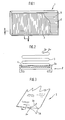
- Figures 1 to 3 is a special embodiment of the invention Protective cover 1 shown.
- Figure 1 shows a frame 2, which can be made of plastic or metal, being made of Stability and weight reasons aluminum is preferred.
- Frame 2 is a material 3 folded in a pleated form. The folding of the material 3 is to create a large one Air passage surface and also for self-stabilization of the material helpful.
- the depth of the frame 2 is so chosen that the two longitudinal side edges of the folded material 3rd does not protrude beyond the wall 2c of the frame 2, so that an airtight Connection between the material 3 and the frame 2 made can be to an air flow past the material 3 prevent.
- FIGs 1 and 2 is a rectangular frame 2 with the arranged therein, pleated material 3 shown lying in one plane.
- the pleated material 3 can be arranged in a circle, so that the side edges are closed by appropriate end caps 2a, 2b be (Fig. 6).
- the construction of such a cover, at the frame 2 is formed by two end caps 2a, 2b, corresponds essentially to a ring filter in the form of a cartridge.
- An end cap 2a has an opening 15 for air transport in To allow arrow direction.
- the end cap 2a with the opening 15 is connected to the housing 8.
- the material 3 in the frame 2 or between the End caps using a potting compound 4 such as polyurethane, polyvinyl chloride, Epoxy resin, silicone, hot melt adhesives or Plastisol attached.
- a potting compound 4 such as polyurethane, polyvinyl chloride, Epoxy resin, silicone, hot melt adhesives or Plastisol attached.
- the potting material 4 are chosen or treated so that it Material 3 soaked or at least so with the material surface connects that a continuous seal is ensured.
- silicones are well suited.
- Other potting materials such as Polyurethanes require additions of surfactants to make a complete To achieve wetting.
- surfactants can be related Plastics are used to better wet the surface.
- Preferred potting material that is chemically resistant and in particular is directly absorbed by ePTFE membrane material is a complete cross-linked silicone rubber polymer.
- the folded material 3 is cast with the frame 2 as follows. First, the folded material 3 is in the frame 2 used, and then all four walls 2c of the frame 2 shed with the material one after the other. This is the wall 2c, as seen in Figure 2, designed so that they are a kind of tub for the potting material 4 forms. After casting and curing the potting material 4 can then the next wall 2c with the Material 3 are shed.
- the gill plate 5 can simultaneously be potted. Such a gill plate 5 is partial in FIG shown broken away. The simultaneous shedding does it unnecessary to glue the gill plate 5 to the frame 2 to screw or fasten in any other way. In use cases, where cleaning of material 3 is to be expected is potting of the gill plate, however, does not make sense. In these cases there is a Screw to the frame 2 or to the housing 8 (see figure 4) preferable.
- the material 3 is porous and therefore air-permeable and waterproof. Both textile fabrics, e.g. Fabrics, knitted fabrics or fleeces, as well as membranes.
- a membrane is preferably made of stretched polytetrafluoroethylene film (ePTFE).
- ePTFE stretched polytetrafluoroethylene film
- they are also foils from other synthetic polymers such as polyethylene, polypropylene or other fluoropolymers including tetrafluoroethylene / (perfluoroalkyl) vinyl ether copolymer (PFA) or tetrafluoroethylene / hexafluoropropylene copolymer (FEP) suitable.
- a stretched polytetrafluoroethylene film is preferred as a membrane because it is porous and waterproof, a Temperature resistance up to 260 ° C and briefly up to 300 °, is naturally hydrophobic and due to a structure of each other connected nodes and fibrils penetrating the membrane thickness Porosity has a sufficiently high air flow allows.
- the production of such stretched polytetrafluoroethylene films is described in detail in Gore U.S. Patent 3,953,566 the content of which is expressly referred to here.
- the porosity and the size of the pores penetrating the membrane becomes important determined by the degree of stretching of the membrane.
- an ePTFE membrane with an average pore size of 0.5 to 20 ⁇ m, preferably 5 to 10 ⁇ m, especially 9 ⁇ m has been chosen for the protective cover according to the invention has been found to be particularly suitable, because this pore size in conjunction with those previously described Properties leads to a protective cover, its air flow even after a long period of use, not less than 60% of the air flow rate like-new coverage drops.
- Those materials which have a water inlet pressure are preferred withstand at least 0.2 bar, withstand against a water inlet pressure greater than 1 bar, e.g. with a 0.065 mm thick ePTFE membrane with 9 ⁇ m pore size can be reached, is preferred.
- the porosity results from the ratio of the apparent density of the material to the specific density of the material, where apparent density means the ratio of weight to total volume including pores and air pockets.
- Porosity means that the material has pores or air pockets. These can be completely closed and separate from one another, such as in a closed-cell foam. However, they can also be connected to one another and form a network of passages through the overall structure, as in an open-cell foam. However, there can also be a combination of both forms. Structures are preferred for the present application in which the porosity is largely formed by cells which are connected to one another and penetrate the structure.
- Pore size is determined by a standard procedure, ASTM procedure E1298-98, using a Coulter Porometer TM manufactured by Coulter Electronics Inc.
- the Coulter Porometer is an instrument that enables the automatic measurement of pore size distributions using the liquid displacement method ("liquid displacement method").
- the porometer determines the pore size distribution of a sample by increasing the air pressure on the sample and measuring the flow. This distribution is a measure of the degree of uniformity of the membrane (ie a narrow distribution means a small difference between the largest and the smallest pore sizes). It is determined by dividing the maximum pore size by the minimum pore size.
- the porometer also calculates the mean flow pore size. By definition, half of the liquid flow flows through the Filters through pores that are above or below this size. It is the medium flow pore size, mostly with different filter properties is linked to how the retention property with respect to particles in a flow of liquid. The maximum pore size is often associated with the Bubble point test is determined because compressed air first passes through the largest pores flowing.
- Hydrophobic means that a drop of water remains on the surface of the membrane as an almost spherical drop with a contact angle of over 90 °.
- Breathable may both porous and non-porous materials, especially membranes, being, and this term describes only the property that air can be transported through the material.
- the protective cover according to the invention uses porous materials, since this is the best way to ensure an effective and sufficiently high air throughput.
- the air throughput depends crucially on the pressure drop, the pore size and the material thickness. Pore sizes between 0.5 and 20 microns, preferably 5 to 10 microns, are practical. With a pore size of 9 ⁇ m and an effective material surface area of 6.5 m 2 , an air throughput of 200 m 3 / h was achieved if a negative pressure of 1.3 mbar was generated in the housing.
- the ePTFE membrane used had a thickness of 0.065 mm.
- the thickness of the material can be determined by means of a pharyngeal gauge or micrometer screw as an average of various measuring points.
- the air throughput can be determined, for example, using a Gurley density meter from W. & LE Gurley & Sons according to ASTM test method D726-58.
- Gurley number or Gurley seconds This is the time in seconds that it takes 100 ccm to flow through a 6.45 cm 2 sample material at a pressure drop of 12.4 cm.
- Flame retardant means that the material burns only in an environment with> 90% 0 2 content.
- Temperature-resistant means that the material retains the essential properties both at high (> 100 ° C) and at low ( ⁇ -45 ° C) temperatures.
- PTFE is temperature-resistant up to 260 ° C and briefly up to 300 ° C and maintains the essential properties even at temperatures of liquid nitrogen and in particular does not become brittle.
- waterproof means that the protective cover has a degree of protection of IP-55, that is to say that the water has no harmful effects when it is sprayed against the protective cover as a jet from any direction.
- the watertightness of a device equipped with the protective cover according to the invention with an ePTFE membrane was tested by setting up the device in the installed position and spraying it in four directions with a jet nozzle for 1 minute each. The directions were front and back, a side surface and the top. The protective cover was irradiated from different angles. The device was then opened without traces of water being found inside the device.
- the water inlet pressure is tested by stretching the material between two test plates. Water pressure is applied from one side, and water breakthrough is checked on the other side using pH paper 10 seconds after an increase in pressure. The water breakthrough pressure is the water inlet pressure.
- oleophobic is used when the material has an oil value or an oil repellency of> 1. Degrees of oil repellency of> 4 or preferably> 8 are particularly advantageous. The degree of oil repellency can be determined according to the AATCC test method 118-1989 ASTM. Further details on testing the oleophobicity, in particular of porous membranes, are described in detail in EP 0 816 043 A1, the content of which is hereby expressly incorporated by reference.
- the material shows in addition to the preferred ePTFE film 3a a support material 3b on the back of the material 3r, i.e. on the exhaust side of the material, on that as a fleece, fabric, Knitted fabric, mesh or perforated plate or other surface textile can be trained.
- the support material 3b is on the exhaust side of the Material 3 (material back) arranged to clog the support material 3b to prevent dirt particles, causing adverse effects on the air flow rate.
- the support material 3b can Example consist of polyester, polyamide, aramid or fluoropolymer. A polyester fleece is preferred. The manageability of the material 3 to facilitate, the two layers 3a, 3b laminated together become.
- the lamination is preferably only at individual points to be provided, otherwise the air throughput would be negatively affected. In some cases, however, a loose layer formation is preferable, especially when it comes to a maximum air flow or if due to the support material structure a relative displacement of the two layers when folding must be ensured.
- a additional support material 3c may be applied, which is basically similar can be constructed as the support material 3b on the exhaust side (see Fig. 5).
- a suitable material Has been particularly suitable the material REEMAY 2250, that of Reemay Incorporation is available.
- the material 3 can with the support materials 3b, 3c as 2-, 3- or be multilayer laminate.
- Blower cooling units were initially on various critical points of the housing thermocouples attached.
- the The device was installed in an accessible climatic chamber and operated electrically with a permanently programmed sequence.
- the Temperature testing took place at ambient temperatures between -33 ° C and + 55 ° C instead, the upper value still 10 ° above the European Telecommunication Standard ETS 300 019-1-4 (Feb. 1992) lies.
- the diodes showed after temperature adjustment during the Temperature cycle a maximum overtemperature of 3K to 5K compared to the ambient temperature. The other measured too Temperatures inside the device were in this temperature range.
Landscapes
- Microelectronics & Electronic Packaging (AREA)
- Engineering & Computer Science (AREA)
- Physics & Mathematics (AREA)
- Thermal Sciences (AREA)
- Chemical & Material Sciences (AREA)
- Chemical Kinetics & Catalysis (AREA)
- Separation Using Semi-Permeable Membranes (AREA)
- Casings For Electric Apparatus (AREA)
- Cooling Or The Like Of Electrical Apparatus (AREA)
- Filtering Of Dispersed Particles In Gases (AREA)
- Motor Or Generator Cooling System (AREA)
- Structures Of Non-Positive Displacement Pumps (AREA)
- Motor Or Generator Frames (AREA)
- Filtering Materials (AREA)
- Cookers (AREA)
- Electrophotography Configuration And Component (AREA)
- Thermistors And Varistors (AREA)
Applications Claiming Priority (3)
| Application Number | Priority Date | Filing Date | Title |
|---|---|---|---|
| DE19833247A DE19833247C2 (de) | 1998-07-23 | 1998-07-23 | Schutzabdeckung eines Gebläsekühlaggregats |
| DE19833247 | 1998-07-23 | ||
| EP99936593A EP1098692B1 (fr) | 1998-07-23 | 1999-07-22 | Couvercle de protection d'un systeme de refroidissement a courant d'air force |
Related Parent Applications (2)
| Application Number | Title | Priority Date | Filing Date |
|---|---|---|---|
| EP99936593.5 Division | 1999-07-22 | ||
| EP99936593A Division EP1098692B1 (fr) | 1998-07-23 | 1999-07-22 | Couvercle de protection d'un systeme de refroidissement a courant d'air force |
Publications (3)
| Publication Number | Publication Date |
|---|---|
| EP1351561A2 true EP1351561A2 (fr) | 2003-10-08 |
| EP1351561A3 EP1351561A3 (fr) | 2004-03-31 |
| EP1351561B1 EP1351561B1 (fr) | 2014-01-15 |
Family
ID=7875104
Family Applications (2)
| Application Number | Title | Priority Date | Filing Date |
|---|---|---|---|
| EP03010703.1A Expired - Lifetime EP1351561B1 (fr) | 1998-07-23 | 1999-07-22 | Couvercle de protection d'un système de refroidissement à courant d'air forcé |
| EP99936593A Expired - Lifetime EP1098692B1 (fr) | 1998-07-23 | 1999-07-22 | Couvercle de protection d'un systeme de refroidissement a courant d'air force |
Family Applications After (1)
| Application Number | Title | Priority Date | Filing Date |
|---|---|---|---|
| EP99936593A Expired - Lifetime EP1098692B1 (fr) | 1998-07-23 | 1999-07-22 | Couvercle de protection d'un systeme de refroidissement a courant d'air force |
Country Status (9)
| Country | Link |
|---|---|
| EP (2) | EP1351561B1 (fr) |
| JP (1) | JP2002521811A (fr) |
| KR (1) | KR100606523B1 (fr) |
| CN (1) | CN1122555C (fr) |
| AT (1) | ATE241417T1 (fr) |
| AU (1) | AU5163399A (fr) |
| DE (2) | DE19833247C2 (fr) |
| DK (1) | DK1098692T3 (fr) |
| WO (1) | WO2000004980A1 (fr) |
Cited By (3)
| Publication number | Priority date | Publication date | Assignee | Title |
|---|---|---|---|---|
| WO2005055384A1 (fr) * | 2003-12-04 | 2005-06-16 | Almatec Ag | Boitier a bords vifs a refroidissement a air |
| WO2005053819A1 (fr) * | 2003-11-26 | 2005-06-16 | Emerson Network Power, Energy Systems, North America, Inc. | Systeme de filtres pour enceinte d'equipement electronique |
| DE102004013173A1 (de) * | 2004-03-17 | 2005-10-13 | Fraunhofer-Gesellschaft zur Förderung der angewandten Forschung e.V. | Oleophobe anorganische Membranen und Verfahren zu deren Herstellung |
Families Citing this family (26)
| Publication number | Priority date | Publication date | Assignee | Title |
|---|---|---|---|---|
| DE10053681B4 (de) * | 2000-10-28 | 2004-08-26 | W.L. Gore & Associates Gmbh | Gehäuse mit mindestens einem EMI abschirmender Kunststoffkörper bzw. Be- und Entlüftungselement und Verfahren zur Herstellung eines solchen Kunststoffkörpers |
| US6675654B2 (en) | 2001-05-09 | 2004-01-13 | Endress + Hauser Gmbh + Co. Kg | Pressure sensing device with moisture filter |
| DE10122511A1 (de) * | 2001-05-09 | 2002-11-14 | Endress & Hauser Gmbh & Co Kg | Relativdrucksensor mit Feuchtefilter |
| JP4366942B2 (ja) * | 2003-01-29 | 2009-11-18 | 旭硝子株式会社 | キャリアフィルム及びその製造方法 |
| CA2518411C (fr) * | 2003-03-05 | 2010-05-25 | Nec Corporation | Refroidisseur utilisant un filtre comportant une fonction de deshumidification |
| DE102005023446A1 (de) * | 2005-05-20 | 2006-11-23 | BSH Bosch und Siemens Hausgeräte GmbH | Haushaltgerät zur Pflege von Wäschestücken, insbesondere Wäschetrockner |
| ATE502514T1 (de) * | 2005-07-14 | 2011-04-15 | Gore W L & Ass Gmbh | Kühllüftereinheit zum kühlen von elektronischen bauelementen |
| DE202005020260U1 (de) * | 2005-12-23 | 2007-05-10 | Mann + Hummel Gmbh | Filterelement |
| KR101248955B1 (ko) * | 2006-07-27 | 2013-03-29 | 한라공조주식회사 | 팬 콘트롤러의 내부 압력 및 온도 유지를 위한 에어벤트구조 |
| DE202006012058U1 (de) | 2006-08-07 | 2007-12-20 | Pfannenberg Gmbh | Luftdurchtrittsvorrichtung mit einer verbesserten Zugänglichkeit der Filtermatte |
| DE102006047316A1 (de) * | 2006-10-06 | 2008-04-10 | Pfannenberg Gmbh | Filterlüfter |
| EP1939456B1 (fr) | 2006-12-27 | 2014-03-12 | Pfannenberg GmbH | Dispositif de passage d'air |
| US7837756B2 (en) | 2007-04-05 | 2010-11-23 | Aaf-Mcquay Inc. | Filter with ePTFE and method of forming |
| US7927405B2 (en) * | 2007-04-23 | 2011-04-19 | Gore Enterprise Holdings, Inc | Porous composite article |
| US20090002941A1 (en) * | 2007-06-29 | 2009-01-01 | Rajiv Mongia | Air-permeable, hydrophobic membrane used in a computer device |
| AU2011254022B2 (en) * | 2009-06-12 | 2014-02-13 | Parker-Hannifin Corporation | Membrane-free filter and/or integral framing for filter |
| CN102458608B (zh) * | 2009-06-12 | 2016-08-31 | 克拉克空气过滤产品有限公司 | 无薄膜过滤器和/或用于过滤器的整体框架 |
| KR101129169B1 (ko) * | 2009-11-25 | 2012-03-26 | 코리아에어텍 주식회사 | 팬형식 냉각장치용 필터 및 이를 구비한 필터조립체 |
| CN103180887B (zh) * | 2010-07-22 | 2016-11-09 | 克拉克空气过滤产品有限公司 | 结合有防水过滤器的自助式服务终端机 |
| KR20160020103A (ko) | 2014-08-13 | 2016-02-23 | (주)에프티이앤이 | 전자기기 보호용 필터매체 및 이를 포함하는 필터 조립체 |
| CN105806003A (zh) * | 2014-12-30 | 2016-07-27 | 青岛海尔智能技术研发有限公司 | 风冷冰箱 |
| DE102015215535B4 (de) * | 2015-08-14 | 2019-02-21 | SCHäFER WERKE GMBH | Kühleinrichtung mit einem Wärmetauscher und einem Spritzschutz sowie Vorrichtung mit einem Gehäuse und einer solchen Kühleinrichtung |
| DE102016201723B4 (de) * | 2016-02-04 | 2019-03-07 | SCHäFER WERKE GMBH | Sidecooler mit einem Wärmetauscher zur Anordnung neben einem Schrank für elektronische Komponenten |
| DE202016001447U1 (de) | 2016-03-03 | 2016-04-25 | André Runge | Vorrichtung zum Kühlen elektrischer und elektronischer Komponenten |
| KR20160118169A (ko) | 2016-09-22 | 2016-10-11 | (주)에프티이앤이 | 전자기기 보호용 필터매체 및 이를 포함하는 필터 조립체 |
| CN109405401A (zh) * | 2018-10-17 | 2019-03-01 | 合肥华凌股份有限公司 | 制冷设备的壳体及制冷设备 |
Family Cites Families (13)
| Publication number | Priority date | Publication date | Assignee | Title |
|---|---|---|---|---|
| CA962021A (en) * | 1970-05-21 | 1975-02-04 | Robert W. Gore | Porous products and process therefor |
| US4228975A (en) * | 1979-05-29 | 1980-10-21 | The Boeing Company | Kneeling nose landing gear assembly |
| GB2147663A (en) * | 1983-09-22 | 1985-05-15 | Terence Furdson Crang | Cooling by a stream of filtered air or gas |
| EP0311702B1 (fr) * | 1987-10-14 | 1992-05-20 | Schroff GmbH | Boîtier pour tiroir |
| JP2788976B2 (ja) * | 1989-04-26 | 1998-08-20 | ジャパンゴアテック株式会社 | フィルター材 |
| DE4210979C2 (de) * | 1992-04-02 | 1995-07-13 | Reinshagen Kabelwerk Gmbh | Wasserdichtes Gehäuse |
| DE4234919C2 (de) * | 1992-10-16 | 1994-11-17 | Audi Ag | Gehäuse mit einer darin angeordneten Wärmequelle, insbesondere an einem Kraftfahrzeug |
| DE4308369C2 (de) * | 1993-03-16 | 2001-02-01 | Gore & Ass | Oleophob modifizierte mikroporöse Polymere |
| US5460872A (en) * | 1993-03-26 | 1995-10-24 | W. L. Gore & Associates, Inc. | Process for coating microporous substrates and products therefrom |
| US5539072A (en) * | 1993-03-26 | 1996-07-23 | W. L. Gore & Associates, Inc. | Fabric laminates |
| US5507847A (en) * | 1994-07-29 | 1996-04-16 | W. L. Gore & Associates, Inc. | ULPA filter |
| US5536290A (en) * | 1995-02-17 | 1996-07-16 | W. L. Gore & Associates, Inc. | Pleated cartridge filter attachment for top loading filter assemblies |
| US5783086A (en) * | 1995-09-29 | 1998-07-21 | W. L. Gore & Associates, Inc. | Filter for a wet/dry vacuum cleaner for wet material collection |
-
1998
- 1998-07-23 DE DE19833247A patent/DE19833247C2/de not_active Expired - Lifetime
-
1999
- 1999-07-22 DK DK99936593T patent/DK1098692T3/da active
- 1999-07-22 AU AU51633/99A patent/AU5163399A/en not_active Abandoned
- 1999-07-22 EP EP03010703.1A patent/EP1351561B1/fr not_active Expired - Lifetime
- 1999-07-22 EP EP99936593A patent/EP1098692B1/fr not_active Expired - Lifetime
- 1999-07-22 WO PCT/EP1999/005255 patent/WO2000004980A1/fr not_active Ceased
- 1999-07-22 CN CN99807800A patent/CN1122555C/zh not_active Expired - Fee Related
- 1999-07-22 DE DE59905759T patent/DE59905759D1/de not_active Expired - Lifetime
- 1999-07-22 KR KR1020007013423A patent/KR100606523B1/ko not_active Expired - Fee Related
- 1999-07-22 JP JP2000560966A patent/JP2002521811A/ja active Pending
- 1999-07-22 AT AT99936593T patent/ATE241417T1/de not_active IP Right Cessation
Non-Patent Citations (1)
| Title |
|---|
| None |
Cited By (5)
| Publication number | Priority date | Publication date | Assignee | Title |
|---|---|---|---|---|
| WO2005053819A1 (fr) * | 2003-11-26 | 2005-06-16 | Emerson Network Power, Energy Systems, North America, Inc. | Systeme de filtres pour enceinte d'equipement electronique |
| US7455706B2 (en) | 2003-11-26 | 2008-11-25 | Emerson Network Power, Energy Systems, North America, Inc. | Filter system for electronic equipment enclosure |
| WO2005055384A1 (fr) * | 2003-12-04 | 2005-06-16 | Almatec Ag | Boitier a bords vifs a refroidissement a air |
| DE102004013173A1 (de) * | 2004-03-17 | 2005-10-13 | Fraunhofer-Gesellschaft zur Förderung der angewandten Forschung e.V. | Oleophobe anorganische Membranen und Verfahren zu deren Herstellung |
| DE102004013173B4 (de) * | 2004-03-17 | 2006-04-13 | Fraunhofer-Gesellschaft zur Förderung der angewandten Forschung e.V. | Oleophobe anorganische Membranen und Verfahren zu deren Herstellung |
Also Published As
| Publication number | Publication date |
|---|---|
| ATE241417T1 (de) | 2003-06-15 |
| EP1098692A1 (fr) | 2001-05-16 |
| CN1306453A (zh) | 2001-08-01 |
| CN1122555C (zh) | 2003-10-01 |
| DE19833247A1 (de) | 2000-02-03 |
| JP2002521811A (ja) | 2002-07-16 |
| DE59905759D1 (de) | 2003-07-03 |
| DE19833247C2 (de) | 2000-10-26 |
| DK1098692T3 (da) | 2003-09-01 |
| WO2000004980A1 (fr) | 2000-02-03 |
| EP1351561A3 (fr) | 2004-03-31 |
| EP1351561B1 (fr) | 2014-01-15 |
| KR20010052429A (ko) | 2001-06-25 |
| AU5163399A (en) | 2000-02-14 |
| KR100606523B1 (ko) | 2006-08-01 |
| EP1098692B1 (fr) | 2003-05-28 |
Similar Documents
| Publication | Publication Date | Title |
|---|---|---|
| EP1098692B1 (fr) | Couvercle de protection d'un systeme de refroidissement a courant d'air force | |
| EP1750493B1 (fr) | Unité de refroidissement pour refroidir des composants électroniques | |
| DE602004009463T2 (de) | Luftfilter für Turbineneinlass | |
| DE10053681B4 (de) | Gehäuse mit mindestens einem EMI abschirmender Kunststoffkörper bzw. Be- und Entlüftungselement und Verfahren zur Herstellung eines solchen Kunststoffkörpers | |
| US5342434A (en) | Gas permeable coated porous membranes | |
| AU675019B2 (en) | ULPA filter | |
| CN102802759B (zh) | 结合无薄膜过滤器和/或用于过滤器整体框架的空气冷却系统 | |
| US5506047A (en) | Electromagnetic interfernce shielding filter | |
| KR101393173B1 (ko) | 미세다공성 기재 상의 다작용성 코팅 | |
| DE102009003524A1 (de) | Laminierter oleophober Gegenstand | |
| DE202014011240U1 (de) | Lüftungselement | |
| DE102011000945A1 (de) | Herstellungsverfahren für einen Gegenstand aus Verbundwerkstoff | |
| DE102011054869A1 (de) | Laminierter oleophober Gegenstand | |
| DE102011052843A1 (de) | Eine gedruckte gemusterte Teilchenschicht enthaltende oleophobe Membran und Verfahren | |
| WO1994013385A1 (fr) | Materiaux permeables aux gaz | |
| DE102011053271A1 (de) | Atmungsfähige Abdichtung | |
| DE602004010495T2 (de) | Heiz-, ventilations- und klimatisierungssystem mit einem folienventil und folie zur steuerung eines luftstroms | |
| DE102010015610B4 (de) | Dichtring mit Membranventil | |
| DE3501621C2 (fr) | ||
| DE102007045783B4 (de) | Verfahren zur Herstellung einer elastischen mikroporösen Membran, Membran hergestellt nach dem Verfahren und deren Verwendung | |
| US20070077407A1 (en) | Composite article having oleophobic properties and method of manufacture | |
| TW202330080A (zh) | 通氣過濾器及通氣構件 | |
| DE202006003488U1 (de) | Klimatisierung von in einem Gehäuse aufgenommenen elektronischen Bauteilen | |
| EP3214912A1 (fr) | Dispositif et procédé de refroidissement de composants électriques et électroniques |
Legal Events
| Date | Code | Title | Description |
|---|---|---|---|
| PUAI | Public reference made under article 153(3) epc to a published international application that has entered the european phase |
Free format text: ORIGINAL CODE: 0009012 |
|
| AC | Divisional application: reference to earlier application |
Ref document number: 1098692 Country of ref document: EP Kind code of ref document: P |
|
| AK | Designated contracting states |
Kind code of ref document: A2 Designated state(s): AT BE CH CY DE DK ES FI FR GB GR IE IT LI LU MC NL PT SE |
|
| PUAL | Search report despatched |
Free format text: ORIGINAL CODE: 0009013 |
|
| AK | Designated contracting states |
Kind code of ref document: A3 Designated state(s): AT BE CH CY DE DK ES FI FR GB GR IE IT LI LU MC NL PT SE |
|
| 17P | Request for examination filed |
Effective date: 20030603 |
|
| AKX | Designation fees paid |
Designated state(s): AT BE CH CY DE DK ES FI FR GB GR IE IT LI LU MC NL PT SE |
|
| 17Q | First examination report despatched |
Effective date: 20100126 |
|
| GRAP | Despatch of communication of intention to grant a patent |
Free format text: ORIGINAL CODE: EPIDOSNIGR1 |
|
| RIC1 | Information provided on ipc code assigned before grant |
Ipc: H05K 7/20 20060101AFI20130717BHEP Ipc: H05K 5/02 20060101ALI20130717BHEP |
|
| INTG | Intention to grant announced |
Effective date: 20130806 |
|
| GRAS | Grant fee paid |
Free format text: ORIGINAL CODE: EPIDOSNIGR3 |
|
| GRAA | (expected) grant |
Free format text: ORIGINAL CODE: 0009210 |
|
| AC | Divisional application: reference to earlier application |
Ref document number: 1098692 Country of ref document: EP Kind code of ref document: P |
|
| AK | Designated contracting states |
Kind code of ref document: B1 Designated state(s): AT BE CH CY DE DK ES FI FR GB GR IE IT LI LU MC NL PT SE |
|
| REG | Reference to a national code |
Ref country code: CH Ref legal event code: EP Ref country code: GB Ref legal event code: FG4D Free format text: NOT ENGLISH |
|
| REG | Reference to a national code |
Ref country code: AT Ref legal event code: REF Ref document number: 650325 Country of ref document: AT Kind code of ref document: T Effective date: 20140215 |
|
| REG | Reference to a national code |
Ref country code: IE Ref legal event code: FG4D Free format text: LANGUAGE OF EP DOCUMENT: GERMAN |
|
| REG | Reference to a national code |
Ref country code: DE Ref legal event code: R096 Ref document number: 59915399 Country of ref document: DE Effective date: 20140227 |
|
| REG | Reference to a national code |
Ref country code: SE Ref legal event code: TRGR |
|
| REG | Reference to a national code |
Ref country code: NL Ref legal event code: VDEP Effective date: 20140115 |
|
| PG25 | Lapsed in a contracting state [announced via postgrant information from national office to epo] |
Ref country code: ES Free format text: LAPSE BECAUSE OF FAILURE TO SUBMIT A TRANSLATION OF THE DESCRIPTION OR TO PAY THE FEE WITHIN THE PRESCRIBED TIME-LIMIT Effective date: 20140115 Ref country code: FI Free format text: LAPSE BECAUSE OF FAILURE TO SUBMIT A TRANSLATION OF THE DESCRIPTION OR TO PAY THE FEE WITHIN THE PRESCRIBED TIME-LIMIT Effective date: 20140115 Ref country code: PT Free format text: LAPSE BECAUSE OF FAILURE TO SUBMIT A TRANSLATION OF THE DESCRIPTION OR TO PAY THE FEE WITHIN THE PRESCRIBED TIME-LIMIT Effective date: 20140515 Ref country code: NL Free format text: LAPSE BECAUSE OF FAILURE TO SUBMIT A TRANSLATION OF THE DESCRIPTION OR TO PAY THE FEE WITHIN THE PRESCRIBED TIME-LIMIT Effective date: 20140115 Ref country code: CY Free format text: LAPSE BECAUSE OF FAILURE TO SUBMIT A TRANSLATION OF THE DESCRIPTION OR TO PAY THE FEE WITHIN THE PRESCRIBED TIME-LIMIT Effective date: 20140115 |
|
| REG | Reference to a national code |
Ref country code: DE Ref legal event code: R097 Ref document number: 59915399 Country of ref document: DE |
|
| PG25 | Lapsed in a contracting state [announced via postgrant information from national office to epo] |
Ref country code: DK Free format text: LAPSE BECAUSE OF FAILURE TO SUBMIT A TRANSLATION OF THE DESCRIPTION OR TO PAY THE FEE WITHIN THE PRESCRIBED TIME-LIMIT Effective date: 20140115 |
|
| PLBE | No opposition filed within time limit |
Free format text: ORIGINAL CODE: 0009261 |
|
| STAA | Information on the status of an ep patent application or granted ep patent |
Free format text: STATUS: NO OPPOSITION FILED WITHIN TIME LIMIT |
|
| 26N | No opposition filed |
Effective date: 20141016 |
|
| REG | Reference to a national code |
Ref country code: DE Ref legal event code: R097 Ref document number: 59915399 Country of ref document: DE Effective date: 20141016 |
|
| PG25 | Lapsed in a contracting state [announced via postgrant information from national office to epo] |
Ref country code: LU Free format text: LAPSE BECAUSE OF FAILURE TO SUBMIT A TRANSLATION OF THE DESCRIPTION OR TO PAY THE FEE WITHIN THE PRESCRIBED TIME-LIMIT Effective date: 20140722 |
|
| REG | Reference to a national code |
Ref country code: CH Ref legal event code: PL |
|
| REG | Reference to a national code |
Ref country code: IE Ref legal event code: MM4A |
|
| REG | Reference to a national code |
Ref country code: FR Ref legal event code: ST Effective date: 20150331 |
|
| PG25 | Lapsed in a contracting state [announced via postgrant information from national office to epo] |
Ref country code: CH Free format text: LAPSE BECAUSE OF NON-PAYMENT OF DUE FEES Effective date: 20140731 Ref country code: LI Free format text: LAPSE BECAUSE OF NON-PAYMENT OF DUE FEES Effective date: 20140731 |
|
| PG25 | Lapsed in a contracting state [announced via postgrant information from national office to epo] |
Ref country code: FR Free format text: LAPSE BECAUSE OF NON-PAYMENT OF DUE FEES Effective date: 20140731 |
|
| PG25 | Lapsed in a contracting state [announced via postgrant information from national office to epo] |
Ref country code: IE Free format text: LAPSE BECAUSE OF NON-PAYMENT OF DUE FEES Effective date: 20140722 |
|
| REG | Reference to a national code |
Ref country code: AT Ref legal event code: MM01 Ref document number: 650325 Country of ref document: AT Kind code of ref document: T Effective date: 20140722 |
|
| PG25 | Lapsed in a contracting state [announced via postgrant information from national office to epo] |
Ref country code: AT Free format text: LAPSE BECAUSE OF NON-PAYMENT OF DUE FEES Effective date: 20140722 |
|
| PG25 | Lapsed in a contracting state [announced via postgrant information from national office to epo] |
Ref country code: MC Free format text: LAPSE BECAUSE OF FAILURE TO SUBMIT A TRANSLATION OF THE DESCRIPTION OR TO PAY THE FEE WITHIN THE PRESCRIBED TIME-LIMIT Effective date: 20140115 |
|
| PG25 | Lapsed in a contracting state [announced via postgrant information from national office to epo] |
Ref country code: IT Free format text: LAPSE BECAUSE OF FAILURE TO SUBMIT A TRANSLATION OF THE DESCRIPTION OR TO PAY THE FEE WITHIN THE PRESCRIBED TIME-LIMIT Effective date: 20140115 Ref country code: GR Free format text: LAPSE BECAUSE OF FAILURE TO SUBMIT A TRANSLATION OF THE DESCRIPTION OR TO PAY THE FEE WITHIN THE PRESCRIBED TIME-LIMIT Effective date: 20140416 |
|
| PG25 | Lapsed in a contracting state [announced via postgrant information from national office to epo] |
Ref country code: BE Free format text: LAPSE BECAUSE OF FAILURE TO SUBMIT A TRANSLATION OF THE DESCRIPTION OR TO PAY THE FEE WITHIN THE PRESCRIBED TIME-LIMIT Effective date: 20140731 |
|
| PGFP | Annual fee paid to national office [announced via postgrant information from national office to epo] |
Ref country code: GB Payment date: 20170620 Year of fee payment: 19 |
|
| PGFP | Annual fee paid to national office [announced via postgrant information from national office to epo] |
Ref country code: SE Payment date: 20170626 Year of fee payment: 19 |
|
| PGFP | Annual fee paid to national office [announced via postgrant information from national office to epo] |
Ref country code: DE Payment date: 20170620 Year of fee payment: 19 |
|
| REG | Reference to a national code |
Ref country code: DE Ref legal event code: R119 Ref document number: 59915399 Country of ref document: DE |
|
| GBPC | Gb: european patent ceased through non-payment of renewal fee |
Effective date: 20180722 |
|
| PG25 | Lapsed in a contracting state [announced via postgrant information from national office to epo] |
Ref country code: DE Free format text: LAPSE BECAUSE OF NON-PAYMENT OF DUE FEES Effective date: 20190201 Ref country code: GB Free format text: LAPSE BECAUSE OF NON-PAYMENT OF DUE FEES Effective date: 20180722 |
|
| PG25 | Lapsed in a contracting state [announced via postgrant information from national office to epo] |
Ref country code: SE Free format text: LAPSE BECAUSE OF NON-PAYMENT OF DUE FEES Effective date: 20180723 |