EP1351599B2 - Höheneinstellmechanismus - Google Patents
Höheneinstellmechanismus Download PDFInfo
- Publication number
- EP1351599B2 EP1351599B2 EP01271172A EP01271172A EP1351599B2 EP 1351599 B2 EP1351599 B2 EP 1351599B2 EP 01271172 A EP01271172 A EP 01271172A EP 01271172 A EP01271172 A EP 01271172A EP 1351599 B2 EP1351599 B2 EP 1351599B2
- Authority
- EP
- European Patent Office
- Prior art keywords
- socket
- unlocking lever
- rack
- locking mechanism
- supporting piece
- Prior art date
- Legal status (The legal status is an assumption and is not a legal conclusion. Google has not performed a legal analysis and makes no representation as to the accuracy of the status listed.)
- Expired - Lifetime
Links
- 230000007246 mechanism Effects 0.000 title claims abstract description 77
- 230000004888 barrier function Effects 0.000 claims description 7
- 230000000284 resting effect Effects 0.000 claims 1
- 238000000034 method Methods 0.000 description 2
- 230000001419 dependent effect Effects 0.000 description 1
- 230000005484 gravity Effects 0.000 description 1
Images


Classifications
-
- A—HUMAN NECESSITIES
- A47—FURNITURE; DOMESTIC ARTICLES OR APPLIANCES; COFFEE MILLS; SPICE MILLS; SUCTION CLEANERS IN GENERAL
- A47L—DOMESTIC WASHING OR CLEANING; SUCTION CLEANERS IN GENERAL
- A47L15/00—Washing or rinsing machines for crockery or tableware
- A47L15/42—Details
- A47L15/50—Racks ; Baskets
- A47L15/504—Arrangements for changing the height of racks
Definitions
- the present invention relates to the vertical adjustment of the dishwasher rack used in dishwashers.
- the object of the present invention is to provide the adjustment of the dishwasher rack height inside the dishwasher cabinet.
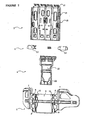
- the vertical adjustment mechanism (1) comprises a body (2), an unlocking lever (4) placed on said body (2), a locking mechanism (5) located between said body (2) and the unlocking lever (4) and, a supporting piece (3) on which the body (2) is attached.
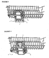
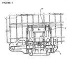
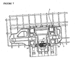
- Said vertical adjustment mechanism (1) is placed on both sides of the rack and when the user wants to move the rack upwards or downwards, she actuates the unlocking lever (4) and the locking mechanism (5) by applying force on the unlocking lever (4) and as the result of this movement, the body (2) and the rack attached to said body (2) moves on the supporting piece (3).
- the sliding guide projections (15) provided on both sides of the body (2) are attached to the sliding guides (7) on the supporting piece (3). Furthermore, the body (2) is allowed to move easily without deviating from its movement direction, on the supporting piece (3) placed on the rails (13) by means of the guide projections (8).
- Projections (19a) provided at the inner sides of the unlocking lever socket (14a) to prevent the unlocking lever (4) from escaping out of its socket (14a).
- Said projections (19a) are preferably made in a cascading form, in order to minimize the movements of the unlocking lever (4) in its socket (14a).
- Stoppers (12a) that prevent the unlocking lever (4) from escaping, in vertical direction, from the body (2), are provided on the body (2), below the unlocking lever socket (14a).
- a barrier (32) delimiting the horizontal movement of the unlocking lever (4), and extending along the unlocking lever socket (14a), is located.
- Stoppers (12b) that prevent the locking mechanism (5) to release from the lock socket (14b) are provided at both ends of the lock socket (14b) and at places corresponding the recesses formed at the edges of the locking mechanism (5) of the lock socket (14b).
- the movement of the locking mechanism (5) is limited by the lateral wall of the lock socket (14b).
- Said lock socket (14b) is provided with one or more grooves (16) that allow the easy attachment of the locking mechanism (5).
- the spring (28) is disposed in the spring recess (27) provided in the central portion (31) of the first bolt (24).
- Second bolt (25) is so placed in the spring recess (27) that the supporting surface (29) will be in contact with the spring (28).
- Said first and second bolts (24,25) are brought close to each other and the spring (28) is compressed in order to place the locking mechanism (5) into the lock socket (14b) provided on the body (2).
- Said rack may be elevated by the user, applying a force onto the catch bar (20) provided at the upper section of the unlocking lever (4) or directly onto the rack.
- said rack can be raised/lowered as a whole by pulling simultaneously both unlocking levers (4) of the vertical adjustment mechanism (1) located at both sides of the rack, or first a part of the rack can be raised/lowered by pulling one of the unlocking levers (4) and then the other a part of the rack can be raised/lowered by pulling the other unlocking lever (4).
- one upper locking socket (10) is located on the supporting piece (3), in the above disclosed embodiments, more than one locking socket (10) may also be used in order to enable the rack to be kept at more than one level.
Landscapes
- Washing And Drying Of Tableware (AREA)
- Drawers Of Furniture (AREA)
- Vehicle Body Suspensions (AREA)
- Fittings On The Vehicle Exterior For Carrying Loads, And Devices For Holding Or Mounting Articles (AREA)
- Auxiliary Devices For And Details Of Packaging Control (AREA)
- Absorbent Articles And Supports Therefor (AREA)
- Paper (AREA)
- Memory System Of A Hierarchy Structure (AREA)
- Handcart (AREA)
Claims (8)
- Vertikalverstellmechanismus zur Verwendung in Geschirrspülmaschinen, der an beiden gegenüberliegenden Seiten des Ablagegestells angeordnet ist, und der einen Grundkörper (2), einen Entriegelungshebel (4), der in einer Entriegelungshebelsteckhülse (14a) am genannten Grundkörper (2) angeordnet ist, einen Verriegelungsmechanismus (5), der in einer Verriegelungssteckhülse (14b) am genannten Grundkörper (2) angeordnet ist, und ein Halteelement (3) umfasst, an dem der Grundkörper (2) angebracht ist, wodurch das Ablagegestell sich mittels der Bewegung des Grundkörpers (2) am Haltelement (3) bewegen kann, wenn zum Entriegeln des Verriegelungsmechanismus (5) eine Kraft in Aufwärtsrichtung (A) auf den Entriegelungshebel (4) angewandt wird, der am Grundkörper (2) vorgesehen ist, oder direkt auf das Ablagegestell angewandt wird, wodurch sich der Entriegelungshebel (4) in die Entriegelungshebelsteckhülse (14a) nach oben bewegt,
wobei der genannte Entriegelungshebel (4) in Übereinstimmung mit dem Verriegelungsmechanismus (5) gelangt, wenn eine Kraft in Aufwärtsrichtung (A) angewandt wird, um den Verriegelungsmechanismus (5) zu entriegeln,
wobei der genannte Entriegelungshebel (4) dazu dient, den Verriegelungsmechanismus (5) sowohl zum Anheben als auch zum Absenken des Ablagegestells zu entriegeln. - Vertikalverstellmechanismus nach Anspruch 1, dadurch gekennzeichnet, dass das Halteelement (3) an seiner Stirnfläche ein Paar Räder (6) und an seiner Rückenfläche die Gleitfiihrungselemente (7) umfasst, die das Eingreifen des Körpers (2) erleichtern, einen oder mehrere Führungsvorsprünge (8) zwischen den genannten Gleitfiihrungselementen (7), einen Kanal (9), in dem sich der Entriegelungshebel (4) und der Verriegelungsmechanismus (5) bewegen, zwischen den genannten Führungsvorsprüngen (8), und mindestens eine obere Verriegelungssteckhülse (10), in die der Verriegelungsmechanismus (5) eingesetzt ist und verriegelt bleibt, und die es erlaubt, dass sich das Ablagegestell durch die Bewegung der Räder (6) an den Schienen in der Geschirrspülmaschine vor und zurück bewegt.
- Vertikalverstellmechanismus (1) nach den Ansprüchen 1 und 2, dadurch gekennzeichnet, dass der Grundkörper (2), der am Halteelement (3) angeordnet ist, Ablagegestellhalterungen (11) umfasst, die ein Anbringen des Grundkörpers (2) an den horizontalen und/oder längs verlaufenden Stäben des Ablagegestells erlauben, einen Anschlag (12a), der während der Bewegung am Halteelement (3) sein Heraustreten aus dem Halteelement (3) verhindert, Gleitführungsvorsprünge (15), die an den Gleitfiihrungselementen (7) am Halteelement (3) angebracht sind, Schienen (13), die in den Führungsvorsprüngen (8) am Halteelement (3) angeordnet sind, und die es ihm erlauben, sich leichtgängig und ohne Abweichung von seiner Bewegungsrichtung am Halteelement (3) zu bewegen, und eine Steckhülse (14), die einen Entriegelungshebelsteckhülse (14a) umfasst, in der der Entriegelungshebel (4) angeordnet ist, und eine Verriegelungssteckhülse (14b), in der der Verriegelungsmechanismus (5) angeordnet ist.
- Vertikalverstellmechanismus (1) nach den Ansprüchen 1 bis 3, dadurch gekennzeichnet, dass die Steckhülse (14) am Grundkörper (2) Entriegelungshebelsteckhülse (14a) mit Vorsprüngen (19a) umfasst, die verhindern, dass der Entriegelungshebel (4) aus seiner Steckhülse (14a) austritt, und in ihrer Mitte eine Barriere (32), die die horizontale Bewegung des Entriegelungshebels (4) begrenzt, und eine Verriegelungssteckhülse (14b) mit Anschlägen (12b) an beiden Enden der Verriegelungssteckhülse (14b) und an Positionen, die den Vertiefungen entsprechen, welche an den Kanten des Verriegelungsmechanismus (5) ausgebildet sind, die verhindern, dass der Verriegelungsmechanismus (5) die Verriegelungssteckhülse (14b) verlässt, und Nuten (16), die eine leichte Anbringung des Verriegelungsmechanismus (5) erlauben.
- Vertikalverstellmechanismus (1) nach den Ansprüchen 1 bis 4, dadurch gekennzeichnet, dass der Entriegelungshebel (4) einen Sperrhebel (20) umfasst, auf den Kraft angewandt wird, einen Entriegelungshebelrahmen (18), an dem die Vorsprünge (19b) vorgesehen sind, die den gleichen kaskadierenden Aufbau aufweisen wie die Vorsprünge (19a), die an den Innenseiten der Entriegelungshebelsteckhülse (14a) vorgesehen sind, eine Schrauböffnung (17), wobei im unteren Abschnitt der Schrauböffnung (17) Kontaktflächen (21) angeordnet sind, einen Entriegelungshebelkanal (22), der in Eingriff mit der Barriere (32) gelangt, die sich an der Mitte der Steckhülse (14) entlang erstreckt.
- Vertikalverstellmechanismus(1) nach den Ansprüchen 1 bis 5, dadurch gekennzeichnet, dass der Verriegelungsmechanismus (5) eine erste Schraube (24) umfasst, die einen Endabschnitt (30), einen Mittelabschnitt (31), an dem genannten Endabschnitt (30) eine geneigte Fläche, die die Bewegung des Verriegelungsmechanismus (5) im Kanal (9), der am Halteelement (3) und an dem Mittelabschnitt (31) vorgesehen ist, erleichtert, eine oder mehrere gewinkelte Flächen (26) und eine Federvertiefung (27) umfasst, eine zweite Schraube (25), in deren Mittelabschnitt (31) in einer Position gegenüber der ersten Schraube (24), eine Haltefläche (29) vorgesehen ist, derart, dass sie in die Federvertiefung (27) der ersten Schraube (24) eintritt, und eine Feder (28), die in der Federvertiefung (27) der ersten Schraube (24) angeordnet ist, und die die erste und zweite Schraube (24 und 25) verbindet, indem sie an der Haltefläche (29) am Mittelabschnitt (31) der zweiten Schraube (25) ruht.
- Vertikalverstellmechanismus (1) nach Anspruch 6, dadurch gekennzeichnet, dass der Verriegelungsmechanismus (5) gewinkelte Schraubflächen (26) umfasst, die die gleiche Form aufweisen wie die Kontaktflächen (21), die am unteren Teil der Verriegelungshandöffnung (17) vorgesehen sind.
- Vertikalverstellmechanismus (1) nach den Ansprüchen 1 bis 6, der zusammengebaut wird, indem der Verriegelungsmechanismus (5), der gebildet ist, indem die Feder (28) zwischen die erste und zweite Schraube (24, 25) gesetzt ist, in die Verriegelungssteckhülse (14b) gesetzt wird, die am Grundkörper (2) vorgesehen ist, der Entriegelungshebel (4) in die Entriegelungshebelsteckhülse (14a) gesetzt wird, die am Grundkörper (2) vorgesehen ist, und der genannte Grundkörper (2) mit dem Entriegelungshebel (4) und dem Verriegelungsmechanismus (5) am Halteelement (3) angebracht wird, was die Aufwärtsbewegung des Grundkörpers (2) im Kanal (9) ermöglicht, der am Halteelement (3) vorgesehen ist, wenn der Benutzer das Ablagegestell anheben möchte, indem er eine Kraft auf den Klinkenhebel (20) oder auf das Ablagegestell ausübt, und das Ablagegestell fixiert hält, indem der Verriegelungsmechanismus (5) in die obere Verriegelungssteckhülse (10) eingreifen lässt, und wenn der Benutzer das Ablagegestell absenken möchte, die Aufwärtsbewegung des Entriegelungshebels (4) in die Entriegelungshebelsteckhülse (14a) ermöglicht, was wiederum den Verriegelungsmechanismus (5) veranlasst, die obere Verriegelungssteckhülse (10) zu verlassen, und den Grundkörper (2), sich im Kanal (9), der am Halteelement (3) vorgesehen ist, nach unten zu bewegen.
Priority Applications (1)
| Application Number | Priority Date | Filing Date | Title |
|---|---|---|---|
| DE60130796T DE60130796T3 (de) | 2000-12-19 | 2001-12-19 | Höheneinstellmechanismus |
Applications Claiming Priority (3)
| Application Number | Priority Date | Filing Date | Title |
|---|---|---|---|
| TR200003780 | 2000-12-19 | ||
| TR200003780 | 2000-12-19 | ||
| PCT/TR2001/000064 WO2002049495A1 (en) | 2000-12-19 | 2001-12-19 | Vertical adjustment mechanism |
Publications (3)
| Publication Number | Publication Date |
|---|---|
| EP1351599A1 EP1351599A1 (de) | 2003-10-15 |
| EP1351599B1 EP1351599B1 (de) | 2007-10-03 |
| EP1351599B2 true EP1351599B2 (de) | 2010-06-30 |
Family
ID=21622881
Family Applications (1)
| Application Number | Title | Priority Date | Filing Date |
|---|---|---|---|
| EP01271172A Expired - Lifetime EP1351599B2 (de) | 2000-12-19 | 2001-12-19 | Höheneinstellmechanismus |
Country Status (7)
| Country | Link |
|---|---|
| EP (1) | EP1351599B2 (de) |
| AT (1) | ATE374563T1 (de) |
| AU (1) | AU2002219778A1 (de) |
| DE (1) | DE60130796T3 (de) |
| ES (1) | ES2292528T3 (de) |
| TR (1) | TR200300933T1 (de) |
| WO (1) | WO2002049495A1 (de) |
Cited By (2)
| Publication number | Priority date | Publication date | Assignee | Title |
|---|---|---|---|---|
| US10052011B2 (en) * | 2012-11-19 | 2018-08-21 | Lg Electronics Inc. | Dishwasher |
| CN111466848A (zh) * | 2020-04-16 | 2020-07-31 | 珠海格力电器股份有限公司 | 高度调节机构、盛物组件及洗碗机 |
Families Citing this family (13)
| Publication number | Priority date | Publication date | Assignee | Title |
|---|---|---|---|---|
| DE10120577A1 (de) * | 2001-04-26 | 2002-10-31 | Bsh Bosch Siemens Hausgeraete | Vorrichtung zum Verstellen der Höhenposition eines aus dem Spülbehälter einer Geschirrspülmaschine ausziehbaren Geschirrkorbs |
| KR100457587B1 (ko) * | 2002-11-28 | 2004-11-17 | 엘지전자 주식회사 | 식기세척기의 선반 높이 조절장치 |
| EP1583455B1 (de) * | 2002-12-31 | 2008-10-08 | Arcelik A.S. | Geschirrspülmaschine |
| EP1854394B1 (de) * | 2006-05-08 | 2009-03-04 | Vestel Beyaz Esya Sanayi Ve Ticaret A.S. | Vorrichtung zum Verstellen der Höhenlage eines Geschirrkorbes in einem Haushalt-Geschirrspüler |
| US7775378B2 (en) | 2007-05-04 | 2010-08-17 | Electrolux Home Products, Inc. | Height adjustment mechanism for a dishwasher rack and associated method |
| US8813766B2 (en) | 2011-05-18 | 2014-08-26 | Whirlpool Corporation | Height adjuster mechanism for a dishwasher dish rack |
| US9596975B2 (en) | 2011-05-18 | 2017-03-21 | Whirlpool Corporation | Height adjuster mechanism for a dishwasher dish rack |
| US20140190531A1 (en) * | 2013-01-09 | 2014-07-10 | General Electric Company | Height adjustment mechanism for rack assemblies for appliances |
| US9277820B2 (en) | 2014-04-30 | 2016-03-08 | Wipro Limited | Stabilizing mechanism for a shelf assembly |
| EP3397129B1 (de) * | 2015-12-29 | 2019-09-04 | Arçelik Anonim Sirketi | Geschirrspüler |
| US10136795B2 (en) | 2017-02-07 | 2018-11-27 | Whirlpool Corporation | Dish rack retaining clip |
| WO2018177551A1 (en) | 2017-03-31 | 2018-10-04 | Electrolux Appliances Aktiebolag | Bracket, rack, and dishwasher |
| PL3599966T3 (pl) | 2017-03-31 | 2022-05-02 | Electrolux Appliances Aktiebolag | Zmywarka do naczyń |
Citations (5)
| Publication number | Priority date | Publication date | Assignee | Title |
|---|---|---|---|---|
| DE19512128A1 (de) † | 1995-04-04 | 1996-10-10 | Miele & Cie | Vorrichtung zum Verstellen der Höhenlage des Geschirrkorbes einer Geschirrspülmaschine |
| US5595200A (en) † | 1994-07-15 | 1997-01-21 | Electrolux Zanussi Elettrodomestici S.P.A. | Dishwasher with vertically adjustable basket |
| EP0848930A2 (de) † | 1996-12-20 | 1998-06-24 | SMEG S.p.A. | Vorrichtung zum Verändern der Höheposition eines in verschiedene Höhen bringbaren Geschirrkorbs einer Geschirrspülmaschine |
| US5860716A (en) † | 1997-03-28 | 1999-01-19 | White Consolidated Industries, Inc. | Dishwasher rack adjustment mechanism |
| EP1166708A2 (de) † | 2000-06-15 | 2002-01-02 | CANDY S.p.A. | Geschirrspülmaschine mit einem in der Höhe einstellbaren Korb |
Family Cites Families (4)
| Publication number | Priority date | Publication date | Assignee | Title |
|---|---|---|---|---|
| EP0033483B1 (de) * | 1980-02-05 | 1983-02-16 | Bauknecht Hausgeräte GmbH | Vorrichtung zum Verstellen der Höhenlage eines Geschirrkorbes in einem Haushalt-Geschirrspüler |
| US5474378A (en) * | 1993-12-03 | 1995-12-12 | Whirlpool Corporation | Adjustable support apparatus for a dishrack |
| US5657878A (en) * | 1995-07-12 | 1997-08-19 | Illinois Tool Works Inc. | Adjustable height mechanism for a dishwasher rack |
| IT1301741B1 (it) * | 1998-06-18 | 2000-07-07 | Candy Spa | Macchina lavastoviglie con cestello regolabile in altezza. |
-
2001
- 2001-12-19 AT AT01271172T patent/ATE374563T1/de not_active IP Right Cessation
- 2001-12-19 EP EP01271172A patent/EP1351599B2/de not_active Expired - Lifetime
- 2001-12-19 TR TR2003/00933T patent/TR200300933T1/xx unknown
- 2001-12-19 DE DE60130796T patent/DE60130796T3/de not_active Expired - Lifetime
- 2001-12-19 ES ES01271172T patent/ES2292528T3/es not_active Expired - Lifetime
- 2001-12-19 AU AU2002219778A patent/AU2002219778A1/en not_active Abandoned
- 2001-12-19 WO PCT/TR2001/000064 patent/WO2002049495A1/en not_active Ceased
Patent Citations (5)
| Publication number | Priority date | Publication date | Assignee | Title |
|---|---|---|---|---|
| US5595200A (en) † | 1994-07-15 | 1997-01-21 | Electrolux Zanussi Elettrodomestici S.P.A. | Dishwasher with vertically adjustable basket |
| DE19512128A1 (de) † | 1995-04-04 | 1996-10-10 | Miele & Cie | Vorrichtung zum Verstellen der Höhenlage des Geschirrkorbes einer Geschirrspülmaschine |
| EP0848930A2 (de) † | 1996-12-20 | 1998-06-24 | SMEG S.p.A. | Vorrichtung zum Verändern der Höheposition eines in verschiedene Höhen bringbaren Geschirrkorbs einer Geschirrspülmaschine |
| US5860716A (en) † | 1997-03-28 | 1999-01-19 | White Consolidated Industries, Inc. | Dishwasher rack adjustment mechanism |
| EP1166708A2 (de) † | 2000-06-15 | 2002-01-02 | CANDY S.p.A. | Geschirrspülmaschine mit einem in der Höhe einstellbaren Korb |
Cited By (2)
| Publication number | Priority date | Publication date | Assignee | Title |
|---|---|---|---|---|
| US10052011B2 (en) * | 2012-11-19 | 2018-08-21 | Lg Electronics Inc. | Dishwasher |
| CN111466848A (zh) * | 2020-04-16 | 2020-07-31 | 珠海格力电器股份有限公司 | 高度调节机构、盛物组件及洗碗机 |
Also Published As
| Publication number | Publication date |
|---|---|
| DE60130796D1 (de) | 2007-11-15 |
| EP1351599B1 (de) | 2007-10-03 |
| AU2002219778A1 (en) | 2002-07-01 |
| ATE374563T1 (de) | 2007-10-15 |
| WO2002049495A1 (en) | 2002-06-27 |
| EP1351599A1 (de) | 2003-10-15 |
| ES2292528T3 (es) | 2008-03-16 |
| TR200300933T1 (tr) | 2006-02-21 |
| DE60130796T3 (de) | 2012-02-09 |
| DE60130796T2 (de) | 2008-06-12 |
Similar Documents
| Publication | Publication Date | Title |
|---|---|---|
| EP1351599B1 (de) | Höheneinstellmechanismus | |
| US5595200A (en) | Dishwasher with vertically adjustable basket | |
| CN101917894A (zh) | 用于洗碗机的高度可调节的支架 | |
| US6974040B2 (en) | Container in the form of a compartment for domestic appliance | |
| KR102865204B1 (ko) | 가구 또는 가정용 기기의 선반용 슬라이딩-회동 기구 및 가구 또는 가정용 기기 | |
| US20100102692A1 (en) | Drawer frame with a fastening device for a front panel | |
| EP0848930A2 (de) | Vorrichtung zum Verändern der Höheposition eines in verschiedene Höhen bringbaren Geschirrkorbs einer Geschirrspülmaschine | |
| CN113490439B (zh) | 用于家具或家用电器的架子的滑动枢转机构以及家具或家用电器 | |
| KR20060048893A (ko) | 높이 조절식 수집 트레이를 구비한 커피 메이커 | |
| KR20170118109A (ko) | 가구 품목 또는 가전 기기의 선반용 슬라이딩 및 리프팅 메커니즘, 가구 및 가전 기기 | |
| US3734589A (en) | Height adjustment means | |
| JP2021524301A (ja) | 家具又は家庭用器具の棚のスライド回転機構、及び家具又は家庭用器具 | |
| EP0901770B1 (de) | Geschirrspülmaschine mit einem in der Höhe einstellbaren Geschirrkorb | |
| EP1166708B1 (de) | Geschirrspülmaschine mit einem in der Höhe einstellbaren Korb | |
| DE19512128C5 (de) | Vorrichtung zum Verstellen der Höhenlage des Geschirrkorbes einer Geschirrspülmaschine | |
| EP1161917B1 (de) | Geschirrspülmaschine mit einem in der Höhe einstellbaren Geschirrkorb | |
| KR100846263B1 (ko) | 식기 세척기의 랙 높이조절장치 | |
| US4717105A (en) | Swaddling table | |
| EP1464269B1 (de) | Geschirrkorb für Geschirrspülmaschinen | |
| JP3161790B2 (ja) | 昇降式ウオールキャビネット | |
| JPH07124096A (ja) | 洗浄機 | |
| WO2000049936A1 (en) | Mechanism for adjusting the height of dish baskets | |
| JP2748098B2 (ja) | 棚における引出し式棚板の固定装置 | |
| FR2653093A1 (fr) | Dispositif pour le support et le maintien en position d'ouverture de sacs, en particulier de sacs postaux. | |
| KR850002801Y1 (ko) | 식기 건조기의 물받이통 |
Legal Events
| Date | Code | Title | Description |
|---|---|---|---|
| PUAI | Public reference made under article 153(3) epc to a published international application that has entered the european phase |
Free format text: ORIGINAL CODE: 0009012 |
|
| 17P | Request for examination filed |
Effective date: 20030626 |
|
| AK | Designated contracting states |
Kind code of ref document: A1 Designated state(s): AT BE CH CY DE DK ES FI FR GB GR IE IT LI LU MC NL PT SE TR |
|
| AX | Request for extension of the european patent |
Extension state: AL LT LV MK RO SI |
|
| GRAP | Despatch of communication of intention to grant a patent |
Free format text: ORIGINAL CODE: EPIDOSNIGR1 |
|
| GRAS | Grant fee paid |
Free format text: ORIGINAL CODE: EPIDOSNIGR3 |
|
| GRAA | (expected) grant |
Free format text: ORIGINAL CODE: 0009210 |
|
| RAP1 | Party data changed (applicant data changed or rights of an application transferred) |
Owner name: ARCELIK A.S. |
|
| AK | Designated contracting states |
Kind code of ref document: B1 Designated state(s): AT BE CH CY DE DK ES FI FR GB GR IE IT LI LU MC NL PT SE TR |
|
| AX | Request for extension of the european patent |
Extension state: AL LT LV MK RO SI |
|
| REG | Reference to a national code |
Ref country code: GB Ref legal event code: FG4D |
|
| REG | Reference to a national code |
Ref country code: CH Ref legal event code: EP |
|
| REG | Reference to a national code |
Ref country code: IE Ref legal event code: FG4D |
|
| REF | Corresponds to: |
Ref document number: 60130796 Country of ref document: DE Date of ref document: 20071115 Kind code of ref document: P |
|
| REG | Reference to a national code |
Ref country code: ES Ref legal event code: FG2A Ref document number: 2292528 Country of ref document: ES Kind code of ref document: T3 |
|
| NLV1 | Nl: lapsed or annulled due to failure to fulfill the requirements of art. 29p and 29m of the patents act | ||
| REG | Reference to a national code |
Ref country code: CH Ref legal event code: PL |
|
| PG25 | Lapsed in a contracting state [announced via postgrant information from national office to epo] |
Ref country code: LI Free format text: LAPSE BECAUSE OF FAILURE TO SUBMIT A TRANSLATION OF THE DESCRIPTION OR TO PAY THE FEE WITHIN THE PRESCRIBED TIME-LIMIT Effective date: 20071003 Ref country code: NL Free format text: LAPSE BECAUSE OF FAILURE TO SUBMIT A TRANSLATION OF THE DESCRIPTION OR TO PAY THE FEE WITHIN THE PRESCRIBED TIME-LIMIT Effective date: 20071003 Ref country code: SE Free format text: LAPSE BECAUSE OF FAILURE TO SUBMIT A TRANSLATION OF THE DESCRIPTION OR TO PAY THE FEE WITHIN THE PRESCRIBED TIME-LIMIT Effective date: 20080103 Ref country code: CH Free format text: LAPSE BECAUSE OF FAILURE TO SUBMIT A TRANSLATION OF THE DESCRIPTION OR TO PAY THE FEE WITHIN THE PRESCRIBED TIME-LIMIT Effective date: 20071003 |
|
| PG25 | Lapsed in a contracting state [announced via postgrant information from national office to epo] |
Ref country code: PT Free format text: LAPSE BECAUSE OF FAILURE TO SUBMIT A TRANSLATION OF THE DESCRIPTION OR TO PAY THE FEE WITHIN THE PRESCRIBED TIME-LIMIT Effective date: 20080303 |
|
| PG25 | Lapsed in a contracting state [announced via postgrant information from national office to epo] |
Ref country code: AT Free format text: LAPSE BECAUSE OF FAILURE TO SUBMIT A TRANSLATION OF THE DESCRIPTION OR TO PAY THE FEE WITHIN THE PRESCRIBED TIME-LIMIT Effective date: 20071003 |
|
| ET | Fr: translation filed | ||
| PLBI | Opposition filed |
Free format text: ORIGINAL CODE: 0009260 |
|
| PG25 | Lapsed in a contracting state [announced via postgrant information from national office to epo] |
Ref country code: MC Free format text: LAPSE BECAUSE OF NON-PAYMENT OF DUE FEES Effective date: 20071231 Ref country code: DK Free format text: LAPSE BECAUSE OF FAILURE TO SUBMIT A TRANSLATION OF THE DESCRIPTION OR TO PAY THE FEE WITHIN THE PRESCRIBED TIME-LIMIT Effective date: 20071003 |
|
| PLAX | Notice of opposition and request to file observation + time limit sent |
Free format text: ORIGINAL CODE: EPIDOSNOBS2 |
|
| 26 | Opposition filed |
Opponent name: AEG HAUSGERAETE GMBH Effective date: 20080702 |
|
| PG25 | Lapsed in a contracting state [announced via postgrant information from national office to epo] |
Ref country code: BE Free format text: LAPSE BECAUSE OF FAILURE TO SUBMIT A TRANSLATION OF THE DESCRIPTION OR TO PAY THE FEE WITHIN THE PRESCRIBED TIME-LIMIT Effective date: 20071003 |
|
| PG25 | Lapsed in a contracting state [announced via postgrant information from national office to epo] |
Ref country code: IE Free format text: LAPSE BECAUSE OF NON-PAYMENT OF DUE FEES Effective date: 20071219 |
|
| PLBB | Reply of patent proprietor to notice(s) of opposition received |
Free format text: ORIGINAL CODE: EPIDOSNOBS3 |
|
| PG25 | Lapsed in a contracting state [announced via postgrant information from national office to epo] |
Ref country code: GR Free format text: LAPSE BECAUSE OF FAILURE TO SUBMIT A TRANSLATION OF THE DESCRIPTION OR TO PAY THE FEE WITHIN THE PRESCRIBED TIME-LIMIT Effective date: 20080104 |
|
| PG25 | Lapsed in a contracting state [announced via postgrant information from national office to epo] |
Ref country code: FI Free format text: LAPSE BECAUSE OF FAILURE TO SUBMIT A TRANSLATION OF THE DESCRIPTION OR TO PAY THE FEE WITHIN THE PRESCRIBED TIME-LIMIT Effective date: 20071003 |
|
| PG25 | Lapsed in a contracting state [announced via postgrant information from national office to epo] |
Ref country code: CY Free format text: LAPSE BECAUSE OF FAILURE TO SUBMIT A TRANSLATION OF THE DESCRIPTION OR TO PAY THE FEE WITHIN THE PRESCRIBED TIME-LIMIT Effective date: 20071003 |
|
| PG25 | Lapsed in a contracting state [announced via postgrant information from national office to epo] |
Ref country code: LU Free format text: LAPSE BECAUSE OF NON-PAYMENT OF DUE FEES Effective date: 20071219 Ref country code: IT Free format text: LAPSE BECAUSE OF NON-PAYMENT OF DUE FEES Effective date: 20071219 |
|
| PUAH | Patent maintained in amended form |
Free format text: ORIGINAL CODE: 0009272 |
|
| STAA | Information on the status of an ep patent application or granted ep patent |
Free format text: STATUS: PATENT MAINTAINED AS AMENDED |
|
| 27A | Patent maintained in amended form |
Effective date: 20100630 |
|
| AK | Designated contracting states |
Kind code of ref document: B2 Designated state(s): AT BE CH CY DE DK ES FI FR GB GR IE IT LI LU MC NL PT SE TR |
|
| AX | Request for extension of the european patent |
Extension state: AL LT LV MK RO SI |
|
| REG | Reference to a national code |
Ref country code: DE Ref legal event code: R073 Ref document number: 60130796 Country of ref document: DE |
|
| REG | Reference to a national code |
Ref country code: DE Ref legal event code: R073 Ref document number: 60130796 Country of ref document: DE |
|
| PG25 | Lapsed in a contracting state [announced via postgrant information from national office to epo] |
Ref country code: DE Free format text: LAPSE BECAUSE OF FAILURE TO SUBMIT A TRANSLATION OF THE DESCRIPTION OR TO PAY THE FEE WITHIN THE PRESCRIBED TIME-LIMIT Effective date: 20101001 |
|
| PGRI | Patent reinstated in contracting state [announced from national office to epo] |
Ref country code: IT Effective date: 20110616 |
|
| REG | Reference to a national code |
Ref country code: DE Ref legal event code: R074 Ref document number: 60130796 Country of ref document: DE |
|
| REG | Reference to a national code |
Ref country code: DE Ref legal event code: R074 Ref document number: 60130796 Country of ref document: DE Ref country code: DE Ref legal event code: R409 Ref document number: 60130796 Country of ref document: DE |
|
| REG | Reference to a national code |
Ref country code: DE Ref legal event code: R074 Ref document number: 60130796 Country of ref document: DE Effective date: 20111115 Ref country code: DE Ref legal event code: R074 Ref document number: 60130796 Country of ref document: DE Effective date: 20111118 |
|
| PGRI | Patent reinstated in contracting state [announced from national office to epo] |
Ref country code: DE Effective date: 20111121 |
|
| REG | Reference to a national code |
Ref country code: FR Ref legal event code: PLFP Year of fee payment: 15 |
|
| REG | Reference to a national code |
Ref country code: FR Ref legal event code: PLFP Year of fee payment: 16 |
|
| REG | Reference to a national code |
Ref country code: FR Ref legal event code: PLFP Year of fee payment: 17 |
|
| PGFP | Annual fee paid to national office [announced via postgrant information from national office to epo] |
Ref country code: TR Payment date: 20171211 Year of fee payment: 17 Ref country code: FR Payment date: 20171221 Year of fee payment: 17 Ref country code: DE Payment date: 20171211 Year of fee payment: 17 |
|
| PGFP | Annual fee paid to national office [announced via postgrant information from national office to epo] |
Ref country code: GB Payment date: 20171221 Year of fee payment: 17 |
|
| PGFP | Annual fee paid to national office [announced via postgrant information from national office to epo] |
Ref country code: ES Payment date: 20180123 Year of fee payment: 17 |
|
| PGFP | Annual fee paid to national office [announced via postgrant information from national office to epo] |
Ref country code: IT Payment date: 20171221 Year of fee payment: 17 |
|
| REG | Reference to a national code |
Ref country code: DE Ref legal event code: R119 Ref document number: 60130796 Country of ref document: DE |
|
| GBPC | Gb: european patent ceased through non-payment of renewal fee |
Effective date: 20181219 |
|
| PG25 | Lapsed in a contracting state [announced via postgrant information from national office to epo] |
Ref country code: FR Free format text: LAPSE BECAUSE OF NON-PAYMENT OF DUE FEES Effective date: 20181231 Ref country code: DE Free format text: LAPSE BECAUSE OF FAILURE TO SUBMIT A TRANSLATION OF THE DESCRIPTION OR TO PAY THE FEE WITHIN THE PRESCRIBED TIME-LIMIT Effective date: 20190702 Ref country code: IT Free format text: LAPSE BECAUSE OF NON-PAYMENT OF DUE FEES Effective date: 20181219 |
|
| PG25 | Lapsed in a contracting state [announced via postgrant information from national office to epo] |
Ref country code: GB Free format text: LAPSE BECAUSE OF NON-PAYMENT OF DUE FEES Effective date: 20181219 |
|
| REG | Reference to a national code |
Ref country code: ES Ref legal event code: FD2A Effective date: 20200203 |
|
| PG25 | Lapsed in a contracting state [announced via postgrant information from national office to epo] |
Ref country code: ES Free format text: LAPSE BECAUSE OF NON-PAYMENT OF DUE FEES Effective date: 20181220 |
|
| PG25 | Lapsed in a contracting state [announced via postgrant information from national office to epo] |
Ref country code: TR Free format text: LAPSE BECAUSE OF NON-PAYMENT OF DUE FEES Effective date: 20181219 |