EP1352872A1 - Einheit aus Arbeitsgerät und Arbeitsgerätsträger in einer Behälterverpackungsmaschine - Google Patents
Einheit aus Arbeitsgerät und Arbeitsgerätsträger in einer Behälterverpackungsmaschine Download PDFInfo
- Publication number
- EP1352872A1 EP1352872A1 EP03290746A EP03290746A EP1352872A1 EP 1352872 A1 EP1352872 A1 EP 1352872A1 EP 03290746 A EP03290746 A EP 03290746A EP 03290746 A EP03290746 A EP 03290746A EP 1352872 A1 EP1352872 A1 EP 1352872A1
- Authority
- EP
- European Patent Office
- Prior art keywords
- support
- tool
- plate
- height
- tool assembly
- Prior art date
- Legal status (The legal status is an assumption and is not a legal conclusion. Google has not performed a legal analysis and makes no representation as to the accuracy of the status listed.)
- Withdrawn
Links
Images




Classifications
-
- B—PERFORMING OPERATIONS; TRANSPORTING
- B65—CONVEYING; PACKING; STORING; HANDLING THIN OR FILAMENTARY MATERIAL
- B65G—TRANSPORT OR STORAGE DEVICES, e.g. CONVEYORS FOR LOADING OR TIPPING, SHOP CONVEYOR SYSTEMS OR PNEUMATIC TUBE CONVEYORS
- B65G29/00—Rotary conveyors, e.g. rotating discs, arms, star-wheels or cones
-
- B—PERFORMING OPERATIONS; TRANSPORTING
- B65—CONVEYING; PACKING; STORING; HANDLING THIN OR FILAMENTARY MATERIAL
- B65G—TRANSPORT OR STORAGE DEVICES, e.g. CONVEYORS FOR LOADING OR TIPPING, SHOP CONVEYOR SYSTEMS OR PNEUMATIC TUBE CONVEYORS
- B65G47/00—Article or material-handling devices associated with conveyors; Methods employing such devices
- B65G47/74—Feeding, transfer, or discharging devices of particular kinds or types
- B65G47/84—Star-shaped wheels or devices having endless travelling belts or chains, the wheels or devices being equipped with article-engaging elements
- B65G47/846—Star-shaped wheels or wheels equipped with article-engaging elements
-
- B—PERFORMING OPERATIONS; TRANSPORTING
- B67—OPENING, CLOSING OR CLEANING BOTTLES, JARS OR SIMILAR CONTAINERS; LIQUID HANDLING
- B67C—CLEANING, FILLING WITH LIQUIDS OR SEMILIQUIDS, OR EMPTYING, OF BOTTLES, JARS, CANS, CASKS, BARRELS, OR SIMILAR CONTAINERS, NOT OTHERWISE PROVIDED FOR; FUNNELS
- B67C7/00—Concurrent cleaning, filling, and closing of bottles; Processes or devices for at least two of these operations
- B67C7/0006—Conveying; Synchronising
- B67C7/004—Conveying; Synchronising the containers travelling along a circular path
- B67C7/0046—Infeed and outfeed devices
-
- B—PERFORMING OPERATIONS; TRANSPORTING
- B65—CONVEYING; PACKING; STORING; HANDLING THIN OR FILAMENTARY MATERIAL
- B65G—TRANSPORT OR STORAGE DEVICES, e.g. CONVEYORS FOR LOADING OR TIPPING, SHOP CONVEYOR SYSTEMS OR PNEUMATIC TUBE CONVEYORS
- B65G2201/00—Indexing codes relating to handling devices, e.g. conveyors, characterised by the type of product or load being conveyed or handled
- B65G2201/02—Articles
- B65G2201/0235—Containers
- B65G2201/0244—Bottles
Definitions
- the present invention relates to a tool assembly - tool support of a container packaging machine.
- a packaging machine is generally consisting of a transfer chain on which containers held and guided by suitable tools circulate following a course made up of segments of arcs of a circle where they can be successively filled with a liquid or other, capped or sealed, for example labeled, etc.
- suitable tools are known and are generally of two types: the stars which are rotary and which are thus provided for driving the containers along said route and the guides which, as the name suggests, ensure the guidance of the containers during their journey along segments of arcs of a circle.
- Each star generally consists of two horizontal trays, each regularly provided on its periphery with impressions for a container which it must maintain and train.
- the trays are generally arranged on two heights adjusted to the height of the container.
- each star has spacers to separate the trays between them and thus determine their height. All trays - spacers constitutes a tool which is mounted on a support of a packaging machine, said support being rotated so synchronized with all the other stars of the machine.
- the guides consist of two separate plates between them by spacers, the assembly being adjusted to the height of the container to be guided.
- This assembly is mounted on a support which, this time, is fixed.
- the inner shape of trays follow the overall outline of the stars so that only the section of a container can pass between the star and the guide. It will therefore be noted that the trays of guides do not have a footprint to accommodate the containers because they have the role of serve as a guide rail for the containers.
- One of the problems that the invention seeks to solve is that of the volume generated by the tools of the prior art composed of plates fixed on spacers, volume which can quickly become relatively large if the number of types of containers that the machine can handle is itself important. Indeed, these tools occupy, when stored, the same volume as on the machine, i.e. substantially the surface of the plates by the height of the spacers.
- the object of the invention is therefore to propose a tool which does not have the disadvantages mentioned above and which is therefore less bulky to store only the tools of the prior art and which consists of a number relatively small of parts.
- a tool assembly - tool support is characterized in that said or each support has at least one support element of shape and dimensions provided to be able to cooperate with a centering element a plate, centering element of shape and dimensions such as by cooperating with a part of said or of a support element, the height of said plate on said support be determined.
- said support consists of a single conical support element, each plate comprising a centering consisting of a conical hole of the same conicity as said support element conical and whose average diameter is different from one tray to another depending on the height positioning for which said plate is intended.
- said support is consisting of at least one generating branch of said conical support element by rotation around a reference axis.
- said support consists of a plurality of superimposed support elements of intended shape and dimensions to be able to cooperate respectively with a centering element of a plate, centering element of shape and dimensions such as by cooperating with element of support, the height of said tray on said support is determined.
- said support elements are of shape and dimensions such that the section of a support element is inscribed in that of a support element just lower support.
- said support consists of at least at least one branch generating said support elements by rotation around a reference axis. Said or each branch may then have notches respectively generating, by rotation about said reference axis, said supporting elements, the distance of each notch to said increasing reference axis from high to low.
- a plate is provided with a hole which, for each branch, comprises, on the one hand, a clearance zone whose periphery is at distance r from the reference axis greater than the distance d from the notch with which said plate is intended to cooperate but less than the distance from the notch of dimension just greater and, on the other hand, of a centering zone intended to cooperate with said notch.
- Each notch is for example provided with a groove of width equal to the height of the tray that it can accommodate, allowing a better seat of the tray.
- stop means are provided for immobilizing the plate. in rotation relative to said support.
- said set of tools - support includes locking means for locking said tool on said support tooling.
- these locking means are constituted a latch that can pivot about an axis of said support (or of said plate) of so that you can take two positions: a locking position where it is inside a slot of said tray (respectively of said support) and a position where it is not there.
- these locking means are constituted a stop and an elastic tongue comprising a protrusion, said stop and said projection locking said plate on said support when it is in place.
- these locking means are consisting of a cam intended to cooperate with a clamping element so in the locked position, said plate is tightened and immobilized against said support and that outside this position, said plate is free to move and can be released from said support.
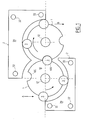
- a transfer chain essentially consisting of two stars 1 and two guides 2.
- Each star 1 is consisting of at least one plate 10 (generally two) at the periphery of the or each of which are provided imprints 100 intended to enclose the side of containers 3 so as to be able to drag them along a course which here is composed of successive arc segments.
- each plate 10 is mounted on a support 12 which is provided not only to support the tray (s) 10 but also for or drive them in rotation.
- Each guide 2 also consists of at least one plate 20 (generally two) supported by supports 22 distributed so as to ensure their stability.
- Each guide 2 is fixed and surrounds part of a star 1 at regular distance from it so to leave just enough space between them so that the receptacles 3 can there circulate.
- each guide 2 has the role of guiding the containers 3 along their route on the transfer chain, forcing them to stay in the footprints 100 of the plates 10. It will therefore be noted that the guides 2 do not have an imprint on their perimeter.
- the containers 3 therefore travel on this transfer chain driven by the stars 1 and guided by guides 2, from point A to point B. During all this route, the containers 3 can undergo various treatments, such as a filling with liquid or other, bottling or sealing, labeling, etc.
- each support 12, 22 has at least one element of support of shape and dimensions provided to be able to cooperate with an element of centering of a plate, centering element of shape and dimensions such as cooperating with a part of said or of a support element, the height of said plate on said support is determined.
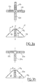
- FIGs. 2a to 2c there is shown in Figs. 2a to 2c different examples of embodiments of the invention as they have just been defined.
- Figs. 2a to 2c are visible a view of a support 12, 22 from the front and another from above and partial views showing the plate centering elements 10a, 10b and 10c.
- the support 12 consists of a single support element which is conical, or more exactly frustoconical.
- Any plate 10 which can be mounted on this support 12 has a centering element, in this case a frustoconical internal hole of the same conicity as that of the support element 12, the average diameter of which determines the positioning height of the plate 10
- the plate 10a will be positioned at the height h1 corresponding to the height on the support 12 of the diameter corresponding to the average diameter of its centering element 10 1
- the plate 10b will be positioned at the height h2 corresponding to the height on the element 12 of the diameter corresponding to the average diameter of its centering element 10 2
- the plate 10c will be positioned at the height h3 corresponding to the height on element 12 of the diameter corresponding to the average diameter of its centering element 10 3 .
- the support 12 consists of several superimposed support elements 12 1 to 12 5 which are, here, cylindrical with diameters which are such that they grow from top to bottom.
- Any plate 10 which can be mounted on this support 12 has a centering element 10 i consisting of a cylindrical hole whose diameter is that of one of the support elements 12 1 to 12 5 .
- the plate 10a will be positioned at the height h2 corresponding to the height of the support element 12 2 on the support 12, that the plate 10b will be positioned at the height h3 corresponding to the height of the support element 12 3 on the support 12 and that the plate 10c will be positioned at the height h5 corresponding to the height of the support element 12 5 on the support 12.
- a plate 10 intended to cooperate with a support element 12 i rests, by its lower face, on the base 13 i of this support element 12 i generally formed between this support element 12 i and the support element 12 i + 1 just lower. This lower face is therefore found at the height h i of the base 13 i of this support element 12 i .
- the index i is equal to one of the values 1 to n, n being the total number of support elements.
- the support 12 consists of a series of support elements of cylindrical shape 12 1 , 12 3 , 12 5 or square 12 2 , 12 4 .
- the dimensions of these support elements 12 1 to 12 5 are such that the section of an element 12 i (i equal 1 to 5) is inscribed in that of an element 12 i + 1 just lower.
- the support 12, 22 consists of a plurality of support elements 12 1 to 12 n ; 22 1 to 22 n superimposed in shape and dimensions provided to be able to cooperate respectively with a centering element 10 i of a plate 10, 20, centering element in shape and dimensions such as by cooperating with the support element , the height of said plate 10, 20 on said support 12, 22 is determined.
- the support 12, 22 consists of a number n superimposed support elements whose shape and dimensions are such that the section of a support element is registered in that of a support element just lower. It should be noted that this proposition is also true with regard to the second example of embodiment described in relation to FIG. 2b.
- FIG. 2c Also shown in this FIG. 2c, three central parts 10a, 10b and 10c of plates respectively provided with centering elements constituted by holes 10 1 , 10 2 and 10 4 of shape and dimensions corresponding to the support elements 12 1 , 12 2 and 12 4 .
- the plate 10a will be positioned at the height h1 corresponding to the height on the support 12 of the base of the support element 12 1
- the plate 10b will be positioned at the height h2 corresponding to the height on the support 12 of the support element 12 2
- the plate 10c will be positioned at the height h4 corresponding to the height on the support 12 of the support element 12 4 .
- the supports 12 shown in Figs. 2a and 2b are of symmetry of revolution about the axis xx 'of rotation of the corresponding star 1. It will be noted that the plates 10 rest on the base 13 i formed between two support elements 12 i and 12 i + 1 constituting the support 12, this base ensuring their stability.
- FIG. 3a an embodiment of a support 12 which consists of four identical branches 12a to 12d placed at 90 ° from each other with respect to the axis xx '. Each of these branches 12a, 12b, 12c and 12d has steps 12 1 to 12 9 whose distances d to the axis xx 'increase from top to bottom.
- the branch (es) would then be triangular and would therefore be generative, by rotation around the axis xx ', of said support element.
- a support 12 or 22 could include a number of branches different, for example 3, even 1 or 2, or on the contrary more.
- each branch may not extend radially from axis xx '.
- the axis xx ' is no longer an axis of rotation and therefore no longer has physical reality. he will be referred to below as the reference axis.
- FIG. 3b an embodiment of a guide support 22 which is itself made up of three identical branches 22a to 22c. Each of these branches 22a, 22b and 12c comprises steps 22 1 to 22 9 whose distances d to a reference axis xx 'increase from top to bottom. Such an embodiment could be more suitable for the support 22 of a guide 2.
- Fig. 4a we can see two plates 10h and 10b of a star 1 mounted on a rotary support 12 and embracing a container 3a of relatively large dimensions.
- the support 12 is of the type made up of branches comprising steps 12 1 to 12 11 of distances d to the axis xx 'of the support 12 growing downward forming support elements.
- the plates 10h and 10b are here respectively mounted on the steps 12 5 and 12 10 . To do this, they include centering elements 10 5 and 10 10 , for example holes, of shape and dimensions corresponding respectively to the shape and dimensions of these steps.
- Fig. 4a we can also see two plates 20h and 20b mounted on a fixed support 22 and guiding the container 3a.
- the support 22 is also of the type which comprises support elements made up of steps 22 1 to 22 12 of distances from to a vertical reference axis increasing downward.
- the plates 20h and 20b are respectively mounted on the rungs 22 3 and 22 9 and therefore comprise centering elements 20 3 and 20 9 of shape and dimensions corresponding respectively to these rungs.
- the container 3a is driven on a path of axis rr 'at distance R from the axis of rotation xx 'and embraced, by means of the notches 100, and guided by the plates 10b and 10h from star 1, on the one hand, and guided by plateaus 20b and 20h from a guide 2, on the other hand.
- Fig. 4b we can now see two other plates 10h 'and 10b' mounted on the same rotary support 12 and this time embracing a container 3b of relatively finer dimensions.
- the plates 10h 'and 10b' are respectively mounted on the steps 12 7 and 12 11 .
- the plates 10h 'and 10b' comprise centering elements 10 7 and 10 11 , in this case holes, of shape and dimensions corresponding respectively to these steps 12 7 and 12 11 .
- the centering elements 10 7 and 10 11 are of different shape and dimensions from the centering elements 10 5 and 10 10 described in relation to FIG. 4a.
- Fig. 4b we can also see two other plates 20h 'and 20b' mounted on a fixed support 22 and guiding the container 3b.
- the plates 20h 'and 20b' are respectively mounted on the rungs 22 5 and 22 10 and then comprise centering elements 20 5 and 20 10 of shape and dimensions corresponding respectively to these rungs 22 5 and 22 10 .
- the container 3b is driven on a path of axis rr 'to distance R from the axis of rotation xx 'and embraced, by means of the notches 100, and guided by trays 10b and 10h of star 1, on the one hand, and guided by trays 20b and 20h of a guide 2, on the other hand.
- the distance R between the course axis rr 'and the axis of star 1 is identical regardless of the container 3 used.
- the treatment devices filling device, bottling device, labeling device, etc.
- the container 3 is, at the distance R from the axis of rotation xx 'of the stars.
- Fig. 5a like the embodiments of FIGS. 2a to 2c and Figs. 3a and 3b, the plates 10h and 10b are placed directly in abutment on supports (two branches 12a and 12b are visible in this Fig. 5a) and the shape and dimensions of their respective centering elements 10 i are adjusted to those of the elements support 12 i on which they must respectively rest.
- This implementation generally consists, in the examples described here, of drilling holes of the desired shape and dimensions.
- the plates 10h and 10b are provided with interfaces 14h and 14b respectively which, for their part, include the centering elements 10 i , in this case holes, the shape and dimensions of which are adjusted to those of the support elements 12 i on which these plates 10h and 10b must respectively rest.
- the plates 10h and 10b can have their interiors identical t 10 holes.
- Such an arrangement can be used when the 10h and 10b trays are intended to train and / or guide containers of identical sections but of heights different.
- the 10h and 10b trays can be kept because the footprints 100h and 100b marked around their edges are always appropriate.
- the 10h, 10b trays may be at different heights depending on the container used, the interfaces 14h and 14b allow these trays 10h, 10b to be positioned at the desired height while resting on the supports 12a and 12b.
- the interfaces 14h and 14b have for example the form of disks of external diameter allowing their fixing to the plates 10h and 10b corresponding and of internal diameter corresponding to the diameters of the support elements 12 i at the desired level.
- a support 12 consisting of four branches 12a to 12d, each branch comprising notches 120 superimposed, each being provided with a groove 122 whose width is, apart from play, equal to the thickness of a plate 10 so as to be able to accommodate its inner part.
- the notches 120 are respectively generative, by rotation around the axis xx '(or of a reference axis xx' in particular in the case of a guide support), support elements.
- a plate 10 with its four notches 100 peripherals and its internal part 110.
- This internal part 110 consists of four identical sectors 110a to 110d corresponding respectively to the four branches 12a to 12d of the support 12 and cooperating with them.
- a 110 k sector is shown in close-up with a side view on the right.
- a notch 120 with a groove 122 and another notch 120 'of distance from the axis xx' greater than that of the notch 120.
- a base 124 intended to receive a tray.
- the sector 110 k consists of a clearance zone 111 produced here in the form of an arc of a circle of center on the axis xx 'and of radius r . As can be seen in FIG.
- the radius r is greater than the distance d which separates the axis xx 'from the edge of the notch 120 but is less than the distance d' which separates the axis xx 'from the edge of the notch 120' in dimension just superior.
- the sector 110 k also includes a centering zone 112 intended to be housed inside the groove 122. This centering zone 112 therefore has the same shape and the same dimension as the groove 122. It will therefore be noted that the groove 122 is a support element according to the invention and that the centering zone 112 is a centering element according to the invention.
- the sector 110 k also includes an abutment zone 113 provided for receiving a face 123 of the support 12 and thus blocking in rotation the plate 10 on the support 12.
- each branch 12a to 12d is opposite each clearance zone 111, which is made possible by the fact that the radius r is greater than the distance d , then it is rotated in the direction of the arrow A until each stop zone 113 is in abutment against each wall 123 of the branch 12a, ..., 12d corresponding. Then, we find us in the position shown in FIG. 6c with the centering zone 112 housed in the groove 122.
- At least one of the branches, in the only branch 12c, includes a locking means 125 essentially consisting of a latch 125a pivoting about an axis 125b integral with the branch 12c and being able to penetrate into a slot 115 which the panel 10 comprises.
- a locking means 125 essentially consisting of a latch 125a pivoting about an axis 125b integral with the branch 12c and being able to penetrate into a slot 115 which the panel 10 comprises.
- FIGs. 7a to 7c another embodiment of a locking means 126.
- a sector 110 k and a branch 12 with the groove 122 of a notch 120 as well as the clearance zone 111 of the sector 110 k , its centering zone 112 and its abutment zone 113.
- the means locking 126 consists of a tongue 126a which extends substantially parallel to the groove 122 so that one of the longitudinal faces constitutes the centering zone 112, the free end 126a 1 of which has a protrusion 127 provided for clamping, with the abutment zone 113, the end of the branch 12 comprising the groove 122 and, this, when the plate 10 is in position on the support 12 as shown in FIG. 7a.
- Fig. 7b for the positioning of the plate 10 on the support 12, it is positioned so that the branch 12 faces the area 110, then rotate it in the direction of arrow A until the projection 127 of the tongue 126a strikes the end of the groove 122 as this is shown in Fig. 7b.
- the tab 126a has returned to its rest position but now encloses the groove 122 as mentioned above.
- the plate 10 is then locked.
- FIG. 8a to 8c A third type of locking means is shown in Figs. 8a to 8c. Sure these Figs. 8a to 8c, we can see a support 12 made up of three branches 12a, 12b and 12c to serve as support for 10h and 10b trays which we do not see on the Figs. 8b and 8c, as the internal part 110. We also see the groove bottoms 122 a notch 120 and a centering element constituted here by a hole 111, by example of rectangular shape.
- a cam 17 with an axis parallel to the support 12 and extending over its entire height has grooves 170 corresponding bi-unequivocally to the grooves 122.
- a control member 171 placed at the end upper of cam 17 allows it to rotate around its axis.
- the cam 17 provided to cooperate with an element clamping 117, in this case an edge of the hole 111 but which could be the edge of a another hole drilled for this purpose, so that in the locked position (Fig. 8b), said plate 10 is clamped and immobilized against said support 12 (in this case, the face 112 of hole 111 is clamped against the groove bottom 122) and that outside this position (see Fig. 8c), said plate 10 is free to move and can be released from said support 12.
- an element clamping 117 in this case an edge of the hole 111 but which could be the edge of a another hole drilled for this purpose
Landscapes
- Engineering & Computer Science (AREA)
- Mechanical Engineering (AREA)
- Filling Of Jars Or Cans And Processes For Cleaning And Sealing Jars (AREA)
Applications Claiming Priority (2)
| Application Number | Priority Date | Filing Date | Title |
|---|---|---|---|
| FR0203801A FR2837786B1 (fr) | 2002-03-26 | 2002-03-26 | Ensemble outillage-support d'outillage d'une machine de conditionnement de recipients |
| FR0203801 | 2002-03-26 |
Publications (1)
| Publication Number | Publication Date |
|---|---|
| EP1352872A1 true EP1352872A1 (de) | 2003-10-15 |
Family
ID=27839225
Family Applications (1)
| Application Number | Title | Priority Date | Filing Date |
|---|---|---|---|
| EP03290746A Withdrawn EP1352872A1 (de) | 2002-03-26 | 2003-03-25 | Einheit aus Arbeitsgerät und Arbeitsgerätsträger in einer Behälterverpackungsmaschine |
Country Status (2)
| Country | Link |
|---|---|
| EP (1) | EP1352872A1 (de) |
| FR (1) | FR2837786B1 (de) |
Cited By (3)
| Publication number | Priority date | Publication date | Assignee | Title |
|---|---|---|---|---|
| FR2913964A1 (fr) * | 2007-03-23 | 2008-09-26 | Faber Soc Par Actions Simplifi | Dispositif de solidarisation d'au moins un element d'outillage de transfert, etoile, guide entree/sortie et element formant cavite correspondants. |
| WO2014161643A1 (de) * | 2013-04-03 | 2014-10-09 | Khs Gmbh | Transportvorrichtung für behälterbehandlungsmaschinen |
| WO2017089188A3 (de) * | 2015-11-25 | 2017-08-17 | Esomatec Gmbh | Vorrichtung und verfahren zum vereinzeln und/oder prüfen von behältern |
Families Citing this family (1)
| Publication number | Priority date | Publication date | Assignee | Title |
|---|---|---|---|---|
| CN104555231B (zh) * | 2015-01-14 | 2016-06-22 | 天津市华帅制药机械有限公司 | 垂直输送灌装后玻璃输液瓶的输送机设备 |
Citations (6)
| Publication number | Priority date | Publication date | Assignee | Title |
|---|---|---|---|---|
| DE572418C (de) * | 1932-03-20 | 1933-03-16 | Enzinger Union Werke Ag | Antriebsvorrichtung von Sternraedern an Flaschenbehandlungsmaschinen |
| EP0629569A1 (de) * | 1993-05-19 | 1994-12-21 | SASIB BEVERAGE S.p.A. | Sternrad mit Justiervorrichtung für unterschiedlich geformte Behälter |
| US5533608A (en) | 1994-11-03 | 1996-07-09 | Aluminum Company Of America | Quick-change center star assembly for a capping machine |
| US5689932A (en) * | 1996-05-13 | 1997-11-25 | Fci, Inc. | Quick change method and apparatus for filling and capping machines |
| FR2749285A1 (fr) * | 1996-05-28 | 1997-12-05 | Serac Group | Dispositif rotatif de convoyage et recipients |
| US5784857A (en) * | 1996-05-31 | 1998-07-28 | Riverwood International Corporation | Self- locating star wheel system for a packaging machine |
-
2002
- 2002-03-26 FR FR0203801A patent/FR2837786B1/fr not_active Expired - Fee Related
-
2003
- 2003-03-25 EP EP03290746A patent/EP1352872A1/de not_active Withdrawn
Patent Citations (6)
| Publication number | Priority date | Publication date | Assignee | Title |
|---|---|---|---|---|
| DE572418C (de) * | 1932-03-20 | 1933-03-16 | Enzinger Union Werke Ag | Antriebsvorrichtung von Sternraedern an Flaschenbehandlungsmaschinen |
| EP0629569A1 (de) * | 1993-05-19 | 1994-12-21 | SASIB BEVERAGE S.p.A. | Sternrad mit Justiervorrichtung für unterschiedlich geformte Behälter |
| US5533608A (en) | 1994-11-03 | 1996-07-09 | Aluminum Company Of America | Quick-change center star assembly for a capping machine |
| US5689932A (en) * | 1996-05-13 | 1997-11-25 | Fci, Inc. | Quick change method and apparatus for filling and capping machines |
| FR2749285A1 (fr) * | 1996-05-28 | 1997-12-05 | Serac Group | Dispositif rotatif de convoyage et recipients |
| US5784857A (en) * | 1996-05-31 | 1998-07-28 | Riverwood International Corporation | Self- locating star wheel system for a packaging machine |
Cited By (4)
| Publication number | Priority date | Publication date | Assignee | Title |
|---|---|---|---|---|
| FR2913964A1 (fr) * | 2007-03-23 | 2008-09-26 | Faber Soc Par Actions Simplifi | Dispositif de solidarisation d'au moins un element d'outillage de transfert, etoile, guide entree/sortie et element formant cavite correspondants. |
| WO2014161643A1 (de) * | 2013-04-03 | 2014-10-09 | Khs Gmbh | Transportvorrichtung für behälterbehandlungsmaschinen |
| US9694988B2 (en) | 2013-04-03 | 2017-07-04 | Khs Gmbh | Conveyor system for container processing machines |
| WO2017089188A3 (de) * | 2015-11-25 | 2017-08-17 | Esomatec Gmbh | Vorrichtung und verfahren zum vereinzeln und/oder prüfen von behältern |
Also Published As
| Publication number | Publication date |
|---|---|
| FR2837786B1 (fr) | 2004-07-16 |
| FR2837786A1 (fr) | 2003-10-03 |
Similar Documents
| Publication | Publication Date | Title |
|---|---|---|
| FR2803244A1 (fr) | Support de rouleau de support d'information a cremaillere | |
| FR2805252A1 (fr) | Dispositif de transfert de recipients comportant une roue de guidage a geometrie variable | |
| EP3448197A1 (de) | Lager- und ausstellvorrichtung zum lagern und ausstellen einer vielzahl von länglichen handwerkzeugen | |
| FR2749285A1 (fr) | Dispositif rotatif de convoyage et recipients | |
| FR3103183A1 (fr) | Etoile pour une machine de conditionnement rotative | |
| EP1352872A1 (de) | Einheit aus Arbeitsgerät und Arbeitsgerätsträger in einer Behälterverpackungsmaschine | |
| EP1930093A1 (de) | Gerät zur Kontrolle der Karosserieverformungen eines Kraftfahrzeugs und entsprechender Werkstattwagen | |
| EP2200534B1 (de) | Düppelaufbereitungsmaschine | |
| EP1756830B2 (de) | Hülle für schräg gelagerte digitalplatten | |
| EP2379430A1 (de) | Phiolenfördereinrichtung | |
| EP1253978A2 (de) | Küvetten, automatisches analysegerät, das solche küvetten verwendet, sowie vorrichtung und verfahren zum übertragen solcher küvetten | |
| EP2924518A1 (de) | Uhrtürmchen zum Durchführen von Operationen an Uhrwerken | |
| EP2754586B1 (de) | Verstauungselement für den Stauraum eines Reserverads eines Kraftfahrzeugs | |
| EP0287438A1 (de) | Vorrichtung zum Injizieren von Schutzgas in Kunststoffbecher, insbesondere für Lebensmittel | |
| EP2340742A1 (de) | Verkaufsständer zum Präsentieren und/oder Ordnen | |
| EP1010842A1 (de) | Stützfussvorrichtung für Stange oder Pfosten, insbesondere für Laube- oder Paneelunterstützung und Schliessverfahren dafür | |
| EP4035976B1 (de) | Multifunktionaler fahrradgepäckträger | |
| EP1694172B1 (de) | Vorrichtung zur darbietung von gegenständen | |
| EP0192571A2 (de) | Probenhalter für Zentrifuge und Verfahren zu seiner Herstellung | |
| FR2758298A1 (fr) | Porte-gobelets, particulierement pour vehicule automobile | |
| FR3033345A1 (fr) | Bac, ensemble comprenant un tel bac et procede d'installation d'un tel ensemble sur une paroi | |
| FR3133103A1 (fr) | Dispositif de fixation ameliore d’un emballage de transport de matieres radioactives ou de son chassis de support, sur un systeme de transport | |
| FR3130522A1 (fr) | Porte-valise | |
| EP1535501A1 (de) | Wendevorrichtung für elektronische bauteile | |
| EP0545837A1 (de) | Markierungentragender Vorrichtung zum Bezeichnen von Leitern, und sein Herstellungsverfahren |
Legal Events
| Date | Code | Title | Description |
|---|---|---|---|
| PUAI | Public reference made under article 153(3) epc to a published international application that has entered the european phase |
Free format text: ORIGINAL CODE: 0009012 |
|
| AK | Designated contracting states |
Kind code of ref document: A1 Designated state(s): AT BE BG CH CY CZ DE DK EE ES FI FR GB GR HU IE IT LI LU MC NL PT RO SE SI SK TR |
|
| AX | Request for extension of the european patent |
Extension state: AL LT LV MK |
|
| AKX | Designation fees paid | ||
| REG | Reference to a national code |
Ref country code: DE Ref legal event code: 8566 |
|
| STAA | Information on the status of an ep patent application or granted ep patent |
Free format text: STATUS: THE APPLICATION IS DEEMED TO BE WITHDRAWN |
|
| 18D | Application deemed to be withdrawn |
Effective date: 20040416 |