EP1352996A2 - Vorrichtung zum Herstellen von Mehrkomponentenfäden in Rotorspinnmaschinen und Sensor für Spinnmaschinen zur Mehrkomponentenfäden-Herstellung - Google Patents
Vorrichtung zum Herstellen von Mehrkomponentenfäden in Rotorspinnmaschinen und Sensor für Spinnmaschinen zur Mehrkomponentenfäden-Herstellung Download PDFInfo
- Publication number
- EP1352996A2 EP1352996A2 EP03466009A EP03466009A EP1352996A2 EP 1352996 A2 EP1352996 A2 EP 1352996A2 EP 03466009 A EP03466009 A EP 03466009A EP 03466009 A EP03466009 A EP 03466009A EP 1352996 A2 EP1352996 A2 EP 1352996A2
- Authority
- EP
- European Patent Office
- Prior art keywords
- component
- sensor
- rotor
- yarn
- continuous
- Prior art date
- Legal status (The legal status is an assumption and is not a legal conclusion. Google has not performed a legal analysis and makes no representation as to the accuracy of the status listed.)
- Withdrawn
Links
Images


Classifications
-
- D—TEXTILES; PAPER
- D01—NATURAL OR MAN-MADE THREADS OR FIBRES; SPINNING
- D01H—SPINNING OR TWISTING
- D01H4/00—Open-end spinning machines or arrangements for imparting twist to independently moving fibres separated from slivers; Piecing arrangements therefor; Covering endless core threads with fibres by open-end spinning techniques
- D01H4/04—Open-end spinning machines or arrangements for imparting twist to independently moving fibres separated from slivers; Piecing arrangements therefor; Covering endless core threads with fibres by open-end spinning techniques imparting twist by contact of fibres with a running surface
- D01H4/08—Rotor spinning, i.e. the running surface being provided by a rotor
- D01H4/10—Rotors
-
- D—TEXTILES; PAPER
- D01—NATURAL OR MAN-MADE THREADS OR FIBRES; SPINNING
- D01H—SPINNING OR TWISTING
- D01H1/00—Spinning or twisting machines in which the product is wound-up continuously
- D01H1/14—Details
- D01H1/16—Framework; Casings; Coverings ; Removal of heat; Means for generating overpressure of air against infiltration of dust; Ducts for electric cables
-
- D—TEXTILES; PAPER
- D01—NATURAL OR MAN-MADE THREADS OR FIBRES; SPINNING
- D01H—SPINNING OR TWISTING
- D01H4/00—Open-end spinning machines or arrangements for imparting twist to independently moving fibres separated from slivers; Piecing arrangements therefor; Covering endless core threads with fibres by open-end spinning techniques
Definitions
- the invention relates to the device for multi-component yarn production comprising a continuous component and a component spun in the rotor of a rotor spinning machine from singled-out fibres, whose operating unit contains a device for feeding the sliver, its singling out into singled-out fibres and feeding the singled-out fibres into the spinning rotor where they are processed into a spun component which, having been produced, combines in the rotor with a continuous component supplied to the rotor with the device for supplying continuous component, to produce a multi-component fibre; in order to take it out of the rotor, the operating unit is fitted with a draw-off device of the multi-component yarn and winding device, while there is a sensor of the continuous component inserted in the path of the continuous component and at least one sensor inserted in the path of the multi-component yarn monitoring a presence, movement or quality of the multi-component yarn.
- the invention further relates to the sensor for rotor spinning machines producing multi-component yarn, which contains a continuous component, supplied to the rotor and a component spun in the rotor from singled-out fibres on the rotor spinning machine.
- the known device for the multi-component yarn production comprising a continuous component and a component spun in the rotor of a rotor spinning machine from singled-out fibres, e.g. in accordance with CZ 281809, contains a sensor for presence of the multi-component yarn placed in between the spinning unit and the winding device of the multi-component yarn and a sensor for presence of the continuous component placed between the unwinding device of the continuous component and a spinning unit where the continuous component is supplied.
- Both the mentioned sensors are connected to the control unit which has still more sensors connected to it as well as control means of the relevant operating unit of the rotor spinning machine.
- the aim of the invention is to produce a device for multi-component yarn production comprising a continuous component and a component spun in the rotor of a rotor spinning machine from singled-out fibres, which would allow for easier placing of the sensor of the continuous component on the operating unit of the machine, and make a sensor that would enable such placing, while this would also result in reducing the cost of production of such a sensor.
- the aim of the invention is achieved by providing a device for multi-component yarn production comprising a continuous component and a component spun in the rotor of a rotor spinning machine from singled-out fibres, whose principle consists in that the part of the path of the continuous component in the area of the sensor of the multi-component yarn is situated next to the path of the multi-component yarn.
- the close distance of the path of the continuous component in the area of the sensor of the multi-component yarn also allows for installation of the sensor of the continuous component in the same area, so that it is not needed to carry out complicated modifications to the operating unit that would enable situating of the sensor of the continuous component.
- part of the path of the continuous component, situated next to the path of the multi-component yarn is parallel to the part of the path of the multi-component yarn in this area, which again significantly facilitates the placement of the continuous component sensor on the operating unit.
- the sensor of the continuous component may also be placed next to the sensor of the multi-component yarn or the sensors may be placed one over the other, depending on the current need.
- the saving of space is achieved by placing the both of sensors on one holder, or even better, by their integration to one case.
- the principle of the sensor for the rotor spinning machines producing multi-component yarn comprising a continuous component fed into the rotor and a component spun in the rotor from singled-out fibres consists in that it contains means for monitoring of the multi-component yarn produced in the rotor, and means for monitoring of the continuous component supplied into the rotor, placed in a single common case.
- a sensor is created able to transmit information both about the multi-component yarn, e.g. about its presence at the monitoring area, its quality or presence of foreign particles in the multi-component yarn, as well as the information about the continuous component, namely about its presence.
- These sensors are connected to the evaluation circuits to evaluate the information that may be common for the sensors and may also be placed in the sensor case.
- the embodiment requiring less space for installation has one common path in the sensor case available for passing of the multi-component yarn and of the continuous component.
- the means for monitoring of the multi-component yarn and the means for monitoring of the continuous component are placed along the path of the multi-component yarn or of the continuous component, or the means are placed in a common path one over the other, which further simplifies the construction and reduces the space required for their installation.
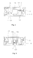
- FIG. 1 shows the operating unit of the machine with two sensors placed next to each other
- Fig. 2 shows two sensors placed one over the other
- Fig. 3 shows the embodiment of sensor containing the means in one case for monitoring of the multi-component yarn produced in the rotor, and the means for monitoring of the continuous component fed into the rotor and the means for evaluating information at least about multi-component yarn and continuous component.
- the rotor spinning machine for multi-component yarn production containing the continuous component, particularly the elastic component, has plurality of next to each other arranged operating units, each of them comprises a container 1 for the sliver 2 , from which is supplied the sliver 2 into the well-known not represented singling-out device , from which the singled-out fibres 21 are led into the spinning rotor 3 , where at the same time the continuous component 4 is supplied from the winding-off device 41 of the continuous component.
- multi-component yarn 5 comprising continuous component 4 and component spun in the rotor 3 from singled out fibres 21 .
- Multi-component yarn 5 is drawn off by draw-off device 6 a well-known manner from the rotor 3 and wound onto a bobbin 71 by a well-known winding device 7 .
- a sensor 8 of the multi-component yarn is inserted, which is according of embodiment as shown in Fig. 1 mounted on the holder 9 .
- the holder 9 is mounted on the frame or another suitable part of the machine in well-known not represented manner.
- the path of the continuous component 4 is situated in the area of the sensor 8 of the multi-component yarn, next to the path of the multi-component yarn 5 and the sensor 10 of the continuous component is inserted in the path in this area, which in the shown embodiment is mounted on the common holder 9 along with the sensor 8 of the multi-component yarn.
- the sensor 8 of the multi-component yarn comprises an aperture 81 for passing of the multi-component yarn 5 , around which there are elements appropriately positioned for monitoring presence and/or movement and/or quality of the multi-component yarn 5 and/or presence of foreign fibres in the multi-component yarn 5 .
- the sensor 10 of the continuous component comprises an aperture 101 for passing of the continuous component 4 , around which there are elements appropriately positioned for monitoring presence and/or movement of the continuous component 4 .
- the sensor 8 of the multi-component yarn and the sensor 10 of the continuous component may, if needed, contain other means for monitoring further properties of the multi-component yarn 5 or of the continuous component 4 , while in the shown embodiment the part of the path of the continuous component 4 passes through the sensor 10 of the continuous component parallel with the path of the multi-component yarn 5 near the sensor 8 of the multi-component yarn.
- the path of the continuous component 4 is deviated from its normal course by means of the known yarn guides 42 , 43 thus being situated next to the path of the multi-component yarn 5 .
- Yarn guides 42 , 43 may be fixed or rotation type as needed.
- the sensors 8 of the multi-component yarn and sensor 10 of the continuous component are in the known way connected with the evaluation circuits 11, which are advantageously common to the both sensors, usually placed on the corresponding operating unit of the machine.
- Fig. 2 is the sensor 10 of the continuous component placed over the sensor 8 of the multi-component yarn on a common holder 9 , while each of the sensors 8 , 10 is fitted with a separate aperture 81 , 101 for the passing of the continuous component 4 or of the multi-component yarn 5 .
- the sensors 8 of the multi-component yarn and the sensor 10 of the continuous component in embodiment according to Fig. 3 are integrated in a common case 12 , where also their evaluation circuits are placed 11 including the processors needed for their evaluation, which may however be placed outside of the case 12 if needed, e.g. inside the evaluation unit of the operating unit or in the evaluation unit of a machine section.
- Each of the sensors 8 , 10 is fitted with its own opening 81 , 101 for the passing of the continuous component 4 or of the multi-component yarn 5 .
- the integrated sensor 13 for rotor spinning machines producing the multi-component yarn 5 containing the continuous component 4 supplied to the rotor 3 and the component spun in rotor 3 from singled-out fibres.
- the integrated sensor 13 contains in one case 12 the means for monitoring of the multi-component yarn 5 and of the continuous component 4 .
- Fig. 4 is in the integrated sensor 13 created an aperture 131 for passing of the multi-component yarn 5 , which has a sensor 132 of the multi-component yarn 5 assigned, and an aperture 133 for passing of the continuous component 4 , which has a sensor 134 of the continuous component 4 assigned.
- evaluation circuits 135 including at least one microprocessor.
- the sensor 132 of the multi-component yarn and the sensor 134 of the continuous component are made to one of the known well-suited principle of monitoring the properties and/or movement and/or presence of yarn and therefore may be of capacity or optical kind.
- For the optical monitoring it is possible to use optical sensors with a row optical element, e.g. CCD or CMOS.
- row optical element in the optical sensor allows for creating an integrated sensor 130 , shown in Fig. 5, where there is one aperture 1301 created for passing of the multi-component yarn 5 and continuous component 4 , which has a row optical sensor 1302 using for monitoring of the multi-component yarn 5 and the continuous component 4 .
Landscapes
- Engineering & Computer Science (AREA)
- Mechanical Engineering (AREA)
- Textile Engineering (AREA)
- Spinning Or Twisting Of Yarns (AREA)
- Yarns And Mechanical Finishing Of Yarns Or Ropes (AREA)
Applications Claiming Priority (2)
| Application Number | Priority Date | Filing Date | Title |
|---|---|---|---|
| CZ20021258 | 2002-04-10 | ||
| CZ20021258A CZ292980B6 (cs) | 2002-04-10 | 2002-04-10 | Zařízení pro výrobu složkové příze a zařízení pro sledování alespoň jednoho parametru vypřádané složkové příze |
Publications (2)
| Publication Number | Publication Date |
|---|---|
| EP1352996A2 true EP1352996A2 (de) | 2003-10-15 |
| EP1352996A3 EP1352996A3 (de) | 2004-02-04 |
Family
ID=28050596
Family Applications (1)
| Application Number | Title | Priority Date | Filing Date |
|---|---|---|---|
| EP03466009A Withdrawn EP1352996A3 (de) | 2002-04-10 | 2003-04-09 | Vorrichtung zum Herstellen von Mehrkomponentenfäden in Rotorspinnmaschinen und Sensor für Spinnmaschinen zur Mehrkomponentenfäden-Herstellung |
Country Status (2)
| Country | Link |
|---|---|
| EP (1) | EP1352996A3 (de) |
| CZ (1) | CZ292980B6 (de) |
Cited By (3)
| Publication number | Priority date | Publication date | Assignee | Title |
|---|---|---|---|---|
| CN103938322A (zh) * | 2014-04-25 | 2014-07-23 | 嘉兴学院 | 一种转杯纺混色成纱方法及装置与产品 |
| CN111155208A (zh) * | 2020-03-03 | 2020-05-15 | 江南大学 | 一种新的纺纱装置及其生产方法 |
| CN111850748A (zh) * | 2020-07-21 | 2020-10-30 | 江南大学 | 一种长丝短纤气流纺复合纱生产装置与方法 |
Families Citing this family (2)
| Publication number | Priority date | Publication date | Assignee | Title |
|---|---|---|---|---|
| CZ301816B6 (cs) * | 2005-09-26 | 2010-06-30 | Rieter Cz S.R.O. | Zarízení k odvíjení lineárního textilního materiálu pri výrobe složkové príze na rotorovém doprádacím stroji |
| CZ201888A3 (cs) | 2018-02-22 | 2019-09-04 | Rieter Cz S.R.O. | Způsob řízení optického prvku na pracovním místě textilního stroje, zejména stroje vyrábějícího přízi a textilní stroj |
Family Cites Families (3)
| Publication number | Priority date | Publication date | Assignee | Title |
|---|---|---|---|---|
| DE3537195A1 (de) * | 1985-10-18 | 1987-04-23 | Zinser Textilmaschinen Gmbh | Spinnmaschine |
| SK278624B6 (en) * | 1992-07-07 | 1997-11-05 | Miloslav Rencin | Device for producing multicomponent yarn |
| CZ286113B6 (cs) * | 1998-01-14 | 2000-01-12 | Rieter Elitex A. S. | Způsob zjišťování tloušťky a/nebo homogenity pohybujícího se lineárního útvaru a zařízení k provádění tohoto způsobu |
-
2002
- 2002-04-10 CZ CZ20021258A patent/CZ292980B6/cs not_active IP Right Cessation
-
2003
- 2003-04-09 EP EP03466009A patent/EP1352996A3/de not_active Withdrawn
Cited By (3)
| Publication number | Priority date | Publication date | Assignee | Title |
|---|---|---|---|---|
| CN103938322A (zh) * | 2014-04-25 | 2014-07-23 | 嘉兴学院 | 一种转杯纺混色成纱方法及装置与产品 |
| CN111155208A (zh) * | 2020-03-03 | 2020-05-15 | 江南大学 | 一种新的纺纱装置及其生产方法 |
| CN111850748A (zh) * | 2020-07-21 | 2020-10-30 | 江南大学 | 一种长丝短纤气流纺复合纱生产装置与方法 |
Also Published As
| Publication number | Publication date |
|---|---|
| EP1352996A3 (de) | 2004-02-04 |
| CZ292980B6 (cs) | 2004-01-14 |
| CZ20021258A3 (cs) | 2003-11-12 |
Similar Documents
| Publication | Publication Date | Title |
|---|---|---|
| CN101849049B (zh) | 用于操作制造交叉卷绕筒子的纺织机械的工位的方法 | |
| TR199800625T2 (xx) | Elektronik kumandaya sahip iplik besleyici cihaz. | |
| PL314229A1 (en) | Spinning frame for twisting two fibres into a single strand | |
| CN105274665B (zh) | 生产交叉卷绕筒子的半自动纺织机 | |
| EP1352996A2 (de) | Vorrichtung zum Herstellen von Mehrkomponentenfäden in Rotorspinnmaschinen und Sensor für Spinnmaschinen zur Mehrkomponentenfäden-Herstellung | |
| CN205990485U (zh) | 用于确定由运行纱线构成的纱线气圈的直径的装置 | |
| US6679043B2 (en) | Spinning machine | |
| CN102560755B (zh) | 使用了空气纺纱装置的纺纱方法及空气纺纱装置 | |
| CN106429636B (zh) | 纱线监视装置和纱线卷绕机 | |
| EP1676943B1 (de) | Verfahren und Vorrichtung zur Belieferung einer Textilmaschine mit einem Garn | |
| JP4908015B2 (ja) | たとえばフラット・カード、ローラ・カード、練篠フレームなどの紡績用前処理機において少なくとも一本のスライバを監視する装置 | |
| ITMI942228A1 (it) | Dispositivo per paraffinare | |
| JP4819227B2 (ja) | 繊維スライバの運動および/または存在を検出する装置 | |
| US7392648B2 (en) | Rotor Spinning machine | |
| JP2000073237A (ja) | 単錘駆動型繊維機械 | |
| EP3124658B1 (de) | Streckvorrichtung für spinnrahmen | |
| CN108977945A (zh) | 辊单元、牵伸装置以及纺纱机械 | |
| CZ299647B6 (cs) | Zarízení pro bezdotykové merení lineárního textilního útvaru, napr. príze, niti, textilního vlákna,pramene vláken | |
| CZ306035B6 (cs) | Způsob navíjení příze na křížovou cívku na pracovním místě rotorového dopřádacího stroje a zařízení k provádění způsobu | |
| US5261220A (en) | Spinning machine having a plurality of spinning stations arranged next to one another | |
| CN105525396B (zh) | 纱线卷绕机 | |
| US5325658A (en) | Spinning machine with false-twisting devices | |
| CN102471952B (zh) | 用于制造包芯纱的设备及方法 | |
| ITMI970837A1 (it) | Filatoio con uno stiratoio a piu' stadi,presentante all'uscita un cilindro aspirante,come pure procedimento per la realizzazione | |
| CN206089934U (zh) | 纱线监视装置以及纱线卷绕机 |
Legal Events
| Date | Code | Title | Description |
|---|---|---|---|
| PUAI | Public reference made under article 153(3) epc to a published international application that has entered the european phase |
Free format text: ORIGINAL CODE: 0009012 |
|
| AK | Designated contracting states |
Kind code of ref document: A2 Designated state(s): AT BE BG CH CY CZ DE DK EE ES FI FR GB GR HU IE IT LI LU MC NL PT RO SE SI SK TR |
|
| AX | Request for extension of the european patent |
Extension state: AL LT LV MK |
|
| PUAL | Search report despatched |
Free format text: ORIGINAL CODE: 0009013 |
|
| AK | Designated contracting states |
Kind code of ref document: A3 Designated state(s): AT BE BG CH CY CZ DE DK EE ES FI FR GB GR HU IE IT LI LU MC NL PT RO SE SI SK TR |
|
| AX | Request for extension of the european patent |
Extension state: AL LT LV MK |
|
| RIC1 | Information provided on ipc code assigned before grant |
Ipc: 7D 01H 13/16 B Ipc: 7D 01H 1/16 B Ipc: 7D 01H 4/00 A |
|
| 17P | Request for examination filed |
Effective date: 20040720 |
|
| AKX | Designation fees paid |
Designated state(s): BE CH DE IT LI |
|
| 17Q | First examination report despatched |
Effective date: 20071123 |
|
| GRAP | Despatch of communication of intention to grant a patent |
Free format text: ORIGINAL CODE: EPIDOSNIGR1 |
|
| STAA | Information on the status of an ep patent application or granted ep patent |
Free format text: STATUS: THE APPLICATION IS DEEMED TO BE WITHDRAWN |
|
| 18D | Application deemed to be withdrawn |
Effective date: 20090710 |