EP1352998A2 - Zuführwalze und Auflösevorrichtung für eine Spinnvorrichtung - Google Patents
Zuführwalze und Auflösevorrichtung für eine Spinnvorrichtung Download PDFInfo
- Publication number
- EP1352998A2 EP1352998A2 EP03000989A EP03000989A EP1352998A2 EP 1352998 A2 EP1352998 A2 EP 1352998A2 EP 03000989 A EP03000989 A EP 03000989A EP 03000989 A EP03000989 A EP 03000989A EP 1352998 A2 EP1352998 A2 EP 1352998A2
- Authority
- EP
- European Patent Office
- Prior art keywords
- roller
- feed
- spinning
- opening
- dissolving
- Prior art date
- Legal status (The legal status is an assumption and is not a legal conclusion. Google has not performed a legal analysis and makes no representation as to the accuracy of the status listed.)
- Withdrawn
Links
Images


Classifications
-
- D—TEXTILES; PAPER
- D01—NATURAL OR MAN-MADE THREADS OR FIBRES; SPINNING
- D01H—SPINNING OR TWISTING
- D01H4/00—Open-end spinning machines or arrangements for imparting twist to independently moving fibres separated from slivers; Piecing arrangements therefor; Covering endless core threads with fibres by open-end spinning techniques
- D01H4/30—Arrangements for separating slivers into fibres; Orienting or straightening fibres, e.g. using guide-rolls
- D01H4/32—Arrangements for separating slivers into fibres; Orienting or straightening fibres, e.g. using guide-rolls using opening rollers
Definitions
- the invention relates to a feed roller for a spinning device with a Work area for providing a first spinning material for a spinning element and an opening device for a spinning device with a in a housing rotatably mounted opening roller and a feed device for feeding a sliver to the opening roller.
- a feeding and opening device for a spinning device (DE 39 10 292 A1) is a sliver for separating the fibers pulled through a feed opening by means of a feed shaft and to a The opening roller transported the opening device. Through a set the fibers from the fiber sliver are separated on the opening roller carried by the opening roller. The opening roller closes in the direction of rotation a dirt separation opening at the feed opening, through which in the sliver contained impurities are excreted. The fibers the opening roller itself continues in the circumferential direction and through a further opening in the housing of the opening device sucked into a fiber feed channel.
- a feeding and dissolving device branches in the circumferential direction behind a main fiber feed channel an auxiliary fiber feed channel, which also fibers from the opening roller transported to a spinning rotor.
- the auxiliary fiber feed channel opens into in this case, however, not in the main fiber feed channel, but is separated from this led directly to the spinning rotor, so that the through this auxiliary fiber feed channel fibers separately from the main fiber feed channel be fed into the rotor.
- a feed roller for a spinning device has one first work area for providing a first spinning material and one second work area for providing a second spinning material on.
- a spinning device is usually a spinning station of an open-end spinning device, such as a rotor spinning station, a friction spinning station, a vortex spinning station or the like.
- a to be provided Spinning material is regularly the individual fibers from one Sliver, a sliver, a yarn or the like.
- the feed roller is thereby rotatably mounted and is preferably via a drive, such as a belt, an electric motor, or the like.
- the spinning element is usually a spinning rotor in a rotor spinning machine, a vortex nozzle, in a vortex spinning machine, a swirl element in a friction spinning machine or the like.
- the axially staggered arrangement of the two work areas makes one spatial decoupling of the two work areas achieved.
- the axial width of the two working areas can be the same, for example Equipping the work areas can be chosen so that the work areas or their working elements do not have to be developed separately and can be produced inexpensively. Both areas of work are advantageous separated from each other by a separating element so that providing of the two spinning materials independently and for example without Mixing takes place within the work areas.
- the provision can be made by different diameters of the work areas of the first and the second spinning material independently of each other optimize.
- both work areas with sets equipped for separating fibers from a sliver so be different relative speeds at different diameters of the scope of the work area with respect to the sliver reached.
- different types of slivers each process optimized.
- can when loading the feed roller with two different sets in the first work area Chemical fiber tape are processed while in the second work area Cotton sliver is processed.
- the sets are for processing different materials optimized. Or it can change the game the changeover time on a spinning machine to replace the clothing set on an opening roller, since there are already two work areas can be provided with different sets and at Batch change only the work area is to be changed.
- the second work area is used as a feed roller for feeding an elongated trained second spinning material, e.g. for one Friction spinning device the core yarn or the soul and those to be spun Fibers are provided simultaneously via only one feed roller.
- an elongated trained second spinning material e.g. for one Friction spinning device the core yarn or the soul and those to be spun Fibers are provided simultaneously via only one feed roller.
- the opening device for a spinning device a first and a second feed device for independent feeding a first and second fiber sliver rotatable into a single or two stored opening rollers.
- a first and a second opening roller By the first and / or second opening roller the fibers from the first and second fiber sliver are dissolved and provided for a spinning element.
- a Spinning element a spinning rotor, a vortex nozzle, a friction spinning element or similar.
- Operation of the first and second feeders for feeding a first and a second sliver for example be carried out as follows: Both feeders work simultaneously and feed two identical or different slivers; one Feeder worked continuously and the other with time varying Indent; alternately either one or the other feed device becomes operated (for example, the feeder at a lot change). For the production of blended yarn different sliver materials separated on the feeders moved in. For the production of fancy yarn (thickness variation, Color variation etc.) becomes a feeding device with varying speed operated (artificial moiree effect).
- two opening rollers are used, they are advantageously replaced by one shared opening roller drive means driven so that none separate drive devices are required. These are advantageous arranged on a common shaft.
- the opening rollers are different fittings or the same Have clothing facilities.
- the fittings are advantageous exchangeably mounted on the opening roller in a conventional manner, so that they can be replaced individually or together.
- Using the same opening rollers or sets can be advantageous be formed in one piece, so that the installation and manufacturing costs reduced.
- the feed width for the sliver doubles, so that instead of a single, limited width sliver the double width of sliver to the opening roller or to both opening rollers is fed. This enables twice the throughput of fibers.
- the fiber feed process for a spinning element is separate for each feeder optimize.
- Become the feed devices are arranged offset to one another in the circumferential direction, while they are arranged at the same height in the axial direction, so the structural depth of the opening device is small in the axial direction.
- a separator is provided in the housing of the opening device, so that the fibers fed to the first and second opening rollers do not mix. It can be used in both separate housing chambers also set different pressure and flow conditions and for the fiber material used or the feed and removal geometry optimize.
- Two feed channel sections are very particularly advantageously provided, wherein one of the first and the second opening roller is assigned.
- the two feed channel sections can also be arranged so that they preferably take out the fibers that isolated from each of the feeders from their sliver were.
- the two feed channel sections are combined into one feed channel guided, the fibers mix when they are fed to the spinning element.
- the fibers from the first and second feed channel sections are particularly advantageous fed separately to the spinning element, so that the fiber feed for the spinning element can be optimized separately for each feed channel section is. Due to the spatially offset feeding of the fibers to the spinning element the fibers can be integrated from the different feed channel sections optimize into a yarn to be spun separately.
- the fibers from the first feed channel section are preferred incorporated as core fibers of the yarn to be spun, while the fibers from the second feed channel as wrapping fibers of the yarn core serve. This allows, for example, color effects between the inner and reach outer fibers, improve the yarn tensile strength, the hairiness depending on the desired quality increase or decrease or the like.
- first and second feed devices can be controlled independently of one another, for example, the supply of the first and second sliver can be switched on and off independently or their speed adjustable.
- the first and second feed device driven by a common drive device however, the first and / or the second feed device can be uncoupled or coupled from the drive element. So simplified the drive of the feed devices while switching on and off the first and / or second feed device independently of one another can be done. By switching one of the feed devices on and off For example, a fancy yarn with changing color or yarn mass produce.
- the dissolving and feeding device for a spinning device has a feed roller with a first work area which is called Opening roller is formed, and a second work area, which as Transport roller is formed. Fibers are made from the opening roller a sliver and isolated by means of the transport roller an elongated trained spinning material supplied. As above with the feed roller executed, it can be used for spinning and for example a yarn as the core material for a friction spinning device respectively.
- the opening roller device Used in a conventional opening roller device for an open-end spinning machine fiber feeding with otherwise constant operating conditions the opening roller device (constant speeds and Vacuum conditions etc.) increases, then decreases from a certain fiber throughput the quality of the dirt separation significantly. On the one hand more dirt is introduced into the fiber feed channel and on the other hand more fibers are excreted from the dirt separation channel. On the one hand, this reduces the yarn quality due to contamination and on the other hand, production efficiency is reduced by loss of fiber material through the discharge channel. Overall, the conventional opening roller device the throughput of fiber material limited and therefore also the maximum production per spinning station.
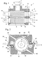
- FIG. 1 shows the opening device 1 in a partial cross-sectional view schematically.
- a housing 2 of Dissolving device 1 two opening rollers 5, 6 are rotatable on a shaft 3 stored.
- the shaft 3 is mounted on the housing 2 via a bearing housing 4 and is on a whorl 7 by a drive belt, not shown driven.
- Each opening roller 5, 6 has a separate clothing ring, which are separated from each other by a cutting disc 8.
- the cutting disc 8 interacts with the inner wall surrounding housing 2, so that the opening rollers 5, 6 in almost completely separated from each other Housing chambers are arranged. There is almost no current from Air or fiber particles between the two housing chambers of the opening rollers 5, 6 instead.
- the opening roller 5 is fed via a first sliver 9 a sliver (A) fed and the opening roller 6 is via a a second sliver feeder 10 is fed a second sliver (B).
- the Sliver lies on a sliver support 11, 12 and is transported by a first feed roller 13 or second feed roller 14.
- a spring not shown, the sliver supports 11, 12 each pressed against the feed roller 13, 14 and thereby the to be drawn Sliver clamped.
- the feed rollers 13, 14 are by a Feed shaft 15 driven, each feed roller 13, 14 on, not shown Way via an electromagnetic coupling to the feed shaft 15 is coupled.
- the fibers are separated by the opening rollers 5, 6 from the sliver feeds 9, 10 removed and through the opening roller to openings in Housing 2 transported, where it then in a first fiber feed channel 16th or a second fiber feed channel 17 are sucked in.
- the first Fiber feed channel 16 almost exclusively reach those fibers that were triggered from the sliver A, which in the first sliver feed 9 was confiscated.
- Get into the second fiber feed channel 17 the fibers of the sliver B, which is 10 is transported to the opening roller 6.
- Between the fiber ribbon feeders 9, 10 and the openings to the fiber feed channels 16, 17 is one further opening, not shown here, arranged in the housing 2, through which Dirt particles are excreted from the housing 2.
- the first and second feed rollers can be 13, 14 each separately by a coupling device to the Connect or disconnect feed shaft 15. It can also be provided be that only one of the feed rollers 13 or 14 via a coupling device is connected to the feed shaft 15.
- the feed shaft 15 can itself again through a coupling device with a main feed shaft (Not shown) connected so that the feed rollers 13, 14th together via the coupling between the feed shaft 15 and the main feed shaft be activated or deactivated.
- the opening rollers 5, 6 can each be equipped with the same set be or with different trimmings based on special fiber material are designed.
- the tooth density of the opening roller 5 can be reduced be when through the first sliver feed 8 sliver material with particularly long fibers.
- the clothing tooth density the opening roller 6 may be particularly high when by second sliver feed 10 a sliver material with a short fiber length and / or a high degree of pollution.
- FIG. 2 shows a second embodiment of a dissolving device 30
- Housing 31 of the opening device 30 is a rotatably mounted opening roller 32 arranged.
- the housing 31 are in the circumferential direction with respect to Opening roller at two different positions a first sliver feed 33 and a second sliver feeder 34 are arranged.
- a first sliver feed 33 becomes a sliver (A) between a sliver support 35 and a first feed roller 36 is clamped.
- a sliver (B) between a sliver support 37 and a second feed roller 38 clamped.
- the first and second feed rollers 36, 38 can independently be driven, be driven together, one or both of the feed rollers via a clutch mechanism from the drive can be uncoupled, and furthermore both feed rollers 36, 38 can be used constant or adjustable feed speed.
- the Sliver supports 35, 36 are in the direction by a pressure spring 39, 40 the feed rollers 36, 38 pressed, so that a clamping of the slivers A, B takes place and the sliver A, B by rotating the feed roller 36, 38 transported in the direction of the opening roller 32 and, if necessary by reverse rotation of the feed roller 36, 38 from the opening roller 32 withdrawn.
- the first sliver intake follows 33 a first dirt separation channel 41 through which due to the centrifugal force excretes impurities of the first sliver A downwards become.
- the opening roller 32 follows in the direction of rotation the first dirt separation channel 41 a first fiber feed channel 42, through which the fibers separated from the first sliver A are sucked off and be directed to the spinning element.
- the opening roller follows in the direction of rotation after the second sliver feed 34 a second dirt separation channel 43. This is with respect to the opening roller 32 designed as a tangential channel.
- a first opening 45 air enters the dirt separation channel 43, which passes through a second Opening 46 is sucked off with the entrained impurities.
- the Dirt particles are detected and removed from the opening roller. The dirt particles get into the second dirt separation channel essentially by centrifugal force 43, so that no fibers through the second dirt separation channel 43 are sucked off by the opening roller 32.
- I denotes the first work area, which extends along the circumference of the opening roller 32 from the first sliver feed 33 extends to the first fiber feed channel 42
- II the second Working area extending along the circumference of the opening roller from the second Sliver feed 34 extends to the second fiber feed channel 44.
- FIGS. 3A and 3B schematically represent the course of the fiber feed channels from the opening roller 32 or 5 and 6 to a spinning element 50.
- the fiber feed channels 44 and 42 or 16 and 17 separately up to the spinning element 50.
- the fibers from the fiber feed channel 42 or 17 emerge from a first outlet 51 to the spinning element 50 and the fibers from the second fiber feed channel 44 and 17 pass through a second outlet 52, spatially separated from the first outlet 51 to the spinning element 50.
- the first and second fiber feed channels 16, 17 of the first embodiment of Figure 1 are only here illustrated opposite the opening roller 5, 6 for illustration. In fact, these fiber feed channels lie in the axial direction of the opening roller one behind the other, as can be seen from the top view in FIG. 1. The same applies to the representation in Figure 3B.
- the first fiber feed channel is 42 or 16 and the second fiber feed channel 44 or 17 to a common fiber feed channel 53 merged so that the fibers from both fiber feed channels 42/16 and 44/17 in the common fiber feed channel 53 by a single one Exit outlet 54 to spinning element 50.
- Figures 4A to 4C represent various relative arrangements of a first one Outlet 51a, 51b, 51c and a second outlet 52a, 52b, 52c with respect to a spinning element.
- the spinning element 50 is for example the rotor plate of a spinning rotor.
- 4A are the first and second outlet 51a and 52a arranged point symmetrically to each other, the fibers from each outlet towards the rotor plate with a Tangential component in the direction of rotation of the rotor 50 and one radially behind externally directed component are fed.
- the outlets 51b, 52b are arranged mirror-symmetrically to one another.
- the first outlet 51b leaves the fibers with a tangential component counter to the direction of rotation of the rotor and a radially outward direction Component in the rotor, while the second outlet 52b the fibers as in the case of FIG. 4A towards the spinning rotor 50.
- the first and second outlet 52c, 52c are asymmetrical to each other arranged, the fibers here again as in the case of FIG 4A with a tangential component in the direction of rotation and with a radial component directed outward towards the rotor groove into the spinning rotor pot 50 be fed.
- the Fibers from the outlets 51, 52 are fed directly into the rotor pot.
- one or a baffle element or deflecting element for the fiber stream in both outlets assigned An embodiment of such a baffle element is with reference to Figure 5 explained.
- Figure 5A shows a cross section parallel to the axis of symmetry through a Spinning rotor 50, a thread take-off nozzle 61 and an outlet 51d of a first one Fiber feed channel
- Figure 5B shows a cross section perpendicular to Plane of symmetry through an outlet element with the first and one second outlet 51d, 52d of a fiber feed channel.
- the thread take-off nozzle 61 is arranged on the outlet element 67.
- 5B is the centrally located bore 62 of the thread take-off nozzle 61 shown.
- Both the outlet element and the thread take-off nozzle 61 are in one pivoted lid of a spin box arranged (not shown). With the lid closed, the thread take-off nozzle 61 and at least dip partially the outlet element 67 into the rotor plate of the spinning rotor 50 on. Through a first fiber feed channel partially guided in the rotor lid (not shown) a flow with fibers is conducted and at the first Outlet 51d discharged into a first deflection channel 63. In the first diversion channel 63 the air flow is deflected by the first outlet 51d, wherein the fiber stream 66 and the air stream 65 are separated from each other.
- the fibers slide along the (left) inner surface of the deflection channel 63 along and have essentially a radial component, so they get to the inner wall of the rotor plate 50 without further deflection.
- the negative pressure in the spinning box causes the air flow 65 to go out deflected the rotor plate 50 and experiences an axial component. This divides the fiber and air flow 66, 65 and the alignment the fibers with respect to the rotor plate 50 is improved.
- the fibers and the air flow from the second fiber feed channel pass through a second outlet 52d correspondingly into a second deflection channel 64, which is designed like the first deflection channel 63.
- first and second outlet 51d, 52d into a common Deflection channel (for example 63) open.
- the two deflection channels 63, 64 can have point symmetry as in FIG. 5B also be arranged asymmetrically or mirror-symmetrically to one another.
- FIG. 6 schematically shows a top view of a feed roller 70
- Shaft 73 of the feed roller 70 has a whirl 77 arranged through it Drive belt is driven.
- the shaft 73 is in a bearing housing 74 rotatably mounted.
- an opening roller 75 is on the shaft 73 a clothing ring arranged to separate fibers from a sliver.
- a yarn transport roller 76 is connected to the opening roller 75 Feed a yarn 77 on.
- the yarn 77 is between the yarn transport roller 76 and a spring-loaded pressure roller 78 clamped so that by clamping and rotating the yarn transport roller 76 with the yarn 77 conveyed at a speed predetermined by the transport roller becomes.
Landscapes
- Engineering & Computer Science (AREA)
- Mechanical Engineering (AREA)
- Textile Engineering (AREA)
- Spinning Or Twisting Of Yarns (AREA)
Abstract
Description
- Figur 1
- eine erste Ausführungsform einer Auflöseeinrichtung mit zwei Auflösewalzen und zwei Faserbandeinzügen,
- Figur 2
- eine zweite Ausführungsform einer Auflöseeinrichtung mit einer Auflösewalze und zwei Faserbandeinzügen,
- Figur 3A und 3B
- zwei Ausführungsformen für den Verlauf von Faserspeisekanälen,
- Figur 4A, 4B und 4C
- verschiedene Ausführungsformen der Anordnung von Faserspeisemündungen bezüglich eines Spinnrotors,
- Figur 5A und 5B
- die Anordnung von Faserprallelementen bei der Faserspeisung in einen Spinnrotor und
- Figur 6
- eine Zuführwalze mit Auflösewalze und Garntransportwalze.
Claims (35)
- Zuführwalze für eine Spinnvorrichtung mit einem ersten Arbeitsbereich (5; I; 75) zum Bereitstellen eines ersten Spinnmaterials für ein Spinnelement (50), gekennzeichnet durch einen zweiten Arbeitsbereich (6; II; 76) zum Bereitstellen eines zweiten Spinnmaterials (77) für das Spinnelement (50).
- Zuführwalze nach Anspruch 1, dadurch gekennzeichnet, daß der erste und zweite Arbeitsbereich (5, 6; 75, 76) in axialer Richtung versetzt zueinander angeordnet sind.
- Zuführwalze nach Anspruch 1 oder 2, dadurch gekennzeichnet, daß der erste und zweite Arbeitsbereich (5, 6; I, II) die gleiche axiale Breite aufweisen.
- Zuführwalze nach Anspruch 1, 2 oder 3, dadurch gekennzeichnet, daß der erste und zweite Arbeitsbereich durch ein Trennelement voneinander getrennt sind.
- Zuführwalze nach einem der Ansprüche 2 bis 4, dadurch gekennzeichnet, daß der Durchmesser des ersten und des zweiten Arbeitsbereichs (75, 76) unterschiedlich ausgebildet sind.
- Zuführwalze nach einem der Ansprüche 1 bis 5, dadurch gekennzeichnet, daß der erste Arbeitsbereich (5; I; 75) eine erste Garnitur zum Vereinzeln von Fasern aus einem Faserband (A) für das erste Spinnmaterial aufweist.
- Zuführwalze nach Anspruch 6, dadurch gekennzeichnet, daß der zweite Arbeitsbereich (6, II) eine zweite Garnitur zum Vereinzeln von Fasern aus einem Faserband (B) für das zweite Spinnmaterial aufweist.
- Zuführwalze nach Anspruch 7, dadurch gekennzeichnet, daß die erste Garnitur und die zweite Garnitur unterschiedlich ausgebildet sind.
- Zuführwalze nach Anspruch 8, dadurch gekennzeichnet, daß die erste und die zweite Garnitur jeweils zum Vereinzeln von Fasern aus verschiedenen Faserbändern (A, B) optimiert sind.
- Zuführwalze nach einem der Ansprüche 1 bis 6, dadurch gekennzeichnet, daß der zweite Arbeitsbereich (76) als Transportwalze zur Zufuhr eines länglich ausgebildeten, zweiten Spinnmaterials (77) ausgebildet ist.
- Zuführwalze nach Anspruch 10, dadurch gekennzeichnet, daß das zweite Spinnmaterial (77) ein Kernfaden ist.
- Auflösevorrichtung für eine Spinnvorrichtung mit einer in einem Gehäuse (2, 31) drehbar gelagerten, ersten Auflösewalze (5, 32) und einer ersten Einzugseinrichtung (9, 33) zum Zuführen eines ersten Faserbandes (A) zur ersten Auflösewalze, gekennzeichnet durch eine zweite Einzugseinrichtung (10, 34) zum Zuführen eines zweiten Faserbandes (B) zur ersten Auflösewalze (5, 32) oder zu einer drehbar gelagerten, zweiten Auflösewalze (6).
- Auflösevorrichtung nach Anspruch 12, dadurch gekennzeichnet, daß die erste und zweite Auflösewalze (5, 6) durch eine gemeinsame Auflösewalzen-Antriebseinrichtung (3, 7) antreibbar sind.
- Auflösevorrichtung nach Anspruch 13, dadurch gekennzeichnet, daß die erste und zweite Auflösewalze auf einer gemeinsamen Welle (3) angeordnet sind.
- Auflösevorrichtung nach Anspruch 14, dadurch gekennzeichnet, daß die erste und zweite Auflösewalze (5, 6) an einer Zuführwalze gemäß einem der Ansprüche 1 bis 7 angeordnet sind.
- Auflösevorrichtung nach einem der Ansprüche 12 bis 15, dadurch gekennzeichnet, daß die erste und zweite Auflösewalze (5, 6) aneinandergrenzen oder einteilig ausgebildet sind.
- Auflösevorrichtung nach einem der Ansprüche 12 bis 16, dadurch gekennzeichnet, daß die erste und zweite Einzugseinrichtung (9, 12) bezüglich der axialen Richtung zumindest einer der Auflösewalzen (5, 6) versetzt zueinander angeordnet sind.
- Auflösevorrichtung nach einem der Ansprüche 12 bis 17, dadurch gekennzeichnet, daß die erste und zweite Einzugseinrichtung (33, 34) bezüglich der Umfangsrichtung der ersten Auflösewalze (32) versetzt zueinander angeordnet sind.
- Auflösevorrichtung nach einem der Ansprüche 14 bis 18, dadurch gekennzeichnet, daß das Gehäuse (2) eine Trenneinrichtung aufweist, die mit einem zwischen der ersten und zweiten Auflösewalze (5, 6) ausgebildeten Trennelement (8) zusammenwirkt oder derart zwischen der ersten und zweiten Auflösewalze (5, 6) angeordnet ist, daß die erste und zweite Auflösewalze in separaten Gehäusekammern drehbar sind.
- Auflösevorrichtung nach einem der Ansprüche 12 bis 19, gekennzeichnet durch einen ersten und einen zweiten Speisekanalabschnitt (16, 17; 42, 44) zum Zuführen der durch die Auflösewalze (5, 6; 32) vereinzelten Fasern zu einem Spinnelement (50), wobei der erste und der zweite Speisekanalabschnitt (16, 17; 42, 44) jeweils eine der Auflösewalze (5, 6; 32) gegenüberliegende Öffnung aufweist.
- Auflösevorrichtung nach Anspruch 20, dadurch gekennzeichnet, daß der erste Speisekanalabschnitt (16) der ersten Auflösewalze (5) und der zweite Speisekanalabschnitt (17) der zweiten Auflösewalze (6) zugeordnet oder im wesentlichen zugeordnet ist.
- Auflösevorrichtung nach Anspruch 20 oder 21, dadurch gekennzeichnet, daß der erste und zweite Speisekanalabschnitt (16, 17; 42, 44) in einen gemeinsamen Speisekanal (53) münden, welcher die Fasern dem Spinnelement (50) zuführt.
- Auflösevorrichtung nach Anspruch 20 oder 21, dadurch gekennzeichnet, daß der erste und zweite Speisekanalabschnitt (16, 17; 42, 44) die von der Auflösewalze (5, 6; 32) vereinzelten Fasern jeweils separat zum Spinnelement (50) führen.
- Auflösevorrichtung nach Anspruch 23, dadurch gekennzeichnet, daß zumindest ein Teil des Spinnelements (50) rotationssymmetrisch ausgebildet ist und die Auslaßöffnungen (52, 53; 52a-d, 53a-d) des ersten und zweiten Speisekanalabschnitts (16, 17; 42, 44) bezüglich der Rotationsachse unter einem Winkel versetzt zueinander angeordnet sind und die vereinzelten Fasern winkelversetzt dem Spinnelement (50) zuführen.
- Auflösevorrichtung nach Anspruch 24, dadurch gekennzeichnet, daß die Auslaßöffnungen (52, 53; 52a-d, 53a-d) des ersten und zweiten Speisekanalabschnitts (16, 17; 42, 44) punktsymmetrisch, achssymmetrisch oder asymmetrisch bezüglich des Spinnelements (50) angeordnet sind.
- Auflösevorrichtung nach einem der Ansprüche 12 bis 25, dadurch gekennzeichnet, daß die erste und die zweite Einzugseinrichtung (9, 10; 33, 34) unabhängig voneinander ansteuerbar sind.
- Auflösevorrichtung nach Anspruch 26, dadurch gekennzeichnet, daß die erste und zweite Einzugseinrichtung (9, 10) durch eine gemeinsame Antriebseinrichtung (15) antreibbar sind, wobei die erste und/oder die zweite Einzugseinrichtung (9, 10) vom Antriebselement abkoppelbar ist.
- Auflöse- und Zuführvorrichtung für eine Spinnvorrichtung mit einer in einem Gehäuse drehbar gelagerten Zuführwalze (70), wobei die Zuführwalze einen ersten als Auflösewalze (75) ausgebildeten ersten Arbeitsbereich zum Vereinzeln von Fasern von einem Faserband aufweist, dadurch gekennzeichnet, daß die Zuführwalze (70) einen als Transportwalze (76) ausgebildeten zweiten Arbeitsbereich zum Zuführen eines länglich ausgebildeten Spinnmaterials (77) aufweist.
- Auflöse- und Zuführvorrichtung nach Anspruch 28, dadurch gekennzeichnet, daß die Zuführwalze (70) nach Anspruch 10 oder 11 ausgebildet ist.
- Auflöse- und Zuführvorrichtung nach Anspruch 28 oder 29, gekennzeichnet durch eine Andruckwalze (78), die zum Klemmen des länglich ausgebildeten Spinnmaterials (77) mit der Transportwalze (76) zusammenwirkt.
- Auflöse- und Zuführvorrichtung nach einem der Ansprüche 28 bis 30, gekennzeichnet durch einen Speisekanal zum Zuführen der durch den ersten Arbeitsbereich vereinzelten Fasern zu einem Spinnelement, wobei eine Eintrittsöffnung des Speisekanals zumindest einem Teil des ersten Arbeitsbereichs gegenüberliegend angeordnet ist.
- Auflöse- und Zuführvorrichtung nach Anspruch 31, dadurch gekennzeichnet, daß die Transportbahn des länglich ausgebildeten Spinnmaterial zumindest durch einen Teil des Speisekanals geführt ist.
- Auflöse- und Zuführvorrichtung nach Anspruch 31, dadurch gekennzeichnet, daß die Transportbahn des länglich ausgebildeten Spinnmaterials zwischen der Zuführwalze und dem Spinnelement außerhalb des Speisekanals verläuft.
- Bearbeitungsstelle einer Spinnmaschine, gekennzeichnet durch eine Zuführwalze gemäß einem der Ansprüche 1 bis 11 und/oder eine Auflösevorrichtung gemäß einem der Ansprüche 12 bis 33.
- Spinnmaschine mit einer Vielzahl von Bearbeitungsstellen nach Anspruch 34.
Applications Claiming Priority (2)
| Application Number | Priority Date | Filing Date | Title |
|---|---|---|---|
| DE2002115453 DE10215453A1 (de) | 2002-04-09 | 2002-04-09 | Zuführwalze und Auflösevorrichtung für eine Spinnvorrichtung |
| DE10215453 | 2002-04-09 |
Publications (2)
| Publication Number | Publication Date |
|---|---|
| EP1352998A2 true EP1352998A2 (de) | 2003-10-15 |
| EP1352998A3 EP1352998A3 (de) | 2004-04-21 |
Family
ID=28051209
Family Applications (1)
| Application Number | Title | Priority Date | Filing Date |
|---|---|---|---|
| EP03000989A Withdrawn EP1352998A3 (de) | 2002-04-09 | 2003-01-17 | Zuführwalze und Auflösevorrichtung für eine Spinnvorrichtung |
Country Status (2)
| Country | Link |
|---|---|
| EP (1) | EP1352998A3 (de) |
| DE (1) | DE10215453A1 (de) |
Cited By (10)
| Publication number | Priority date | Publication date | Assignee | Title |
|---|---|---|---|---|
| EP1464742A1 (de) * | 2003-04-03 | 2004-10-06 | Saurer Czech a.s | Mehrfachkomponenten rotor-gesponnenes Garn |
| EP1564318A3 (de) * | 2004-02-16 | 2006-05-17 | Saurer Czech a.s | Verfahren zum Zuführen von einem Faserband während der Herstellung von Effektgarn und Spinnvorrichtung zur Durchführung des Verfahrens |
| WO2011085894A1 (de) * | 2009-12-21 | 2011-07-21 | Amsler Tex Ag | Verfahren und vorrichtung zum erzeugen von flammgarnen auf einer rotorspinnmaschine |
| EP3327185A4 (de) * | 2015-08-21 | 2018-08-01 | Jiangnan University | Rotorspinnverfahren und -vorrichtung mit asynchroner einführung von drei baumwollbändern und mehrstufiger kardierung |
| EP3327186A4 (de) * | 2015-08-21 | 2018-08-22 | Jiangnan University | Rotorspinnverfahren und -vorrichtung mit asynchroner einführung von zwei baumwollbändern und dreistufiger kardierung |
| EP3327183A4 (de) * | 2015-08-21 | 2018-09-05 | Jiangnan University | Rotorspinnverfahren und -vorrichtung zur asynchronen einführung von fünf bändern und zur dreistufigen kardierung |
| EP3327184A4 (de) * | 2015-08-21 | 2018-09-05 | Jiangnan University | Rotorspinnverfahren und -vorrichtung zur asynchronen einführung von vier bändern und zur dreistufigen kardierung |
| WO2020048903A1 (de) * | 2018-09-04 | 2020-03-12 | Saurer Spinning Solutions Gmbh & Co. Kg | Effektgarnherstellung mit einer offenend-rotorspinneinrichtung |
| WO2021213850A1 (de) * | 2020-04-22 | 2021-10-28 | Maschinenfabrik Rieter Ag | Verfahren zum trennen eines aus einer spinnkanne an eine spinnstelle einer spinnmaschine gelieferten faserbandes sowie spinnmaschine |
| WO2024250791A1 (zh) * | 2023-06-05 | 2024-12-12 | 浙江泰坦股份有限公司 | 基于圆柱形颜色模型的全色域混色模型构建及其成型纱线色彩调控方法 |
Family Cites Families (9)
| Publication number | Priority date | Publication date | Assignee | Title |
|---|---|---|---|---|
| DE1710046A1 (de) * | 1967-11-17 | 1971-09-09 | Vnii Legkogo I Textil Nogo Mas | Spindelfreies Spinnverfahren und Vorrichtung zur Durchfuehrung dieses Verfahrens |
| DE2300967A1 (de) * | 1973-01-10 | 1974-07-11 | Krupp Gmbh | Verfahren und vorrichtung zur erzeugung von garnen aus fasern unterschiedlicher eigenschaften in einer offen-endspinnmaschine |
| GB1490756A (en) * | 1974-04-03 | 1977-11-02 | Vyzk Ustav Bavlnarsky | Method of and apparatus for open-end spinning yarns from staple fibres |
| DE2506058C3 (de) * | 1975-02-13 | 1978-06-01 | Schubert & Salzer Maschinenfabrik Ag, 8070 Ingolstadt | Faserbandauflösevorrichtung für eine Offen-End-Spinnvorrichtung |
| IT1055143B (it) * | 1976-02-09 | 1981-12-21 | Nuova San Giorgio Spa | Procedimento e apparecchiatura per la produzione di filati flammati mediante filatura a rotore |
| DE3402083C2 (de) * | 1984-01-21 | 1995-03-23 | Brockmanns Karl Josef Dr Ing | Verfahren und Vorrichtung zur Spinnfasernformation |
| DE3402566A1 (de) * | 1984-01-26 | 1985-08-01 | Fritz 7347 Bad Überkingen Stahlecker | Vorrichtung zum oe-friktionsspinnen |
| IN165873B (de) * | 1984-10-15 | 1990-02-03 | Rieter Ag Maschf | |
| DE10058723C1 (de) * | 2000-11-25 | 2002-01-10 | Volkmann Gmbh | Vorrichtung zur Herstellung eines Zwirns in einen integrierten Spinn-Zwirnprozeß |
-
2002
- 2002-04-09 DE DE2002115453 patent/DE10215453A1/de not_active Withdrawn
-
2003
- 2003-01-17 EP EP03000989A patent/EP1352998A3/de not_active Withdrawn
Cited By (13)
| Publication number | Priority date | Publication date | Assignee | Title |
|---|---|---|---|---|
| EP1464742A1 (de) * | 2003-04-03 | 2004-10-06 | Saurer Czech a.s | Mehrfachkomponenten rotor-gesponnenes Garn |
| EP1564318A3 (de) * | 2004-02-16 | 2006-05-17 | Saurer Czech a.s | Verfahren zum Zuführen von einem Faserband während der Herstellung von Effektgarn und Spinnvorrichtung zur Durchführung des Verfahrens |
| CN1657669B (zh) * | 2004-02-16 | 2010-04-21 | 欧瑞康捷克有限责任公司 | 在花式纱线生产中的喂条方法以及用于其执行的纺纱器 |
| WO2011085894A1 (de) * | 2009-12-21 | 2011-07-21 | Amsler Tex Ag | Verfahren und vorrichtung zum erzeugen von flammgarnen auf einer rotorspinnmaschine |
| EP3327185A4 (de) * | 2015-08-21 | 2018-08-01 | Jiangnan University | Rotorspinnverfahren und -vorrichtung mit asynchroner einführung von drei baumwollbändern und mehrstufiger kardierung |
| EP3327186A4 (de) * | 2015-08-21 | 2018-08-22 | Jiangnan University | Rotorspinnverfahren und -vorrichtung mit asynchroner einführung von zwei baumwollbändern und dreistufiger kardierung |
| EP3327183A4 (de) * | 2015-08-21 | 2018-09-05 | Jiangnan University | Rotorspinnverfahren und -vorrichtung zur asynchronen einführung von fünf bändern und zur dreistufigen kardierung |
| EP3327184A4 (de) * | 2015-08-21 | 2018-09-05 | Jiangnan University | Rotorspinnverfahren und -vorrichtung zur asynchronen einführung von vier bändern und zur dreistufigen kardierung |
| WO2020048903A1 (de) * | 2018-09-04 | 2020-03-12 | Saurer Spinning Solutions Gmbh & Co. Kg | Effektgarnherstellung mit einer offenend-rotorspinneinrichtung |
| WO2021213850A1 (de) * | 2020-04-22 | 2021-10-28 | Maschinenfabrik Rieter Ag | Verfahren zum trennen eines aus einer spinnkanne an eine spinnstelle einer spinnmaschine gelieferten faserbandes sowie spinnmaschine |
| CN115380137A (zh) * | 2020-04-22 | 2022-11-22 | 里特机械公司 | 用于分开从纺纱筒传送到纺纱机的纺纱工位的纱条的方法 |
| CN115380137B (zh) * | 2020-04-22 | 2024-02-02 | 里特机械公司 | 用于分开从纺纱筒传送到纺纱机的纺纱工位的纱条的方法 |
| WO2024250791A1 (zh) * | 2023-06-05 | 2024-12-12 | 浙江泰坦股份有限公司 | 基于圆柱形颜色模型的全色域混色模型构建及其成型纱线色彩调控方法 |
Also Published As
| Publication number | Publication date |
|---|---|
| EP1352998A3 (de) | 2004-04-21 |
| DE10215453A1 (de) | 2003-10-23 |
Similar Documents
| Publication | Publication Date | Title |
|---|---|---|
| EP0644281B1 (de) | Verfahren und Vorrichtung zur Herstellung eines Zwirns | |
| DE3402566A1 (de) | Vorrichtung zum oe-friktionsspinnen | |
| EP1352998A2 (de) | Zuführwalze und Auflösevorrichtung für eine Spinnvorrichtung | |
| EP0178466B1 (de) | Verfahren und Vorrichtung zum Herstellen eines Garnes | |
| DE10236450A1 (de) | Spinnmaschine mit einem Mehrstufen-Verdichtungs-Streckwerk | |
| EP4259867B1 (de) | Multifunktionsdüse für eine spinnmaschine | |
| EP1272696A1 (de) | Verfahren und vorrichtung zur herstellung eines garnes mit ringgarnähnlichem charakter | |
| DE3430369C2 (de) | Verfahren und Vorrichtung zur Herstellung eines Faserbündelgarns nach dem OE-Spinnverfahren | |
| EP3620558B1 (de) | Auflösewalzengehäuse für eine auflösevorrichtung einer offenend-rotorspinnvorrichtung | |
| EP0049857B1 (de) | Rundstrick- oder Rundwirkmaschine zur Herstellung von Florware mit eingekämmten Fasern | |
| DE3107714C2 (de) | ||
| EP0236324B1 (de) | Offenend-spinnverfahren und vorrichtung zu seiner durchführung | |
| DE4227884C2 (de) | Verfahren und Vorrichtung zum pneumatischen Zuführen von Fasern zu der Fasersammelfläche eines Offenend-Spinnelementes | |
| DE29810964U1 (de) | Schmutzausscheidevorrichtung für Faserreinigungsaggregate | |
| DE19528727C2 (de) | Offen-End-Rotorspinnmaschine | |
| DE10137004A1 (de) | Spinnmaschine mit einer Vielzahl von Spinnstellen | |
| EP0236323B1 (de) | Offenend-spinnvorrichtung | |
| DE10343316A1 (de) | Vorrichtung an einer Spinnmaschine zum Verdichten eines Faserverbandes | |
| DE69008046T2 (de) | Vorrichtung mit einem Rotor zum Offenend-Spinnen. | |
| DE3407339A1 (de) | Friktionsspinnvorrichtung | |
| DE3341279C2 (de) | Auflöseeinrichtung für eine OE-Rotor-Spinneinheit | |
| EP0456865A1 (de) | Vorrichtung zum Verspinnen von Stapelfasern | |
| CH691973A5 (de) | Verfahren zum Offenend-Spinnen. | |
| DE2460043A1 (de) | Verfahren zum regeln der menge von aus einer offenend-spinneinheit auszuscheidenden verunreinigungen und vorrichtung zum durchfuehren des verfahrens | |
| CH717624A2 (de) | Umlenkrolle für ein Faserband. |
Legal Events
| Date | Code | Title | Description |
|---|---|---|---|
| PUAI | Public reference made under article 153(3) epc to a published international application that has entered the european phase |
Free format text: ORIGINAL CODE: 0009012 |
|
| AK | Designated contracting states |
Kind code of ref document: A2 Designated state(s): AT BE BG CH CY CZ DE DK EE ES FI FR GB GR HU IE IT LI LU MC NL PT SE SI SK TR |
|
| AX | Request for extension of the european patent |
Extension state: AL LT LV MK RO |
|
| PUAL | Search report despatched |
Free format text: ORIGINAL CODE: 0009013 |
|
| AK | Designated contracting states |
Kind code of ref document: A3 Designated state(s): AT BE BG CH CY CZ DE DK EE ES FI FR GB GR HU IE IT LI LU MC NL PT SE SI SK TR |
|
| AX | Request for extension of the european patent |
Extension state: AL LT LV MK RO |
|
| 17P | Request for examination filed |
Effective date: 20040505 |
|
| AKX | Designation fees paid |
Designated state(s): AT CH CZ DE IT LI |
|
| STAA | Information on the status of an ep patent application or granted ep patent |
Free format text: STATUS: THE APPLICATION IS DEEMED TO BE WITHDRAWN |
|
| 18D | Application deemed to be withdrawn |
Effective date: 20080219 |