EP1353045A2 - Poppet valve - Google Patents
Poppet valve Download PDFInfo
- Publication number
- EP1353045A2 EP1353045A2 EP03007678A EP03007678A EP1353045A2 EP 1353045 A2 EP1353045 A2 EP 1353045A2 EP 03007678 A EP03007678 A EP 03007678A EP 03007678 A EP03007678 A EP 03007678A EP 1353045 A2 EP1353045 A2 EP 1353045A2
- Authority
- EP
- European Patent Office
- Prior art keywords
- heat
- valve
- poppet valve
- front face
- poppet
- Prior art date
- Legal status (The legal status is an assumption and is not a legal conclusion. Google has not performed a legal analysis and makes no representation as to the accuracy of the status listed.)
- Withdrawn
Links
Images

Classifications
-
- F—MECHANICAL ENGINEERING; LIGHTING; HEATING; WEAPONS; BLASTING
- F01—MACHINES OR ENGINES IN GENERAL; ENGINE PLANTS IN GENERAL; STEAM ENGINES
- F01L—CYCLICALLY OPERATING VALVES FOR MACHINES OR ENGINES
- F01L3/00—Lift-valve, i.e. cut-off apparatus with closure members having at least a component of their opening and closing motion perpendicular to the closing faces; Parts or accessories thereof
- F01L3/02—Selecting particular materials for valve-members or valve-seats; Valve-members or valve-seats composed of two or more materials
- F01L3/04—Coated valve members or valve-seats
-
- F—MECHANICAL ENGINEERING; LIGHTING; HEATING; WEAPONS; BLASTING
- F01—MACHINES OR ENGINES IN GENERAL; ENGINE PLANTS IN GENERAL; STEAM ENGINES
- F01L—CYCLICALLY OPERATING VALVES FOR MACHINES OR ENGINES
- F01L3/00—Lift-valve, i.e. cut-off apparatus with closure members having at least a component of their opening and closing motion perpendicular to the closing faces; Parts or accessories thereof
- F01L3/02—Selecting particular materials for valve-members or valve-seats; Valve-members or valve-seats composed of two or more materials
-
- C—CHEMISTRY; METALLURGY
- C23—COATING METALLIC MATERIAL; COATING MATERIAL WITH METALLIC MATERIAL; CHEMICAL SURFACE TREATMENT; DIFFUSION TREATMENT OF METALLIC MATERIAL; COATING BY VACUUM EVAPORATION, BY SPUTTERING, BY ION IMPLANTATION OR BY CHEMICAL VAPOUR DEPOSITION, IN GENERAL; INHIBITING CORROSION OF METALLIC MATERIAL OR INCRUSTATION IN GENERAL
- C23C—COATING METALLIC MATERIAL; COATING MATERIAL WITH METALLIC MATERIAL; SURFACE TREATMENT OF METALLIC MATERIAL BY DIFFUSION INTO THE SURFACE, BY CHEMICAL CONVERSION OR SUBSTITUTION; COATING BY VACUUM EVAPORATION, BY SPUTTERING, BY ION IMPLANTATION OR BY CHEMICAL VAPOUR DEPOSITION, IN GENERAL
- C23C28/00—Coating for obtaining at least two superposed coatings either by methods not provided for in a single one of groups C23C2/00 - C23C26/00 or by combinations of methods provided for in subclasses C23C and C25C or C25D
- C23C28/04—Coating for obtaining at least two superposed coatings either by methods not provided for in a single one of groups C23C2/00 - C23C26/00 or by combinations of methods provided for in subclasses C23C and C25C or C25D only coatings of inorganic non-metallic material
-
- C—CHEMISTRY; METALLURGY
- C23—COATING METALLIC MATERIAL; COATING MATERIAL WITH METALLIC MATERIAL; CHEMICAL SURFACE TREATMENT; DIFFUSION TREATMENT OF METALLIC MATERIAL; COATING BY VACUUM EVAPORATION, BY SPUTTERING, BY ION IMPLANTATION OR BY CHEMICAL VAPOUR DEPOSITION, IN GENERAL; INHIBITING CORROSION OF METALLIC MATERIAL OR INCRUSTATION IN GENERAL
- C23C—COATING METALLIC MATERIAL; COATING MATERIAL WITH METALLIC MATERIAL; SURFACE TREATMENT OF METALLIC MATERIAL BY DIFFUSION INTO THE SURFACE, BY CHEMICAL CONVERSION OR SUBSTITUTION; COATING BY VACUUM EVAPORATION, BY SPUTTERING, BY ION IMPLANTATION OR BY CHEMICAL VAPOUR DEPOSITION, IN GENERAL
- C23C30/00—Coating with metallic material characterised only by the composition of the metallic material, i.e. not characterised by the coating process
-
- C—CHEMISTRY; METALLURGY
- C23—COATING METALLIC MATERIAL; COATING MATERIAL WITH METALLIC MATERIAL; CHEMICAL SURFACE TREATMENT; DIFFUSION TREATMENT OF METALLIC MATERIAL; COATING BY VACUUM EVAPORATION, BY SPUTTERING, BY ION IMPLANTATION OR BY CHEMICAL VAPOUR DEPOSITION, IN GENERAL; INHIBITING CORROSION OF METALLIC MATERIAL OR INCRUSTATION IN GENERAL
- C23C—COATING METALLIC MATERIAL; COATING MATERIAL WITH METALLIC MATERIAL; SURFACE TREATMENT OF METALLIC MATERIAL BY DIFFUSION INTO THE SURFACE, BY CHEMICAL CONVERSION OR SUBSTITUTION; COATING BY VACUUM EVAPORATION, BY SPUTTERING, BY ION IMPLANTATION OR BY CHEMICAL VAPOUR DEPOSITION, IN GENERAL
- C23C4/00—Coating by spraying the coating material in the molten state, e.g. by flame, plasma or electric discharge
- C23C4/02—Pretreatment of the material to be coated, e.g. for coating on selected surface areas
Definitions
- the present invention relates to a poppet valve which is capable of reducing thermal load in a valve head.
- An intake valve is heated on a front face of a valve head which faces a cylinder at approximately 100 % and cooled at a rear portion of the valve head so that heat may be left into intake air and at the same time left from a valve stem and a valve face into a cylinder head through a valve guide and a valve seat.
- An exhaust valve is heated at a front face and a rear portion at approximately 7:3. Heat is thereby transferred from a valve stem and a valve face into the cylinder head through the valve guide and the valve seat.
- Temperature of the intake and exhaust valves during operation is determined by the balance between heating and cooling.
- the valve head increases in temperature, depending on operating conditions, causing an increase in thermal load since cooling is generally less than heating.
- Poppet valves are generally made of martensite heat-resistant steel, mainly for intake valves, and austenite heat-resistant steel for exhaust valves.
- Heat-resistant steels are relatively expensive thereby limiting potential decreases in the manufacturing cost of poppet valves.
- Intake valves having relatively low thermal load are made of Al alloy thereby lightening a valve-operating mechanism to improve engine performance.
- there are disadvantages in high-temperature strength thereby making practical use impossible.
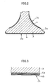
- Fig. 1 illustrates the first embodiment of a poppet valve used as an exhaust valve according to the present invention.
- the poppet valve 1 consists of a valve stem 2 and a valve head 3 made of austenite heat-resistant steel.
- the valve head 3 consists of a front face 3b opposite a cylinder (not shown) and a rear portion 3c in an exhaust port. The whole surface of the valve head 3 except a valve face 3a is covered with a film 4 made of heat-resistant heat-insulating material.
- the heat-insulating material includes ceramic oxides such as alumina, cordierite, zirconia, zircon and titanium oxide; ceramic carbides such as silicon carbide; ceramic nitrides such as silicon niride; aluminum silicate; chromium oxide; WC-Co alloy; WC-Ni-W-Cr 3 C 2 alloy and Cr 3 C 2 -Ni-Cr alloy.
- the film 4 may be made using gas flame or arc spraying, plasma spraying, explosion spraying, sputtering or ion plating.
- the film 4 may have thickness of 0.1 to 2.0 mm to insulate heat and decrease weight.
- the heat-insulating material as above may be sprayed after the surface on which the film is formed is made rough by using shot blasting or mechanical working.
- a film 4 that consists of multiple layers having different contents of heat-insulating material may be formed.
- the first layer 4a is a highly adhesive binding layer made from the same material as the valve. Heat-insulating materials are increased in conjunction with the increase in layers.
- An outermost layer 4b is made only of heat-insulating material. The surface of the film may be sprayed without making a rough surface. In the case of intake valves, the film 4 on the rear portion 3c may be omitted.
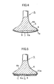
- Fig. 4 illustrates the second embodiment of the present invention, in which a thin convex heat-shielding plate 7 made of heat-insulating material, as described above, or heat-resistant material such as heat-resistant steel is mounted to a front face 6a of a valve head 6 of a martensite heat-resistant steel poppet valve 5 to form a heat-insulating space 8 between the plate 7 and the front face 6.
- a thin convex heat-shielding plate 7 made of heat-insulating material, as described above, or heat-resistant material such as heat-resistant steel is mounted to a front face 6a of a valve head 6 of a martensite heat-resistant steel poppet valve 5 to form a heat-insulating space 8 between the plate 7 and the front face 6.
- an L-sectioned mounting portion 7a is formed on the circumferential end, and is engaged in an annular groove 9 on the circumferential end of the front face 6a. Then, the circumferential end of the front face 6a is plastically reconfigured inwards.
- the circumferential end of the heat-shielding plate 7 may be welded to the front face 6a.
- the convex heat-shielding plate 7 provides sufficient bending strength against pressure and decreases concave deformation.
- Fig. 5 illustrates the third embodiment of a poppet valve according to the present invention in which a heat-shielding plate 10, made of the same material as the above, has multiple reinforcement ribs 11 on the upper surface.
- a mounting portion 10a formed in the upper circumferential end is fixed to the circumferential end of a front face by the above caulking method to form a heat-insulating space 8 against the front face 6a.
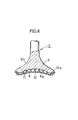
- Fig. 6 illustrates the fourth embodiment of a poppet valve according to the present invention in which a front face 6a of a poppet valve 5 is convex.
- a concave heat-shielding plate 12 having multiple reinforcement ribs 11 on the upper surface is fixed to the circumferential end of the front face 6a using an L-shaped mounting portion 12a on the circumferential end of the plate 12 by the above caulking method.
- the heat-insulating space 8 is formed between the front face 6a and the heat-shielding plate 12 while the upper ends of the reinforcement ribs 11 are engaged on the front face 6a.
- the reinforcement rib may be formed as grid, concentric circle, vortex, parallel plate, corrugated plate, incomplete circle, arc and protrusion.
- the reinforcement rib may be provided on the front face 6a.
- the reinforcement rib as described above, may be provided in the embodiment in Fig. 4.
- the film may be formed on the rear portion 6b similar to the first embodiment in case of exhaust valves.
- a light heat-insulating filler such as glass wool and rock wool or a heat-insulating gas such as Ar may be enclosed under ordinary or high pressure. Space 8 may be vacuous.
- the front face 3b and the rear portion 3c subjected to a high-temperature combustion or exhaust gas are covered with the film 4 made of heat-insulating material.
- the heat-shielding plates 7,10,12 are mounted to the front face 6a to form a heat-insulating space 8.
- Heat into the valve head 3,6 decreases, and generally dissipates through a valve seat or a valve guide thereby decreasing valve temperature during operation and improving durability. Heat into the valve head 3,6 decreases the heat loss rate and increases thermal efficiency thereby improving engine performance such as output and fuel efficiency.
- valve Furthermore, a decrease in thermal load enables the valve to be made of low-cost material such as carbon steel or mechanical structural steel.
- the present invention allows for poppet valves to be made of lightweight metals such as Al, Mg and Ti alloys which were heretofore difficult in use thereby reducing the inertia mass of a valve-operating mechanism to decrease mechanical loss such as friction so as to achieve double improvement in engine performance with decreased heat loss.
Landscapes
- Chemical & Material Sciences (AREA)
- Engineering & Computer Science (AREA)
- Mechanical Engineering (AREA)
- Organic Chemistry (AREA)
- Materials Engineering (AREA)
- Metallurgy (AREA)
- Chemical Kinetics & Catalysis (AREA)
- General Engineering & Computer Science (AREA)
- Physics & Mathematics (AREA)
- Plasma & Fusion (AREA)
- Inorganic Chemistry (AREA)
- Lift Valve (AREA)
- Cylinder Crankcases Of Internal Combustion Engines (AREA)
- Coating By Spraying Or Casting (AREA)
Abstract
Description
Claims (16)
- A poppet valve comprising:a valve stem; anda valve head at an end of the valve stem, a surface of the valve head being covered with a film made of heat-resistant heat-insulating material.
- A poppet valve as claimed in claim 1 wherein the surface of the valve head except a valve face is covered with the film.
- A poppet valve as claimed in claim 1 wherein the valve head comprises a front face opposite a cylinder and a rear portion, only the front face being covered with the film when the poppet valve is used as intake valve.
- A poppet valve as claimed in claim 1 wherein the heat insulating material is comprised of one of oxide, carbide and nitride ceramics.
- A poppet valve as claimed in claim 1 wherein the surface of the valve head to be covered with the film is rough.
- A poppet valve as claimed in claim 1 wherein the film comprises multiple layers with a first layer of the film being made from the same material as the valve itself and additional layers containing increased amounts of heat-insulating material with each successive layers; an outermost layer being only the heat-insulating material.
- A poppet valve comprising:a valve stem;a valve head at an end of the valve stem, anda heat-shielding plate fixed over a front face of the valve head opposite a cylinder to form heat-insulating space between the front face and the heat-shielding plate with said plate being made of heat-resistant heat-insulating material.
- A poppet valve as claimed in claim 7 wherein a circumferential end of the heat-shielding plate is fixed to a circumferential end of the front face of the valve head by caulking.
- A poppet valve as claimed in claim 7 wherein the heat-shielding plate is concave.
- A poppet valve as claimed in claim 7 wherein a rib is provided on the heat-shielding plate or the front face of the valve head to contact the other in the heat insulating space.
- A poppet valve as claimed in claim 10 wherein multiple ribs are provided in the heat-insulating space.
- A poppet valve as claimed in claim 7 wherein a heat-resistant heat-insulating filler is enclosed in the heat-insulating space.
- A poppet valve as claimed in claim 12 wherein the filler is glass or rock wool.
- A poppet valve as claimed in claim 7 wherein a heat insulating gas is enclosed in the heat-insulating space.
- A poppet valve as claimed in claim 14 wherein the heat-insulating gas is Ar.
- A poppet valve as claimed in claim 7 wherein the heat-insulating space is vacuous.
Applications Claiming Priority (2)
| Application Number | Priority Date | Filing Date | Title |
|---|---|---|---|
| JP2002109861A JP2003307105A (en) | 2002-04-12 | 2002-04-12 | Engine valve |
| JP2002109861 | 2002-04-12 |
Publications (2)
| Publication Number | Publication Date |
|---|---|
| EP1353045A2 true EP1353045A2 (en) | 2003-10-15 |
| EP1353045A3 EP1353045A3 (en) | 2004-03-10 |
Family
ID=28449972
Family Applications (1)
| Application Number | Title | Priority Date | Filing Date |
|---|---|---|---|
| EP03007678A Withdrawn EP1353045A3 (en) | 2002-04-12 | 2003-04-03 | Poppet valve |
Country Status (4)
| Country | Link |
|---|---|
| EP (1) | EP1353045A3 (en) |
| JP (1) | JP2003307105A (en) |
| KR (1) | KR20030081165A (en) |
| CN (1) | CN1451850A (en) |
Cited By (15)
| Publication number | Priority date | Publication date | Assignee | Title |
|---|---|---|---|---|
| WO2006097264A1 (en) * | 2005-03-18 | 2006-09-21 | Man B & W Diesel Aktiengesellschaft | Gas shuttle valve provided with an anti-corrosive layer |
| DE102006053550A1 (en) * | 2006-11-14 | 2008-05-15 | Man Diesel Se | Internal-combustion engine i.e. diesel internal-combustion engine, has valve cone of outlet and inlet valves coated areawise with thermal damping material and insulating material, where sections of cone are coated with damping material |
| DE102006061128A1 (en) * | 2006-12-22 | 2008-06-26 | Mahle International Gmbh | Cylinder valve, for an internal combustion motor, has a valve plate with a hollow zone and surface projections at the base with a hollow shaft for a coolant feed liquefying under heat |
| EP1746179A3 (en) * | 2005-06-22 | 2009-09-30 | Yamaha Hatsudoki Kabushiki Kaisha | Titanium part for internal combustion engine |
| US20100077983A1 (en) * | 2008-10-01 | 2010-04-01 | Aisan Kogyo Kabushiki Kaisha | Engine valves |
| EP2182183A1 (en) * | 2008-10-31 | 2010-05-05 | Mahle International GmbH | Mobile sealing body of a valve exposed to hot gasses |
| US8376721B2 (en) | 2006-11-01 | 2013-02-19 | Borgwarner Inc. | Turbine heat shield assembly |
| DE102013213268A1 (en) * | 2013-07-05 | 2015-01-08 | Mahle International Gmbh | Built hollow valve |
| WO2015182248A1 (en) * | 2014-05-30 | 2015-12-03 | Toyota Jidosha Kabushiki Kaisha | Supercharged internal combustion engine |
| DE102014219917A1 (en) * | 2014-10-01 | 2016-04-07 | Mahle International Gmbh | Eddy current valve |
| EP3106634A4 (en) * | 2014-02-12 | 2017-11-29 | Nittan Valve Co., Ltd. | Poppet valve |
| WO2019086244A1 (en) * | 2017-10-30 | 2019-05-09 | Eaton Intelligent Power Limited | Poppet valve |
| DE102018118791A1 (en) * | 2018-08-02 | 2020-02-06 | Federal-Mogul Valvetrain Gmbh | Poppet valve with a high temperature coating |
| US10731538B2 (en) | 2017-12-19 | 2020-08-04 | Toyota Jidosha Kabushiki Kaisha | Internal combustion engine |
| US11767774B2 (en) | 2017-10-30 | 2023-09-26 | Eaton Intelligent Power Limited | Poppet valve |
Families Citing this family (14)
| Publication number | Priority date | Publication date | Assignee | Title |
|---|---|---|---|---|
| JP2013170555A (en) * | 2012-02-23 | 2013-09-02 | Mazda Motor Corp | Heat insulation structure and method of manufacturing the same |
| KR101563533B1 (en) | 2012-10-31 | 2015-10-27 | 후쿠다 킨조쿠 하쿠훈 코교 가부시키가이샤 | Ni-Cr-Co-BASED ALLOY HAVING HIGH-TEMPERATURE CORROSION RESISTANCE PROPERTIES, AND POPPET VALVE HAVING SURFACE MODIFIED WITH SAME |
| WO2014125843A1 (en) * | 2013-02-15 | 2014-08-21 | トヨタ自動車 株式会社 | Poppet valve |
| JP6109945B2 (en) * | 2013-09-11 | 2017-04-05 | 日鍛バルブ株式会社 | Engine valve and method for manufacturing engine valve |
| RU2641870C1 (en) | 2014-02-10 | 2018-01-22 | Ниттан Вэлв Ко., Лтд. | Hollow poppet valve |
| KR101566743B1 (en) | 2014-04-18 | 2015-11-06 | 현대자동차 주식회사 | Exhaust valve for engine |
| KR101575328B1 (en) | 2014-04-29 | 2015-12-07 | 현대자동차 주식회사 | Intake valve for engine |
| JP6609124B2 (en) * | 2015-06-23 | 2019-11-20 | イビデン株式会社 | Engine valve and manufacturing method thereof |
| JP6832204B2 (en) * | 2017-03-27 | 2021-02-24 | 三菱重工業株式会社 | Valve gear, turbine housing, exhaust turbine turbocharger and engine |
| KR102285017B1 (en) | 2018-03-20 | 2021-08-04 | 니탄 밸브 가부시키가이샤 | Hollow Poppet Valve for Exhaust |
| EP3882438A4 (en) | 2018-11-12 | 2021-11-24 | Nittan Valve Co., Ltd. | METHOD OF MANUFACTURING AN ENGINE MUSHROOM VALVE |
| JP7329201B2 (en) | 2020-03-30 | 2023-08-18 | 株式会社Nittan | Manufacturing method of engine poppet valve |
| JP7687561B2 (en) * | 2021-01-25 | 2025-06-03 | フジオーゼックス株式会社 | Hollow Engine Valve |
| CA3226191A1 (en) * | 2021-08-04 | 2023-02-09 | Wolfgang Fimml | Cylinder liner for an internal combustion engine and a method of producing the same |
Family Cites Families (5)
| Publication number | Priority date | Publication date | Assignee | Title |
|---|---|---|---|---|
| GB618607A (en) * | 1946-06-04 | 1949-02-24 | William Thomas Davies | Improvements in or relating to the production of corrosion resistant coatings on poppet valves for internal-combustion engines |
| US4530322A (en) * | 1980-10-31 | 1985-07-23 | Nippon Kokan Kabushiki Kaisha | Exhaust valve for diesel engine and production thereof |
| DE3150708A1 (en) * | 1981-12-22 | 1983-07-07 | Gesenkschmiede Schneider Gmbh, 7080 Aalen | Disc valve as an exhaust valve for engines with a high load capacity |
| NO831216L (en) * | 1982-04-07 | 1983-10-31 | Castolin S.A, | VALVE FOR DIESEL ENGINES |
| US5543029A (en) * | 1994-04-29 | 1996-08-06 | Fuji Oozx Inc. | Properties of the surface of a titanium alloy engine valve |
-
2002
- 2002-04-12 JP JP2002109861A patent/JP2003307105A/en active Pending
-
2003
- 2003-04-03 EP EP03007678A patent/EP1353045A3/en not_active Withdrawn
- 2003-04-09 CN CN03109541A patent/CN1451850A/en active Pending
- 2003-04-11 KR KR10-2003-0022948A patent/KR20030081165A/en not_active Withdrawn
Cited By (22)
| Publication number | Priority date | Publication date | Assignee | Title |
|---|---|---|---|---|
| WO2006097264A1 (en) * | 2005-03-18 | 2006-09-21 | Man B & W Diesel Aktiengesellschaft | Gas shuttle valve provided with an anti-corrosive layer |
| EP1746179A3 (en) * | 2005-06-22 | 2009-09-30 | Yamaha Hatsudoki Kabushiki Kaisha | Titanium part for internal combustion engine |
| US7794846B2 (en) | 2005-06-22 | 2010-09-14 | Yamaha Hatsudoki Kabushiki Kaisha | Titanium part for internal combustion engine |
| US8376721B2 (en) | 2006-11-01 | 2013-02-19 | Borgwarner Inc. | Turbine heat shield assembly |
| DE102006053550A1 (en) * | 2006-11-14 | 2008-05-15 | Man Diesel Se | Internal-combustion engine i.e. diesel internal-combustion engine, has valve cone of outlet and inlet valves coated areawise with thermal damping material and insulating material, where sections of cone are coated with damping material |
| DE102006061128A1 (en) * | 2006-12-22 | 2008-06-26 | Mahle International Gmbh | Cylinder valve, for an internal combustion motor, has a valve plate with a hollow zone and surface projections at the base with a hollow shaft for a coolant feed liquefying under heat |
| DE102006061128B4 (en) * | 2006-12-22 | 2015-06-11 | Mahle International Gmbh | Gas exchange valve of an internal combustion engine |
| US20100077983A1 (en) * | 2008-10-01 | 2010-04-01 | Aisan Kogyo Kabushiki Kaisha | Engine valves |
| DE102009042545B4 (en) * | 2008-10-01 | 2013-01-17 | Aisan Kogyo K.K. | engine valves |
| US8726873B2 (en) | 2008-10-31 | 2014-05-20 | Mahle International Gmbh | Moveable valve sealing body exposed to hot gases |
| DE102008054266A1 (en) * | 2008-10-31 | 2010-05-06 | Mahle International Gmbh | Movable, hot gases exposed closure body of a valve |
| EP2182183A1 (en) * | 2008-10-31 | 2010-05-05 | Mahle International GmbH | Mobile sealing body of a valve exposed to hot gasses |
| DE102013213268A1 (en) * | 2013-07-05 | 2015-01-08 | Mahle International Gmbh | Built hollow valve |
| EP3106634A4 (en) * | 2014-02-12 | 2017-11-29 | Nittan Valve Co., Ltd. | Poppet valve |
| WO2015182248A1 (en) * | 2014-05-30 | 2015-12-03 | Toyota Jidosha Kabushiki Kaisha | Supercharged internal combustion engine |
| CN106414984A (en) * | 2014-05-30 | 2017-02-15 | 丰田自动车株式会社 | Supercharged internal combustion engine |
| CN106414984B (en) * | 2014-05-30 | 2018-09-28 | 丰田自动车株式会社 | Booster-type internal combustion engine |
| DE102014219917A1 (en) * | 2014-10-01 | 2016-04-07 | Mahle International Gmbh | Eddy current valve |
| WO2019086244A1 (en) * | 2017-10-30 | 2019-05-09 | Eaton Intelligent Power Limited | Poppet valve |
| US11767774B2 (en) | 2017-10-30 | 2023-09-26 | Eaton Intelligent Power Limited | Poppet valve |
| US10731538B2 (en) | 2017-12-19 | 2020-08-04 | Toyota Jidosha Kabushiki Kaisha | Internal combustion engine |
| DE102018118791A1 (en) * | 2018-08-02 | 2020-02-06 | Federal-Mogul Valvetrain Gmbh | Poppet valve with a high temperature coating |
Also Published As
| Publication number | Publication date |
|---|---|
| KR20030081165A (en) | 2003-10-17 |
| EP1353045A3 (en) | 2004-03-10 |
| JP2003307105A (en) | 2003-10-31 |
| CN1451850A (en) | 2003-10-29 |
Similar Documents
| Publication | Publication Date | Title |
|---|---|---|
| EP1353045A2 (en) | Poppet valve | |
| US5320909A (en) | Ceramic thermal barrier coating for rapid thermal cycling applications | |
| US7665307B2 (en) | Dual wall combustor liner | |
| US6887587B2 (en) | Reflective coatings to reduce radiation heat transfer | |
| CN1890456B (en) | Components with thermal insulation and erosion protection | |
| US8722202B2 (en) | Method and system for enhancing heat transfer of turbine engine components | |
| JPH0233454A (en) | Structure for adiabatic engine | |
| JP2010084693A (en) | Engine valve | |
| EP0321159B1 (en) | Heat insulating engine | |
| US7445851B2 (en) | Heat-insulating layer system | |
| CN106715880B (en) | Piston, piston machine with piston and automobile with piston machine | |
| JPH0131024B2 (en) | ||
| US4600038A (en) | Engine part | |
| JP4294736B2 (en) | Gas turbine equipment with combustion chamber lined with ceramic blocks | |
| WO2005108747A1 (en) | Turbocharger with reduced thermal inertia and method of producing the same | |
| JPH0223767Y2 (en) | ||
| JPH04147957A (en) | Heat insulating aluminum-based member | |
| JPH08226304A (en) | Ceramic stator blade | |
| CA3001802A1 (en) | Thermal coating system with aluminide | |
| JP2870069B2 (en) | Insulated engine structure | |
| US11933204B2 (en) | Systems and methods for thermal barrier coatings to modify engine component thermal characteristics | |
| JP4129518B2 (en) | Gas turbine combustor wall structure | |
| CN114215623A (en) | Coated valve for internal combustion engine and method for manufacturing same | |
| CN108700296A (en) | Flow elements and methods for coating flow elements | |
| JPH07310991A (en) | Rotary type heat exchange equipment |
Legal Events
| Date | Code | Title | Description |
|---|---|---|---|
| PUAI | Public reference made under article 153(3) epc to a published international application that has entered the european phase |
Free format text: ORIGINAL CODE: 0009012 |
|
| AK | Designated contracting states |
Kind code of ref document: A2 Designated state(s): AT BE BG CH CY CZ DE DK EE ES FI FR GB GR HU IE IT LI LU MC NL PT RO SE SI SK TR |
|
| AX | Request for extension of the european patent |
Extension state: AL LT LV MK |
|
| PUAL | Search report despatched |
Free format text: ORIGINAL CODE: 0009013 |
|
| AK | Designated contracting states |
Kind code of ref document: A3 Designated state(s): AT BE BG CH CY CZ DE DK EE ES FI FR GB GR HU IE IT LI LU MC NL PT RO SE SI SK TR |
|
| AX | Request for extension of the european patent |
Extension state: AL LT LV MK |
|
| AKX | Designation fees paid | ||
| REG | Reference to a national code |
Ref country code: DE Ref legal event code: 8566 |
|
| STAA | Information on the status of an ep patent application or granted ep patent |
Free format text: STATUS: THE APPLICATION IS DEEMED TO BE WITHDRAWN |
|
| 18D | Application deemed to be withdrawn |
Effective date: 20040311 |