EP1353063A2 - Système d'injection de carburant pour un moteur à piston - Google Patents
Système d'injection de carburant pour un moteur à piston Download PDFInfo
- Publication number
- EP1353063A2 EP1353063A2 EP03252114A EP03252114A EP1353063A2 EP 1353063 A2 EP1353063 A2 EP 1353063A2 EP 03252114 A EP03252114 A EP 03252114A EP 03252114 A EP03252114 A EP 03252114A EP 1353063 A2 EP1353063 A2 EP 1353063A2
- Authority
- EP
- European Patent Office
- Prior art keywords
- fuel
- pressure accumulator
- injection system
- fuel injection
- body part
- Prior art date
- Legal status (The legal status is an assumption and is not a legal conclusion. Google has not performed a legal analysis and makes no representation as to the accuracy of the status listed.)
- Granted
Links
Images


Classifications
-
- F—MECHANICAL ENGINEERING; LIGHTING; HEATING; WEAPONS; BLASTING
- F02—COMBUSTION ENGINES; HOT-GAS OR COMBUSTION-PRODUCT ENGINE PLANTS
- F02M—SUPPLYING COMBUSTION ENGINES IN GENERAL WITH COMBUSTIBLE MIXTURES OR CONSTITUENTS THEREOF
- F02M63/00—Other fuel-injection apparatus having pertinent characteristics not provided for in groups F02M39/00 - F02M57/00 or F02M67/00; Details, component parts, or accessories of fuel-injection apparatus, not provided for in, or of interest apart from, the apparatus of groups F02M39/00 - F02M61/00 or F02M67/00; Combination of fuel pump with other devices, e.g. lubricating oil pump
- F02M63/02—Fuel-injection apparatus having several injectors fed by a common pumping element, or having several pumping elements feeding a common injector; Fuel-injection apparatus having provisions for cutting-out pumps, pumping elements, or injectors; Fuel-injection apparatus having provisions for variably interconnecting pumping elements and injectors alternatively
- F02M63/0225—Fuel-injection apparatus having a common rail feeding several injectors ; Means for varying pressure in common rails; Pumps feeding common rails
-
- F—MECHANICAL ENGINEERING; LIGHTING; HEATING; WEAPONS; BLASTING
- F02—COMBUSTION ENGINES; HOT-GAS OR COMBUSTION-PRODUCT ENGINE PLANTS
- F02M—SUPPLYING COMBUSTION ENGINES IN GENERAL WITH COMBUSTIBLE MIXTURES OR CONSTITUENTS THEREOF
- F02M55/00—Fuel-injection apparatus characterised by their fuel conduits or their venting means; Arrangements of conduits between fuel tank and pump F02M37/00
- F02M55/02—Conduits between injection pumps and injectors, e.g. conduits between pump and common-rail or conduits between common-rail and injectors
- F02M55/025—Common rails
-
- F—MECHANICAL ENGINEERING; LIGHTING; HEATING; WEAPONS; BLASTING
- F02—COMBUSTION ENGINES; HOT-GAS OR COMBUSTION-PRODUCT ENGINE PLANTS
- F02M—SUPPLYING COMBUSTION ENGINES IN GENERAL WITH COMBUSTIBLE MIXTURES OR CONSTITUENTS THEREOF
- F02M2200/00—Details of fuel-injection apparatus, not otherwise provided for
- F02M2200/40—Fuel-injection apparatus with fuel accumulators, e.g. a fuel injector having an integrated fuel accumulator
Definitions
- This invention relates to a fuel injection system for a piston engine as set forth in the preamble of claim 1.
- the common pressure accumulator must be designed to be very strong to withstand high pressures, typically of the order of > 100 MPa.
- pressure accumulators are typically cylindrical in design. This kind of design leads to a large wall thickness and thereby also, for example, the space requirement is large compared to the volume of the pressure accumulator.
- the present invention provides a fuel injection system for a piston engine as set out in the appended claim 1.
- Preferred or optional features of the invention are defined in the other claims.
- a fuel injection system for a piston engine comprising a block of the engine with cylinders arranged therein and at least one fuel injector nozzle arranged for each cylinder in connection with the fuel injection system, comprises a dedicated fuel pressure accumulator for each cylinder.
- the fuel pressure accumulator for each cylinder is arranged at least partially within the cylinder head of the engine.
- the cylinder head construction enveloping the accumulator may serve e.g. as a supporting casing for the accumulator.
- the pressure accumulators are preferably in fluid connection with each other.
- the connection may be realized by means of a tube system external to the cylinder head.
- the total volume of the pressure accumulator is preferably at least 30 times greater than the volume of fuel injected by one injector nozzle during one combustion stroke of the engine. In this way, a proper pressure level may be maintained in the system also during injections.
- each cylinder comprises a separate cylinder head, into which the pressure accumulator is arranged to extend from outside the cylinder head to the injector nozzle.
- the accumulator is substantially enveloped by the cylinder head.
- the pressure accumulator consists of at least two separate chambers, in fluid connection with each other, and bounded by an at least partially common intermediate wall.
- control of the stresses in the pressure accumulator can be improved and the space requirements are reduced by the smaller wall thicknesses necessary.
- the pressure accumulator comprises a main chamber and at least one auxiliary chamber in fluid connection with each other by at least two different routes.
- the main chamber of the pressure accumulator may be connected to the fuel injector nozzle and the said at least one auxiliary chamber may be connected to a fuel channel feeding fuel to the pressure accumulator.
- the pressure accumulator preferably comprises a longitudinally elongated body part, a first end part of the body part and a second end part of the body part, in which the chambers of the pressure accumulator comprise spaces arranged in the body part, extending from one end thereof to the other end, with both of the end parts comprising at least one flow channel in connection with at least one of said spaces.
- the body part of the pressure accumulator may be essentially round in cross-section and the spaces may consist of essentially round spaces, such as bores, parallel with the longitudinal axis of the body part.
- the spaces are arranged essentially symmetrically with the centre axis of the body part in the cross section thereof.
- FIG. 1 schematically shows a part of a piston engine 2 with a fuel injection system 1 connected thereto.
- the basic design of the piston engine is known as such, as is the fuel injection system.
- the piston engine comprises a number of cylinders 4 arranged in the block 3 thereof, each of the cylinders having a separate cylinder head 7.
- Each cylinder is provided with at least one fuel injector nozzle 5.
- the fuel injection system is a so-called common rail system, so that it comprises at least one fuel pressure accumulator 6.
- each cylinder 4 is provided with an individual, separate i.e. dedicated fuel pressure accumulator 6.
- the system is very compact and advantageous, as the fuel pressure accumulator of each cylinder 4 is arranged to be at least partially enveloped by the engine cylinder head 7.
- the fuel pressure accumulators 6 take up less space and, on the other hand, the construction of the cylinder head can be used as a cover for the pressure accumulator.
- a fuel leak for example, can in its first phase be limited to within the space of the pressure accumulator in the cylinder head 7, whereby it can also be noticed faster.
- heat is convected from the cylinder head to the pressure accumulator, heating the fuel.
- This solution also brings the pressure accumulator closer to the fuel injector nozzle 5, whereby flow pressure losses between the pressure accumulator 6 and the injector nozzle 5 are reduced.
- the pressure accumulator 6 is almost totally enclosed within the cylinder head and only the parts necessary for connecting the fuel channel are left outside the cylinder head.
- the pressure accumulators 6 are in fluid connection with each other as well as with the rest of the fuel injection system 1 mainly by means of a tube system 8 external to the cylinder head.
- the tube system 8 is connected with the pressure accumulator 6 by means of a flow channel 10.1 of a first end part 10.
- the tube system 8 is in connection with a high-pressure fuel pump 8.1.
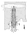
- Figure 2 shows an advantageous embodiment of pressure accumulator 6 arranged in the cylinder head 7, in connection with the fuel injector nozzle 5.
- the fuel pressure accumulator 6 and the injector nozzle are arranged to be substantially in direct connection with each other, via only a second end part 11 of the pressure accumulator 6.
- the second end part 11 comprises a tubular extension 11.2 provided with a flow channel 11.1, arranged to extend to the fuel injector nozzle 5 so that together they form a closed fluid connection for the fuel.
- the pressure accumulator 6 is arranged to comprise at least two separate chambers 6.1, 6.2. In this embodiment there are five of them, one 6.1 of which is on the centre axis of the pressure accumulator and others arranged symmetrically in relation to the centre axis, as can be seen in figure 3.
- This kind of solution enables the outer wall to be made with a thinner wall thickness, as part of the stresses caused by the pressure can be self-compensated by means of the pressure chamber divided into parts so that the total pressure exerted on the outer surface is reduced.
- the main point is to produce a number of partial volumes, which are then suitably connected to each other in the pressure accumulator 6. According to the invention the total volume formed by the partial volumes is thus at least 30 times greater than the volume of fuel injected by one injector nozzle 5 during one combustion stroke of the engine.
- the pressure accumulator can thus be realised as shown in figure 2, wherein it is formed by a so-called main chamber 6.1, connected via the end part 11 to the fuel injector nozzle 5, and by a plurality of auxiliary chambers 6.2.
- the fuel channels 8 are primarily connected to auxiliary chambers 6.2. All auxiliary chambers are, however in fluid connection with each other as well as with the main chamber. Channels 6.4, 6.5 have been arranged for providing this connection to the pressure accumulator.
- the chambers 6.1, 6.2 are connected via both their ends. Grooves or the like 6.4 have been arranged in the first end by means of which the chambers 6.1, 6.2 are in connection with each other. The other end is provided with bores or the like 6.5.
- a corresponding functionality can also be provided by means of a solution wherein the body part only comprises the longitudinal bores for spaces 6.1, 6.2 and the channels made for connecting them are arranged in the end parts 10, 11 by means of grooves, bores or the like.
- the pressure accumulator 6 comprises a longitudinally elongated body part 9, preferably of cylindrical form, a first end part 10 and a second end part 11.
- the chambers 6.1, 6.2 comprise spaces arranged inside the body part extending from one end thereof towards the other end, of which chambers only chamber 6.1 extends through the body part and the other chambers 6.2 are connected to the chamber 6.1 via bores 6.5 or the like. Fuel is fed to the pressure accumulator 6 via the end parts and further fed to the fuel injector nozzles 5.
- Figure 3 shows in greater detail a method of arranging the chambers in the cross-section of the pressure accumulator 6.
- the chambers 6.1, 6.2 are preferably arranged so that they are essentially symmetrically located in relation to the centre axis of the body part 9.
- one of the chambers 6.1, which in this embodiment extends through the body part 9, is on its centre axis and the other chambers 6.2 are arranged symmetrically in its cross-section.
- Two adjacent chambers are always determined by a common intermediate wall 6.3 and as the two adjacent chambers have an essentially similar pressure, the stresses compensate each other to a considerable degree.
Landscapes
- Engineering & Computer Science (AREA)
- Chemical & Material Sciences (AREA)
- Combustion & Propulsion (AREA)
- Mechanical Engineering (AREA)
- General Engineering & Computer Science (AREA)
- Fuel-Injection Apparatus (AREA)
Applications Claiming Priority (2)
| Application Number | Priority Date | Filing Date | Title |
|---|---|---|---|
| FI20020667 | 2002-04-08 | ||
| FI20020667A FI116158B (fi) | 2002-04-08 | 2002-04-08 | Mäntämoottorin polttoaineen syöttöjärjestelmä |
Publications (3)
| Publication Number | Publication Date |
|---|---|
| EP1353063A2 true EP1353063A2 (fr) | 2003-10-15 |
| EP1353063A3 EP1353063A3 (fr) | 2004-10-06 |
| EP1353063B1 EP1353063B1 (fr) | 2007-06-13 |
Family
ID=8563717
Family Applications (1)
| Application Number | Title | Priority Date | Filing Date |
|---|---|---|---|
| EP03252114A Expired - Lifetime EP1353063B1 (fr) | 2002-04-08 | 2003-04-03 | Système d'injection de carburant pour un moteur à piston |
Country Status (7)
| Country | Link |
|---|---|
| US (1) | US6851412B2 (fr) |
| EP (1) | EP1353063B1 (fr) |
| JP (1) | JP4237526B2 (fr) |
| AT (1) | ATE364786T1 (fr) |
| DE (1) | DE60314321T2 (fr) |
| DK (1) | DK1353063T3 (fr) |
| FI (1) | FI116158B (fr) |
Cited By (2)
| Publication number | Priority date | Publication date | Assignee | Title |
|---|---|---|---|---|
| WO2009033304A1 (fr) | 2007-09-13 | 2009-03-19 | Ganser-Hydromag Ag | Dispositif d'injection de carburant |
| US20210231087A1 (en) * | 2018-07-26 | 2021-07-29 | Liebherr-Components Deggendorf Gmbh | Connecting piece for a fuel injector of an internal combustion engine |
Families Citing this family (5)
| Publication number | Priority date | Publication date | Assignee | Title |
|---|---|---|---|---|
| DE102005012928A1 (de) * | 2005-03-21 | 2006-09-28 | Robert Bosch Gmbh | Kraftstoffeinspritzeinrichtung für eine mehrzylindrige Brennkraftmaschine |
| DE102005026600B4 (de) * | 2005-06-09 | 2013-08-22 | Man Diesel & Turbo Se | Brennkraftmaschine |
| US8205598B2 (en) * | 2010-02-08 | 2012-06-26 | International Engine Intellectual Property Company, Llc | Fuel injector nozzle |
| US8622046B2 (en) | 2010-06-25 | 2014-01-07 | Caterpillar Inc. | Fuel system having accumulators and flow limiters |
| DE102021200154A1 (de) * | 2021-01-11 | 2022-07-14 | Robert Bosch Gesellschaft mit beschränkter Haftung | Kraftstoffeinspritzvorrichtung |
Family Cites Families (12)
| Publication number | Priority date | Publication date | Assignee | Title |
|---|---|---|---|---|
| US5035221A (en) | 1989-01-11 | 1991-07-30 | Martin Tiby M | High pressure electronic common-rail fuel injection system for diesel engines |
| DE4344190A1 (de) * | 1993-12-23 | 1995-06-29 | Orange Gmbh | Kraftstoffeinspritzvorrichtung mit Hochdruck-Kraftstoffspeicher |
| JP3521555B2 (ja) * | 1995-06-30 | 2004-04-19 | 日産自動車株式会社 | 直接噴射型火花点火機関の燃料供給装置 |
| FR2748783B1 (fr) * | 1996-05-17 | 1998-08-14 | Melchior Jean F | Dispositif d'injection de combustible liquide pour moteur a combustion interne |
| DE19712135C1 (de) * | 1997-03-22 | 1998-08-13 | Mtu Friedrichshafen Gmbh | Kraftstoffeinspritzsystem für eine Brennkraftmaschine |
| DE19842067A1 (de) * | 1998-09-15 | 2000-03-16 | Daimler Chrysler Ag | Kraftstoffeinspritzanlage für eine Dieselbrennkraftmaschine |
| JP2000205081A (ja) * | 1999-01-06 | 2000-07-25 | Usui Internatl Ind Co Ltd | ディ―ゼル内燃機関の蓄圧式燃料噴射システム |
| DE19936685A1 (de) | 1999-08-04 | 2001-02-22 | Bosch Gmbh Robert | Kraftstoffhochdruckspeicher |
| DE19948339C1 (de) | 1999-10-07 | 2000-12-14 | Bosch Gmbh Robert | Kraftstoffhochdruckspeicher |
| DE10114252C2 (de) * | 2001-03-22 | 2003-01-30 | Mtu Friedrichshafen Gmbh | Verfahren zum Einspritzen von Kraftstoff in die Brennräume einer Brennkraftmaschine, sowie Kraftstoffeinspritzsystem für eine solche |
| DE10210282A1 (de) * | 2002-03-08 | 2003-09-25 | Bosch Gmbh Robert | Vorrichtung zum Einspritzen von Kraftstoff an stationären Verbrennungskraftmaschinen |
| DE10217383A1 (de) * | 2002-04-18 | 2003-11-13 | Siemens Ag | Zylinderkopf-integriertes Dieseleinspritzsytem mit Ölsensor |
-
2002
- 2002-04-08 FI FI20020667A patent/FI116158B/fi not_active IP Right Cessation
-
2003
- 2003-04-03 EP EP03252114A patent/EP1353063B1/fr not_active Expired - Lifetime
- 2003-04-03 AT AT03252114T patent/ATE364786T1/de active
- 2003-04-03 DK DK03252114T patent/DK1353063T3/da active
- 2003-04-03 DE DE60314321T patent/DE60314321T2/de not_active Expired - Lifetime
- 2003-04-07 US US10/411,597 patent/US6851412B2/en not_active Expired - Lifetime
- 2003-04-07 JP JP2003102430A patent/JP4237526B2/ja not_active Expired - Fee Related
Cited By (4)
| Publication number | Priority date | Publication date | Assignee | Title |
|---|---|---|---|---|
| WO2009033304A1 (fr) | 2007-09-13 | 2009-03-19 | Ganser-Hydromag Ag | Dispositif d'injection de carburant |
| US8336524B2 (en) | 2007-09-13 | 2012-12-25 | Ganser-Hydromag Ag | Fuel injection device |
| US20210231087A1 (en) * | 2018-07-26 | 2021-07-29 | Liebherr-Components Deggendorf Gmbh | Connecting piece for a fuel injector of an internal combustion engine |
| US11542902B2 (en) * | 2018-07-26 | 2023-01-03 | Liebherr-Components Deggendorf Gmbh | Connecting piece for a fuel injector of an internal combustion engine |
Also Published As
| Publication number | Publication date |
|---|---|
| DE60314321D1 (de) | 2007-07-26 |
| JP4237526B2 (ja) | 2009-03-11 |
| US6851412B2 (en) | 2005-02-08 |
| FI20020667A7 (fi) | 2003-10-09 |
| US20030230284A1 (en) | 2003-12-18 |
| FI20020667A0 (fi) | 2002-04-08 |
| EP1353063A3 (fr) | 2004-10-06 |
| JP2003293894A (ja) | 2003-10-15 |
| ATE364786T1 (de) | 2007-07-15 |
| FI116158B (fi) | 2005-09-30 |
| DE60314321T2 (de) | 2008-02-14 |
| EP1353063B1 (fr) | 2007-06-13 |
| DK1353063T3 (da) | 2007-10-08 |
Similar Documents
| Publication | Publication Date | Title |
|---|---|---|
| US6776140B2 (en) | Fuel supply installation in the form of a common-rail system of an internal combustion engine having a plurality of cylinders | |
| CN101382108B (zh) | 低回流脉动燃料喷射泵 | |
| JP4547052B2 (ja) | 燃料供給システム | |
| US6405711B1 (en) | Fuel delivery module for fuel injected internal combustion engines | |
| US6786205B2 (en) | Hydraulically intensified high pressure fuel system for common rail application | |
| US6776138B2 (en) | Fuel injection device | |
| JPH1193798A (ja) | ユニット燃料インジェクタ | |
| EP1353063B1 (fr) | Système d'injection de carburant pour un moteur à piston | |
| EP0892170B1 (fr) | Dispositif a injection pour moteurs diesel | |
| US4398519A (en) | Fuel injection apparatus for internal combustion engines, in particular for diesel engines | |
| US20100147268A1 (en) | Fuel injection system for an internal combustion engine | |
| US11199168B2 (en) | Distributor apparatus of a common-rail system | |
| US7270114B2 (en) | Fuel injection system for internal combustion engines | |
| US20080041341A1 (en) | Fuel Supply Device | |
| US4640255A (en) | Fuel injection pump for internal combustion engines | |
| US6427665B1 (en) | High pressure fuel reservoir | |
| US6805102B2 (en) | Method of injecting fuel into the combustion chambers of an internal combustion engine, and fuel injection system for said engine | |
| KR101986067B1 (ko) | 고압 유체 레일 | |
| KR101440658B1 (ko) | 연료공급 시스템내의 연료저장부 | |
| US6923160B2 (en) | High-pressure fuel reservoir for a reservoir injection system | |
| EP0999362A2 (fr) | Système de carburant | |
| FI117984B (fi) | Polttomoottorin polttoaineen syöttöjärjestelmän painevarastojärjestely | |
| US8281767B2 (en) | Pressure booster with integrated pressure reservoir | |
| JP2007170209A (ja) | 内燃機関の燃料噴射装置 | |
| KR20210044297A (ko) | 주수 펌프 |
Legal Events
| Date | Code | Title | Description |
|---|---|---|---|
| PUAI | Public reference made under article 153(3) epc to a published international application that has entered the european phase |
Free format text: ORIGINAL CODE: 0009012 |
|
| AK | Designated contracting states |
Kind code of ref document: A2 Designated state(s): AT BE BG CH CY CZ DE DK EE ES FI FR GB GR HU IE IT LI LU MC NL PT RO SE SI SK TR |
|
| AX | Request for extension of the european patent |
Extension state: AL LT LV MK |
|
| PUAL | Search report despatched |
Free format text: ORIGINAL CODE: 0009013 |
|
| AK | Designated contracting states |
Kind code of ref document: A3 Designated state(s): AT BE BG CH CY CZ DE DK EE ES FI FR GB GR HU IE IT LI LU MC NL PT RO SE SI SK TR |
|
| AX | Request for extension of the european patent |
Extension state: AL LT LV MK |
|
| 17P | Request for examination filed |
Effective date: 20050314 |
|
| AKX | Designation fees paid |
Designated state(s): AT BE BG CH CY CZ DE DK EE ES FI FR GB GR HU IE IT LI LU MC NL PT RO SE SI SK TR |
|
| GRAP | Despatch of communication of intention to grant a patent |
Free format text: ORIGINAL CODE: EPIDOSNIGR1 |
|
| GRAS | Grant fee paid |
Free format text: ORIGINAL CODE: EPIDOSNIGR3 |
|
| 17Q | First examination report despatched |
Effective date: 20050809 |
|
| GRAA | (expected) grant |
Free format text: ORIGINAL CODE: 0009210 |
|
| AK | Designated contracting states |
Kind code of ref document: B1 Designated state(s): AT BE BG CH CY CZ DE DK EE ES FI FR GB GR HU IE IT LI LU MC NL PT RO SE SI SK TR |
|
| PG25 | Lapsed in a contracting state [announced via postgrant information from national office to epo] |
Ref country code: CH Free format text: LAPSE BECAUSE OF FAILURE TO SUBMIT A TRANSLATION OF THE DESCRIPTION OR TO PAY THE FEE WITHIN THE PRESCRIBED TIME-LIMIT Effective date: 20070613 Ref country code: LI Free format text: LAPSE BECAUSE OF FAILURE TO SUBMIT A TRANSLATION OF THE DESCRIPTION OR TO PAY THE FEE WITHIN THE PRESCRIBED TIME-LIMIT Effective date: 20070613 |
|
| REG | Reference to a national code |
Ref country code: GB Ref legal event code: FG4D |
|
| REG | Reference to a national code |
Ref country code: CH Ref legal event code: EP |
|
| REG | Reference to a national code |
Ref country code: IE Ref legal event code: FG4D |
|
| REF | Corresponds to: |
Ref document number: 60314321 Country of ref document: DE Date of ref document: 20070726 Kind code of ref document: P |
|
| PG25 | Lapsed in a contracting state [announced via postgrant information from national office to epo] |
Ref country code: SE Free format text: LAPSE BECAUSE OF FAILURE TO SUBMIT A TRANSLATION OF THE DESCRIPTION OR TO PAY THE FEE WITHIN THE PRESCRIBED TIME-LIMIT Effective date: 20070913 |
|
| REG | Reference to a national code |
Ref country code: DK Ref legal event code: T3 |
|
| NLV1 | Nl: lapsed or annulled due to failure to fulfill the requirements of art. 29p and 29m of the patents act | ||
| REG | Reference to a national code |
Ref country code: CH Ref legal event code: PL |
|
| PG25 | Lapsed in a contracting state [announced via postgrant information from national office to epo] |
Ref country code: BE Free format text: LAPSE BECAUSE OF FAILURE TO SUBMIT A TRANSLATION OF THE DESCRIPTION OR TO PAY THE FEE WITHIN THE PRESCRIBED TIME-LIMIT Effective date: 20070613 |
|
| PG25 | Lapsed in a contracting state [announced via postgrant information from national office to epo] |
Ref country code: SI Free format text: LAPSE BECAUSE OF FAILURE TO SUBMIT A TRANSLATION OF THE DESCRIPTION OR TO PAY THE FEE WITHIN THE PRESCRIBED TIME-LIMIT Effective date: 20070613 Ref country code: ES Free format text: LAPSE BECAUSE OF FAILURE TO SUBMIT A TRANSLATION OF THE DESCRIPTION OR TO PAY THE FEE WITHIN THE PRESCRIBED TIME-LIMIT Effective date: 20070924 Ref country code: CZ Free format text: LAPSE BECAUSE OF FAILURE TO SUBMIT A TRANSLATION OF THE DESCRIPTION OR TO PAY THE FEE WITHIN THE PRESCRIBED TIME-LIMIT Effective date: 20070613 Ref country code: BG Free format text: LAPSE BECAUSE OF FAILURE TO SUBMIT A TRANSLATION OF THE DESCRIPTION OR TO PAY THE FEE WITHIN THE PRESCRIBED TIME-LIMIT Effective date: 20070913 Ref country code: NL Free format text: LAPSE BECAUSE OF FAILURE TO SUBMIT A TRANSLATION OF THE DESCRIPTION OR TO PAY THE FEE WITHIN THE PRESCRIBED TIME-LIMIT Effective date: 20070613 Ref country code: PT Free format text: LAPSE BECAUSE OF FAILURE TO SUBMIT A TRANSLATION OF THE DESCRIPTION OR TO PAY THE FEE WITHIN THE PRESCRIBED TIME-LIMIT Effective date: 20071113 |
|
| EN | Fr: translation not filed | ||
| PG25 | Lapsed in a contracting state [announced via postgrant information from national office to epo] |
Ref country code: SK Free format text: LAPSE BECAUSE OF FAILURE TO SUBMIT A TRANSLATION OF THE DESCRIPTION OR TO PAY THE FEE WITHIN THE PRESCRIBED TIME-LIMIT Effective date: 20070613 |
|
| PLBE | No opposition filed within time limit |
Free format text: ORIGINAL CODE: 0009261 |
|
| STAA | Information on the status of an ep patent application or granted ep patent |
Free format text: STATUS: NO OPPOSITION FILED WITHIN TIME LIMIT |
|
| PG25 | Lapsed in a contracting state [announced via postgrant information from national office to epo] |
Ref country code: GR Free format text: LAPSE BECAUSE OF FAILURE TO SUBMIT A TRANSLATION OF THE DESCRIPTION OR TO PAY THE FEE WITHIN THE PRESCRIBED TIME-LIMIT Effective date: 20070914 |
|
| 26N | No opposition filed |
Effective date: 20080314 |
|
| PG25 | Lapsed in a contracting state [announced via postgrant information from national office to epo] |
Ref country code: RO Free format text: LAPSE BECAUSE OF FAILURE TO SUBMIT A TRANSLATION OF THE DESCRIPTION OR TO PAY THE FEE WITHIN THE PRESCRIBED TIME-LIMIT Effective date: 20070613 |
|
| PG25 | Lapsed in a contracting state [announced via postgrant information from national office to epo] |
Ref country code: FR Free format text: LAPSE BECAUSE OF FAILURE TO SUBMIT A TRANSLATION OF THE DESCRIPTION OR TO PAY THE FEE WITHIN THE PRESCRIBED TIME-LIMIT Effective date: 20080208 |
|
| PG25 | Lapsed in a contracting state [announced via postgrant information from national office to epo] |
Ref country code: MC Free format text: LAPSE BECAUSE OF NON-PAYMENT OF DUE FEES Effective date: 20080430 |
|
| PG25 | Lapsed in a contracting state [announced via postgrant information from national office to epo] |
Ref country code: EE Free format text: LAPSE BECAUSE OF FAILURE TO SUBMIT A TRANSLATION OF THE DESCRIPTION OR TO PAY THE FEE WITHIN THE PRESCRIBED TIME-LIMIT Effective date: 20070613 |
|
| PG25 | Lapsed in a contracting state [announced via postgrant information from national office to epo] |
Ref country code: FI Free format text: LAPSE BECAUSE OF FAILURE TO SUBMIT A TRANSLATION OF THE DESCRIPTION OR TO PAY THE FEE WITHIN THE PRESCRIBED TIME-LIMIT Effective date: 20070613 |
|
| PG25 | Lapsed in a contracting state [announced via postgrant information from national office to epo] |
Ref country code: IE Free format text: LAPSE BECAUSE OF NON-PAYMENT OF DUE FEES Effective date: 20080403 |
|
| PG25 | Lapsed in a contracting state [announced via postgrant information from national office to epo] |
Ref country code: CY Free format text: LAPSE BECAUSE OF FAILURE TO SUBMIT A TRANSLATION OF THE DESCRIPTION OR TO PAY THE FEE WITHIN THE PRESCRIBED TIME-LIMIT Effective date: 20070613 |
|
| PG25 | Lapsed in a contracting state [announced via postgrant information from national office to epo] |
Ref country code: LU Free format text: LAPSE BECAUSE OF NON-PAYMENT OF DUE FEES Effective date: 20080403 Ref country code: HU Free format text: LAPSE BECAUSE OF FAILURE TO SUBMIT A TRANSLATION OF THE DESCRIPTION OR TO PAY THE FEE WITHIN THE PRESCRIBED TIME-LIMIT Effective date: 20071214 |
|
| PG25 | Lapsed in a contracting state [announced via postgrant information from national office to epo] |
Ref country code: TR Free format text: LAPSE BECAUSE OF FAILURE TO SUBMIT A TRANSLATION OF THE DESCRIPTION OR TO PAY THE FEE WITHIN THE PRESCRIBED TIME-LIMIT Effective date: 20070613 |
|
| PGFP | Annual fee paid to national office [announced via postgrant information from national office to epo] |
Ref country code: FR Payment date: 20180523 Year of fee payment: 17 Ref country code: IT Payment date: 20180418 Year of fee payment: 16 |
|
| PGFP | Annual fee paid to national office [announced via postgrant information from national office to epo] |
Ref country code: DK Payment date: 20190416 Year of fee payment: 17 |
|
| PGFP | Annual fee paid to national office [announced via postgrant information from national office to epo] |
Ref country code: GB Payment date: 20190412 Year of fee payment: 17 |
|
| REG | Reference to a national code |
Ref country code: AT Ref legal event code: MM01 Ref document number: 364786 Country of ref document: AT Kind code of ref document: T Effective date: 20190403 |
|
| PG25 | Lapsed in a contracting state [announced via postgrant information from national office to epo] |
Ref country code: AT Free format text: LAPSE BECAUSE OF NON-PAYMENT OF DUE FEES Effective date: 20190403 |
|
| REG | Reference to a national code |
Ref country code: DK Ref legal event code: EBP Effective date: 20200430 |
|
| GBPC | Gb: european patent ceased through non-payment of renewal fee |
Effective date: 20200403 |
|
| PG25 | Lapsed in a contracting state [announced via postgrant information from national office to epo] |
Ref country code: DK Free format text: LAPSE BECAUSE OF NON-PAYMENT OF DUE FEES Effective date: 20200430 Ref country code: GB Free format text: LAPSE BECAUSE OF NON-PAYMENT OF DUE FEES Effective date: 20200403 |
|
| PG25 | Lapsed in a contracting state [announced via postgrant information from national office to epo] |
Ref country code: IT Free format text: LAPSE BECAUSE OF NON-PAYMENT OF DUE FEES Effective date: 20200403 |
|
| PGFP | Annual fee paid to national office [announced via postgrant information from national office to epo] |
Ref country code: DE Payment date: 20220420 Year of fee payment: 20 |
|
| REG | Reference to a national code |
Ref country code: DE Ref legal event code: R071 Ref document number: 60314321 Country of ref document: DE |