EP1353075B1 - Dispositif de démarrage d'un utilisateur, comme déphaseur d'un arbre à cames, boîte de vitesses automatique et similaire, d'un véhicule, surtout d'un véhicule à moteur - Google Patents
Dispositif de démarrage d'un utilisateur, comme déphaseur d'un arbre à cames, boîte de vitesses automatique et similaire, d'un véhicule, surtout d'un véhicule à moteur Download PDFInfo
- Publication number
- EP1353075B1 EP1353075B1 EP03007743A EP03007743A EP1353075B1 EP 1353075 B1 EP1353075 B1 EP 1353075B1 EP 03007743 A EP03007743 A EP 03007743A EP 03007743 A EP03007743 A EP 03007743A EP 1353075 B1 EP1353075 B1 EP 1353075B1
- Authority
- EP
- European Patent Office
- Prior art keywords
- oil
- trigger device
- pump
- camshaft adjuster
- line
- Prior art date
- Legal status (The legal status is an assumption and is not a legal conclusion. Google has not performed a legal analysis and makes no representation as to the accuracy of the status listed.)
- Expired - Lifetime
Links
Images



Classifications
-
- F—MECHANICAL ENGINEERING; LIGHTING; HEATING; WEAPONS; BLASTING
- F01—MACHINES OR ENGINES IN GENERAL; ENGINE PLANTS IN GENERAL; STEAM ENGINES
- F01L—CYCLICALLY OPERATING VALVES FOR MACHINES OR ENGINES
- F01L1/00—Valve-gear or valve arrangements, e.g. lift-valve gear
- F01L1/34—Valve-gear or valve arrangements, e.g. lift-valve gear characterised by the provision of means for changing the timing of the valves without changing the duration of opening and without affecting the magnitude of the valve lift
- F01L1/344—Valve-gear or valve arrangements, e.g. lift-valve gear characterised by the provision of means for changing the timing of the valves without changing the duration of opening and without affecting the magnitude of the valve lift changing the angular relationship between crankshaft and camshaft, e.g. using helicoidal gear
-
- F—MECHANICAL ENGINEERING; LIGHTING; HEATING; WEAPONS; BLASTING
- F15—FLUID-PRESSURE ACTUATORS; HYDRAULICS OR PNEUMATICS IN GENERAL
- F15B—SYSTEMS ACTING BY MEANS OF FLUIDS IN GENERAL; FLUID-PRESSURE ACTUATORS, e.g. SERVOMOTORS; DETAILS OF FLUID-PRESSURE SYSTEMS, NOT OTHERWISE PROVIDED FOR
- F15B1/00—Installations or systems with accumulators; Supply reservoir or sump assemblies
- F15B1/26—Supply reservoir or sump assemblies
-
- F—MECHANICAL ENGINEERING; LIGHTING; HEATING; WEAPONS; BLASTING
- F15—FLUID-PRESSURE ACTUATORS; HYDRAULICS OR PNEUMATICS IN GENERAL
- F15B—SYSTEMS ACTING BY MEANS OF FLUIDS IN GENERAL; FLUID-PRESSURE ACTUATORS, e.g. SERVOMOTORS; DETAILS OF FLUID-PRESSURE SYSTEMS, NOT OTHERWISE PROVIDED FOR
- F15B11/00—Servomotor systems without provision for follow-up action ; Circuits therefor
- F15B11/16—Servomotor systems without provision for follow-up action ; Circuits therefor with two or more servomotors
- F15B11/17—Servomotor systems without provision for follow-up action ; Circuits therefor with two or more servomotors using two or more pumps
-
- F—MECHANICAL ENGINEERING; LIGHTING; HEATING; WEAPONS; BLASTING
- F15—FLUID-PRESSURE ACTUATORS; HYDRAULICS OR PNEUMATICS IN GENERAL
- F15B—SYSTEMS ACTING BY MEANS OF FLUIDS IN GENERAL; FLUID-PRESSURE ACTUATORS, e.g. SERVOMOTORS; DETAILS OF FLUID-PRESSURE SYSTEMS, NOT OTHERWISE PROVIDED FOR
- F15B20/00—Safety arrangements for fluid actuator systems; Applications of safety devices in fluid actuator systems; Emergency measures for fluid actuator systems
- F15B20/004—Fluid pressure supply failure
-
- F—MECHANICAL ENGINEERING; LIGHTING; HEATING; WEAPONS; BLASTING
- F16—ENGINEERING ELEMENTS AND UNITS; GENERAL MEASURES FOR PRODUCING AND MAINTAINING EFFECTIVE FUNCTIONING OF MACHINES OR INSTALLATIONS; THERMAL INSULATION IN GENERAL
- F16H—GEARING
- F16H57/00—General details of gearing
- F16H57/04—Features relating to lubrication or cooling or heating
- F16H57/0434—Features relating to lubrication or cooling or heating relating to lubrication supply, e.g. pumps; Pressure control
-
- F—MECHANICAL ENGINEERING; LIGHTING; HEATING; WEAPONS; BLASTING
- F16—ENGINEERING ELEMENTS AND UNITS; GENERAL MEASURES FOR PRODUCING AND MAINTAINING EFFECTIVE FUNCTIONING OF MACHINES OR INSTALLATIONS; THERMAL INSULATION IN GENERAL
- F16H—GEARING
- F16H61/00—Control functions within control units of change-speed- or reversing-gearings for conveying rotary motion ; Control of exclusively fluid gearing, friction gearing, gearings with endless flexible members or other particular types of gearing
- F16H61/0021—Generation or control of line pressure
- F16H61/0025—Supply of control fluid; Pumps therefor
-
- F—MECHANICAL ENGINEERING; LIGHTING; HEATING; WEAPONS; BLASTING
- F16—ENGINEERING ELEMENTS AND UNITS; GENERAL MEASURES FOR PRODUCING AND MAINTAINING EFFECTIVE FUNCTIONING OF MACHINES OR INSTALLATIONS; THERMAL INSULATION IN GENERAL
- F16H—GEARING
- F16H61/00—Control functions within control units of change-speed- or reversing-gearings for conveying rotary motion ; Control of exclusively fluid gearing, friction gearing, gearings with endless flexible members or other particular types of gearing
- F16H61/0021—Generation or control of line pressure
- F16H61/0025—Supply of control fluid; Pumps therefor
- F16H61/0028—Supply of control fluid; Pumps therefor using a single pump driven by different power sources
-
- F—MECHANICAL ENGINEERING; LIGHTING; HEATING; WEAPONS; BLASTING
- F16—ENGINEERING ELEMENTS AND UNITS; GENERAL MEASURES FOR PRODUCING AND MAINTAINING EFFECTIVE FUNCTIONING OF MACHINES OR INSTALLATIONS; THERMAL INSULATION IN GENERAL
- F16H—GEARING
- F16H61/00—Control functions within control units of change-speed- or reversing-gearings for conveying rotary motion ; Control of exclusively fluid gearing, friction gearing, gearings with endless flexible members or other particular types of gearing
- F16H61/0021—Generation or control of line pressure
- F16H61/0025—Supply of control fluid; Pumps therefor
- F16H61/0031—Supply of control fluid; Pumps therefor using auxiliary pumps, e.g. pump driven by a different power source than the engine
-
- F—MECHANICAL ENGINEERING; LIGHTING; HEATING; WEAPONS; BLASTING
- F01—MACHINES OR ENGINES IN GENERAL; ENGINE PLANTS IN GENERAL; STEAM ENGINES
- F01L—CYCLICALLY OPERATING VALVES FOR MACHINES OR ENGINES
- F01L1/00—Valve-gear or valve arrangements, e.g. lift-valve gear
- F01L1/34—Valve-gear or valve arrangements, e.g. lift-valve gear characterised by the provision of means for changing the timing of the valves without changing the duration of opening and without affecting the magnitude of the valve lift
- F01L1/344—Valve-gear or valve arrangements, e.g. lift-valve gear characterised by the provision of means for changing the timing of the valves without changing the duration of opening and without affecting the magnitude of the valve lift changing the angular relationship between crankshaft and camshaft, e.g. using helicoidal gear
- F01L1/3442—Valve-gear or valve arrangements, e.g. lift-valve gear characterised by the provision of means for changing the timing of the valves without changing the duration of opening and without affecting the magnitude of the valve lift changing the angular relationship between crankshaft and camshaft, e.g. using helicoidal gear using hydraulic chambers with variable volume to transmit the rotating force
- F01L2001/34423—Details relating to the hydraulic feeding circuit
- F01L2001/34426—Oil control valves
-
- F—MECHANICAL ENGINEERING; LIGHTING; HEATING; WEAPONS; BLASTING
- F01—MACHINES OR ENGINES IN GENERAL; ENGINE PLANTS IN GENERAL; STEAM ENGINES
- F01L—CYCLICALLY OPERATING VALVES FOR MACHINES OR ENGINES
- F01L1/00—Valve-gear or valve arrangements, e.g. lift-valve gear
- F01L1/34—Valve-gear or valve arrangements, e.g. lift-valve gear characterised by the provision of means for changing the timing of the valves without changing the duration of opening and without affecting the magnitude of the valve lift
- F01L1/344—Valve-gear or valve arrangements, e.g. lift-valve gear characterised by the provision of means for changing the timing of the valves without changing the duration of opening and without affecting the magnitude of the valve lift changing the angular relationship between crankshaft and camshaft, e.g. using helicoidal gear
- F01L1/3442—Valve-gear or valve arrangements, e.g. lift-valve gear characterised by the provision of means for changing the timing of the valves without changing the duration of opening and without affecting the magnitude of the valve lift changing the angular relationship between crankshaft and camshaft, e.g. using helicoidal gear using hydraulic chambers with variable volume to transmit the rotating force
- F01L2001/34423—Details relating to the hydraulic feeding circuit
- F01L2001/34446—Fluid accumulators for the feeding circuit
-
- F—MECHANICAL ENGINEERING; LIGHTING; HEATING; WEAPONS; BLASTING
- F15—FLUID-PRESSURE ACTUATORS; HYDRAULICS OR PNEUMATICS IN GENERAL
- F15B—SYSTEMS ACTING BY MEANS OF FLUIDS IN GENERAL; FLUID-PRESSURE ACTUATORS, e.g. SERVOMOTORS; DETAILS OF FLUID-PRESSURE SYSTEMS, NOT OTHERWISE PROVIDED FOR
- F15B2201/00—Accumulators
- F15B2201/20—Accumulator cushioning means
- F15B2201/21—Accumulator cushioning means using springs
-
- F—MECHANICAL ENGINEERING; LIGHTING; HEATING; WEAPONS; BLASTING
- F15—FLUID-PRESSURE ACTUATORS; HYDRAULICS OR PNEUMATICS IN GENERAL
- F15B—SYSTEMS ACTING BY MEANS OF FLUIDS IN GENERAL; FLUID-PRESSURE ACTUATORS, e.g. SERVOMOTORS; DETAILS OF FLUID-PRESSURE SYSTEMS, NOT OTHERWISE PROVIDED FOR
- F15B2201/00—Accumulators
- F15B2201/30—Accumulator separating means
- F15B2201/31—Accumulator separating means having rigid separating means, e.g. pistons
-
- F—MECHANICAL ENGINEERING; LIGHTING; HEATING; WEAPONS; BLASTING
- F15—FLUID-PRESSURE ACTUATORS; HYDRAULICS OR PNEUMATICS IN GENERAL
- F15B—SYSTEMS ACTING BY MEANS OF FLUIDS IN GENERAL; FLUID-PRESSURE ACTUATORS, e.g. SERVOMOTORS; DETAILS OF FLUID-PRESSURE SYSTEMS, NOT OTHERWISE PROVIDED FOR
- F15B2211/00—Circuits for servomotor systems
- F15B2211/20—Fluid pressure source, e.g. accumulator or variable axial piston pump
- F15B2211/205—Systems with pumps
- F15B2211/20507—Type of prime mover
- F15B2211/20515—Electric motor
-
- F—MECHANICAL ENGINEERING; LIGHTING; HEATING; WEAPONS; BLASTING
- F15—FLUID-PRESSURE ACTUATORS; HYDRAULICS OR PNEUMATICS IN GENERAL
- F15B—SYSTEMS ACTING BY MEANS OF FLUIDS IN GENERAL; FLUID-PRESSURE ACTUATORS, e.g. SERVOMOTORS; DETAILS OF FLUID-PRESSURE SYSTEMS, NOT OTHERWISE PROVIDED FOR
- F15B2211/00—Circuits for servomotor systems
- F15B2211/20—Fluid pressure source, e.g. accumulator or variable axial piston pump
- F15B2211/205—Systems with pumps
- F15B2211/20507—Type of prime mover
- F15B2211/20523—Internal combustion engine
-
- F—MECHANICAL ENGINEERING; LIGHTING; HEATING; WEAPONS; BLASTING
- F15—FLUID-PRESSURE ACTUATORS; HYDRAULICS OR PNEUMATICS IN GENERAL
- F15B—SYSTEMS ACTING BY MEANS OF FLUIDS IN GENERAL; FLUID-PRESSURE ACTUATORS, e.g. SERVOMOTORS; DETAILS OF FLUID-PRESSURE SYSTEMS, NOT OTHERWISE PROVIDED FOR
- F15B2211/00—Circuits for servomotor systems
- F15B2211/20—Fluid pressure source, e.g. accumulator or variable axial piston pump
- F15B2211/205—Systems with pumps
- F15B2211/20576—Systems with pumps with multiple pumps
-
- F—MECHANICAL ENGINEERING; LIGHTING; HEATING; WEAPONS; BLASTING
- F15—FLUID-PRESSURE ACTUATORS; HYDRAULICS OR PNEUMATICS IN GENERAL
- F15B—SYSTEMS ACTING BY MEANS OF FLUIDS IN GENERAL; FLUID-PRESSURE ACTUATORS, e.g. SERVOMOTORS; DETAILS OF FLUID-PRESSURE SYSTEMS, NOT OTHERWISE PROVIDED FOR
- F15B2211/00—Circuits for servomotor systems
- F15B2211/20—Fluid pressure source, e.g. accumulator or variable axial piston pump
- F15B2211/21—Systems with pressure sources other than pumps, e.g. with a pyrotechnical charge
- F15B2211/212—Systems with pressure sources other than pumps, e.g. with a pyrotechnical charge the pressure sources being accumulators
Definitions
- the invention relates to a drive device for at least one camshaft adjuster of motor vehicles, according to the preamble of claim 1.
- an auxiliary pressure accumulator with a spring-biased piston is provided on the input side of the hydraulic range of the variable valve train, which ensures an immediate filling of the pressure chamber of the variable valve train by the spring action. While in variable valve actuators on a hydraulic basis of the type presented, the filling is at all necessary to ensure the functioning of the engine, engines with mechanically fixed camshafts with camshaft adjusters may work even with twisted phasers, but the exhaust levels are often inferior in uncontrolled conditions.
- the invention has the object of providing the generic control device in such a way that, both at the start of the engine and at idle the warm engine, an optimal supply of the camshaft adjuster is ensured with medium.
- the camshaft adjuster is already sufficiently supplied with medium, preferably with oil, when the engine has not been started. At this time, oil is already supplied to the camshaft adjuster, so that at the beginning of the starting process of the engine of the camshaft adjuster is sufficiently supplied with medium. It can be achieved with the control device according to the invention, that the camshaft is brought into its exact starting position by the supply of the medium, if they should not have reached their optimal starting position when switching off the engine.
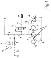
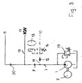
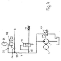
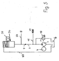
- FIGS. 1 to 5 show various embodiments of control devices, FIGS. 3 and 5 being reference examples, FIG. 6 a delivery volume-speed diagram for the oil supply of conventional motors, and FIG. 7 the delivery volume-speed diagram for the invention
- Control device according to FIGS. 1 and 2 Fig. 8 is a delivery volume-speed diagram for the drive device of FIG. 3
- Fig. 9 is a delivery volume-speed diagram for the drive device according to FIGS. 4 and 5
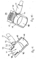
- Fig. 10 a Electromagnetically releasable piston accumulator of the drive device according to FIG. 5, partly in section
- FIG. 11 shows the piston accumulator according to FIG. 10 in axial section.
- the drive device has an oil pump 1 which is connected via a respective clutch 2, 3 to a vehicle engine 4 and an electric motor 5.
- the funded by the oil pump 1 from a tank 6 oil is conveyed via a pressure line 7 to a camshaft adjuster 8, which is formed in a known manner and therefore is not described in detail.
- a camshaft adjuster 8 In the pressure line 7 sits in the direction of the camshaft adjuster 8 opening check valve 9.
- the subsidized via the pressure line 7 oil is also used to supply oil to the camshaft, especially for bearing lubrication.
- Additional consumers 10 may optionally be connected to the pressure line 7, for example automated transmissions, brake booster and the like.
- This consumer 10 is connected via a line 11 to the pressure line 7.
- In the line 11 is seated against the pressure line 7 closing check valve 12.
- a further line 15 is connected in the region between the oil pump 1 and the line 11 to the pressure line 7, in which a pressure switching valve 16 is seated, with the access of the oil supplied from the oil pump 1 to the crankshaft 17 is controlled.
- the pressure-adjusting valve 16 is designed so that the oil flowing in the pressure line 7 only reaches the crankshaft 17 at a certain pressure.
- the check valve 9 is designed so that initially the pressurized oil passes through this check valve 9 to the camshaft adjuster 8 and the camshaft, so that these components are supplied with the necessary oil first. As soon as the pressure in the pressure line 7 has reached a higher value, the pressure-adjusting valve 16 is opened so that the oil can reach the crankshaft 17 via the line 15.
- the electric motor 5 is switched on, the oil pump 1 via the clutch 2 drives.
- the clutch 3 between the oil pump 1 and the vehicle engine 4 is opened at this stage, so that there is a freewheel between the oil pump 1 and the vehicle engine 4.
- the necessary oil is already promoted in the ignition position via the pressure line 7 to the camshaft adjuster 8 and the camshaft in the ignition position.
- the vehicle engine 4 is also driven. Once the vehicle engine 4 has a higher speed than the electric motor 5, the clutch 3 is closed, so that the oil pump 1 is driven in a known manner by the vehicle engine 4.
- the clutch 2 between the oil pump 1 and the electric motor 5 is opened or switched to freewheeling. Now, the oil supply of the camshaft and the camshaft adjuster 8 takes place in a conventional manner.
- the clutch 2 is closed and the electric motor 5 is thus switched on, so that the oil pump 1 is brought back to the necessary rotational speed. With her then the oil can be sufficiently promoted to the camshaft and the camshaft adjuster 8. With the connection of the electric motor 5, the clutch 3 between the oil pump 1 and the vehicle engine 4 is opened or switched to freewheeling.
- a tank line 18 in which a pressure relief valve 19 is seated. As soon as the pressure in the pressure line 7 exceeds a predetermined value, the pressure limiting valve 19 opens, so that the oil can flow back to the tank 6.
- the camshaft and the camshaft adjuster 8 are already supplied with oil when the vehicle engine is not yet switched on.
- a single oil pump 1 is provided for the supply of the camshaft adjuster 8 and any other consumer 10 only a single oil pump 1 is provided.
- the electric motor 5 is switched on as an auxiliary supply when the oil is not conveyed sufficiently in the pressure line 7.
- the drive device has two oil pumps 1, 1 '.
- the oil pump 1 ' is driven in a conventional manner by the vehicle engine 4 and can be made small in size.
- the oil pump 1 is driven by the electric motor 5.
- the electric motor 5 In the ignition position of the ignition key, the electric motor 5, as has been explained with reference to the embodiment of Fig. 1, turned on, so that the oil from the oil pump 1 via the pressure line 7 and the check valve 9 to the camshaft adjuster 8 and the camshaft with sufficient pressure is encouraged.
- the oil pump 1 ' is driven by the vehicle engine 4 in a known manner.
- the electric motor 5 is then switched off, so that the oil is conveyed exclusively via the oil pump 1 and the line 18 into the pressure line 7.
- a line 21 to the pressure line. 7 connected in the line 21 .
- a pressure relief valve 22 which limits the pressure in the pressure line 7 to a predetermined value. If it is exceeded, the pressure limiting valve 22 opens to the tank 6.
- the oil pump 1 ' is connected via a pressure line 23 to the line 18 and to the line 15.
- the pressure limiting valve 19 in the line 18 ensures that the pressure in the pressure line 23 is not too high.
- the pressure line 23 is connected to the line 15 in the area between the pressure switching valve 16 and the crankshaft 17.
- the oil pump 1 ' can be dimensioned small.
- the oil pump 1 ' is always in operation as long as the vehicle engine 4 is running.
- the oil pump 1 ' is then driven speed dependent in a known manner.
- the camshaft adjuster 8 and the camshaft are supplied with oil when the vehicle engine 4 is not yet turned on.
- the oil pump 1 can be switched on as an auxiliary supply when the supply of the camshaft adjuster and the camshaft by the oil pump 1 'should not be sufficient. Since the oil pump 1 'is constantly in operation, the camshaft bearing is lubricated depending on the speed, resulting in an optimal wear behavior.
- Fig. 6 shows the oil supply in a conventional engine.
- the delivery volume of oil is plotted against the speed of the engine.
- Line 24 indicates the oil requirement of the engine. With increasing speed of the engine, the oil consumption increases.
- the line 25 in Fig. 6 shows the delivery volume of the engine oil pump. If the engine is switched off and accordingly the speed is zero, then the oil delivery volume is also zero. When the engine is switched on, the delivery volume increases with the speed approximately linearly. The curve 25 increases much more than the curve 24 at.
- the oil requirement of the engine (curve 24) has a certain value when the engine is switched off. If the vehicle engine is idling, the oil supply to the engine is insufficient.
- the curve 24 in the diagram according to FIG. 6 extends above the delivery volume curve 25 in this region.
- the region 26 between these two curve segments identifies the sub-supply region. Since the oil supply of the engine is not sufficient at idle speed, the bearings of the vehicle engine and the camshaft adjuster must be oversized.
- the delivery volume curve 25 cuts the oil consumption curve 24 at point 27. In this point of intersection 27, the oil supply of the engine is sufficient. However, since the delivery volume curve 25 increases more rapidly with increasing engine speed than the oil consumption curve 24, an oil oversupply is given at higher speeds in the region 28 above the point of intersection 27. It represents a power loss, since such an oversupply would not be necessary for a sufficient oil supply to the engine.
- the control devices according to FIGS. 1 and 2 have a delivery volume-speed diagram, as shown in Fig. 7.
- Fig. 7 are at sub-supply and over-demand areas 26, 28 provided by conventional motors characterized by hatching. Since in the control devices according to FIGS. 1 and 2, the oil pump 1, 1 'are already switched on when the vehicle engine 4 is not yet running, the delivery volume curve 29 is substantially flatter than in conventional engines (FIG. 6). In particular, the delivery volume curve 29 does not run through the zero point of the delivery volume-speed diagram. As is apparent from Fig. 7, the delivery volume curve 29 is substantially flatter than the delivery volume curve 25 in the known engines. Accordingly, the areas 26 ', 28' are substantially smaller than in the known embodiments.
- the drive device has only a single oil pump 1, which is driven by the electric motor 5.
- About the pressure line 7 of the camshaft adjuster 8 and the camshaft is supplied with the necessary oil.
- line 11 is connected to the pressure line 7, via which at least one further consumer 10 is connected.
- the oil reservoir 13 and the Zuschaltventil 14 which is provided in the region between the check valve 12 and the memory 13.
- the pressure in the pressure line 7 is determined by the pressure limiting valve 19.
- an oil pump driven by the vehicle engine is not provided.
- the electric motor 5 is designed in terms of its performance so that the necessary oil supply is ensured for the individual components.
- the electric motor 5 is already operated according to the previous embodiments in the ignition position of the ignition key, so that before starting the vehicle engine, the camshaft adjuster 8, the camshaft and the crankshaft 17 and any other consumers 10 are supplied with the necessary oil.
- optimum efficiency and optimum wear behavior of the bearing are obtained. It can also be used materials with low strength, since the components to be lubricated are supplied with the necessary oil before starting the engine.
- the delivery volume-speed diagram belonging to the reference example according to FIG. 3 is shown in FIG. 8. On it, the undersupply and over-supply regions 26, 28 provided in the conventional motors are characterized by hatching.
- the delivery volume curve 29 of the reference example according to FIG. 3 is shifted to higher delivery volume values in comparison with the activation devices according to FIGS. 1 and 2.
- the areas between the curve 29 and the oil demand curve 24 for the engine are minimized, so that, as in the previous embodiments, a shortage of oil at speeds below the intersection 27 is avoided, while an oversupply of oil at higher speeds also avoided at most only slightly present.
- the drive device has a single oil pump 1, which is actuated exclusively by the vehicle engine 4.
- a single oil pump 1 which is actuated exclusively by the vehicle engine 4.
- an additional memory 31 is used. It is secured against the pressure line 7 by a check valve 32. From the pressure line 7 branches off the line 15, in which the pressure switching valve 16 is located and leading to the crankshaft 17.
- To the pressure line 7 also includes a line 33, in which a closing against the pressure line 7 check valve 34 is located. So that the oil contained in the additional memory 31 can be used, the additional memory 31 is connected to a valve 35.
- the pressure in the pressure line 7 is limited by the pressure limiting valve 19.
- the valve 35 In the ignition position of the ignition key, the valve 35 is opened, so that the oil in the additional memory 31 to the camshaft adjuster 8 and the camshaft can flow. As soon as the engine is started and a corresponding pressure builds up in the pressure line 7, the pressure-adjusting valve 16 is opened, so that the oil can flow to the crankshaft 17 via the line 15. In addition, the oil can pass through the line 33 and the check valve 34 to the camshaft adjuster and to the camshaft.
- the drive device according to FIG. 5 (reference example) essentially corresponds to the exemplary embodiment according to FIG. 4.
- the drive device is provided with a piston accumulator 36, which can be locked with an electromagnet 37. If the ignition position is switched on with the ignition key, the electromagnet 37 is excited so that it releases the piston accumulator 36. He can promote the oil in it via the line 33 to the camshaft adjuster 8 and the camshaft.
- the piston accumulator 36 is connected to the pressure line 7, in which the closing against the oil pump 1 check valve 9 is located.
- the line 33 branches off in the area between the check valve 9 and the piston accumulator 36. In the area between the oil pump 1 and the check valve 9 leading to the crankshaft 17 line 15 is connected to the pressure line 7. According to the previous embodiments, with the pressure relief valve 19, the pressure of the oil in the pressure line 7 limited.
- vent line 38 is connected to the piston accumulator 36.
- the oil pump 1 After unlocking the piston accumulator 36, the oil has been supplied under pressure via the line 33 to the camshaft adjuster 8 and the camshaft, the oil pump 1 is switched on when starting the engine 4, which promotes the necessary oil via the line 15 to the crankshaft 17. In addition, the pressurized oil is conveyed via the check valve 9 in the conduit 33. According to the previous embodiment, the pressure of the oil in the pressure line 7 is so great that the piston accumulator 36 is refilled with oil.
- Fig. 9 shows the delivery volume-speed diagram for the control devices according to FIGS. 4 and 5.
- the curve 25 indicates the delivery volume of the oil pump 1, while the curve 24 indicates the oil requirement of the engine.
- the curve 25 passes through the zero point of the diagram.
- the area 39 hatched in FIG. 9 identifies the storage volume of the additional storage 31 (FIG. 4) or of the piston storage 36 (FIG. 5). As a result, the undersupply region 26 is considerably reduced in comparison to conventional motors (FIG. 6).
- the piston accumulator 36 has, as shown in FIGS. 10 and 11, a cylindrical housing 40 in which a piston 41 is slidably mounted. It is provided on the circumference with an annular groove 42 into which a plunger 43 of the electromagnet 37 can engage. With the ram 43 engaging in the annular groove 42, the piston 41 is locked in a starting position.
- the piston 41 has a diameter-tapered projection 44, which is surrounded by a helical compression spring 45. It is supported at one end on a bottom 46 of the housing 40 and at its other end on a radial shoulder surface 47 of the piston 41 from.
- the piston 41 delimits on the side facing away from the projection 44 a storage space 48 in which the oil is located and into which the pressure line 7 (FIG. 5) opens.
- the helical compression spring 45 is designed such that it displaces the piston 41, which displaces the oil in the storage space 48 into the line 33 (FIG. 5) to the camshaft adjuster 8 or to the camshaft.
- the oil pump 1 conveys oil from the tank 6 via the pressure line 7 into the storage space 48.
- the pressure in the pressure line 7 is greater than the counteracting pressure of the spring 45, so that the piston 41 is pushed back into the position shown in FIGS. 10 and 11, in which it advantageously rests with the projection 44 on the housing bottom 46.
- the electromagnet 37 is switched so that the plunger 43 engages in the annular groove 42 of the piston 41 and secures it in the starting position.
- the control devices described ensure that the camshaft is returned to a defined starting position even before starting the vehicle engine, so that the camshaft adjuster can function properly during the subsequent starting of the engine. As the vehicle engine 4 is only turned on when the control devices have the camshaft adjuster 8 and the camshaft and possibly also the crankshaft 17 already supplied with oil, a trouble-free operation is guaranteed.
- the control devices can be used not only for internal combustion engines, but also for automated transmissions. Due to the described rapid oil pressure build-up, the automated transmission can start early.
Landscapes
- Engineering & Computer Science (AREA)
- General Engineering & Computer Science (AREA)
- Mechanical Engineering (AREA)
- Physics & Mathematics (AREA)
- Fluid Mechanics (AREA)
- Chemical & Material Sciences (AREA)
- Analytical Chemistry (AREA)
- Valve Device For Special Equipments (AREA)
- Lubrication Of Internal Combustion Engines (AREA)
- Auxiliary Drives, Propulsion Controls, And Safety Devices (AREA)
- Control Of Transmission Device (AREA)
- Valve-Gear Or Valve Arrangements (AREA)
Claims (14)
- Dispositif de démarrage pour au moins un déphaseur d'arbre à cames de véhicules automobiles qui présentent un moteur (4) et qui sont munis d'au moins une pompe pour une huile, ladite pompe alimentant le déphaseur d'arbre à cames en huile par l'intermédiaire d'au moins une conduite de compression,
caractérisé en ce que
le dispositif de démarrage alimente le déphaseur d'arbre à cames (8) en huile avant le démarrage du moteur (4) de telle manière que l'huile sous pression accède en premier lieu au déphaseur d'arbre à cames (8) par l'intermédiaire d'un clapet anti-retour (9) avant qu'une soupape de mise en circuit de pression (16) s'ouvre, de manière à ce que l'huile accède à l'arbre à vilebrequin (17) du moteur (4) par l'intermédiaire d'une conduite (15). - Dispositif de démarrage selon la revendication 1,
caractérisé en ce que la pompe (1) peut être actionnée par un moteur électrique (5) qui peut être couplé de manière avantageuse à la pompe (1) par l'intermédiaire d'un accouplement (2). - Dispositif de démarrage selon la revendication 1 ou 2,
caractérisé en ce que la pompe (1, 1') peut être actionnée par le moteur (4). - Dispositif de démarrage selon l'une quelconque des revendications 1 à 3,
caractérisé en ce que la pompe (1) peut être couplée au moteur (4) par l'intermédiaire d'un accouplement (3). - Dispositif de démarrage selon l'une quelconque des revendications 1 à 4,
caractérisé en ce que deux pompes (1, 1') sont prévues, dont la première pompe (1) peut être couplée au moteur électrique (5) et dont l'autre pompe (1') peut être couplée au moteur (4) et en ce que les deux pompes (1, 1') peuvent être couplées alternativement de manière avantageuse. - Dispositif de démarrage selon l'une quelconque des revendications 1 à 5,
caractérisé en ce que l'huile peut être prélevée à partir d'au moins un accumulateur additionnel (31, 36) avant le démarrage du moteur (4). - Dispositif de démarrage selon la revendication 6,
caractérisé en ce qu'une soupape de commande (35) est placée en amont de l'accumulateur additionnel (31). - Dispositif de démarrage selon la revendication 7,
caractérisé en ce que la soupape de commande (35) est raccordée à un allumage du véhicule et est ouverte de manière avantageuse dans la position d'amorçage de l'allumage. - Dispositif de démarrage selon l'une quelconque des revendications 6 à 8,
caractérisé en ce que l'accumulateur additionnel (31, 36) est précontraint. - Dispositif de démarrage selon l'une quelconque des revendications 6 à 9,
caractérisé en ce que l'accumulateur additionnel (36) est un accumulateur à piston qui peut être verrouillé de manière avantageuse dans une position initiale. - Dispositif de démarrage selon la revendication 10,
caractérisé en ce qu'un piston (41) de l'accumulateur à piston (36) présente une rainure annulaire (42) dans laquelle s'engage un élément de blocage (43) réalisé de manière avantageuse sous forme de poussoir d'un électroaimant (37). - Dispositif de démarrage selon la revendication 11,
caractérisé en ce que le piston (41) est précontraint par au moins un ressort de compression (45). - Dispositif de démarrage selon l'une quelconque des revendications 10 à 12,
caractérisé en ce qu'une chambre d'accumulation (48) de l'accumulateur à piston (36) est reliée à la pompe (1) par l'intermédiaire d'au moins une conduite de compression (7). - Dispositif de démarrage selon l'une quelconque des revendications 11 à 13,
caractérisé en ce que l'électroaimant (37) est raccordé à l'allumage du véhicule et est actionné de manière avantageuse dans la position d'amorçage de l'allumage.
Applications Claiming Priority (2)
| Application Number | Priority Date | Filing Date | Title |
|---|---|---|---|
| DE10216352 | 2002-04-13 | ||
| DE10216352A DE10216352A1 (de) | 2002-04-13 | 2002-04-13 | Ansteuereinrichtung für mindestens einen Verbraucher, wie Nockenwellenversteller, automatisches Getriebe und dergleichen, von Fahrzeugen, vorzugsweise Kraftfahrzeugen |
Publications (3)
| Publication Number | Publication Date |
|---|---|
| EP1353075A2 EP1353075A2 (fr) | 2003-10-15 |
| EP1353075A3 EP1353075A3 (fr) | 2004-09-15 |
| EP1353075B1 true EP1353075B1 (fr) | 2007-04-18 |
Family
ID=28051295
Family Applications (1)
| Application Number | Title | Priority Date | Filing Date |
|---|---|---|---|
| EP03007743A Expired - Lifetime EP1353075B1 (fr) | 2002-04-13 | 2003-04-04 | Dispositif de démarrage d'un utilisateur, comme déphaseur d'un arbre à cames, boîte de vitesses automatique et similaire, d'un véhicule, surtout d'un véhicule à moteur |
Country Status (4)
| Country | Link |
|---|---|
| US (1) | US7047931B2 (fr) |
| EP (1) | EP1353075B1 (fr) |
| AT (1) | ATE360148T1 (fr) |
| DE (2) | DE10216352A1 (fr) |
Families Citing this family (45)
| Publication number | Priority date | Publication date | Assignee | Title |
|---|---|---|---|---|
| DE102004061034A1 (de) * | 2004-12-18 | 2006-06-22 | Daimlerchrysler Ag | Verfahren zur Überwachung einer Getriebeölpumpe |
| JP4522906B2 (ja) * | 2005-04-14 | 2010-08-11 | 川崎重工業株式会社 | エンジンの潤滑構造 |
| WO2007107428A2 (fr) | 2006-03-17 | 2007-09-27 | Hydraulik-Ring Gmbh | Circuit hydraulique, destiné en particulier à des dispositifs de réglage d'arbre à cames, et élément de commande correspondant |
| DE102006012733B4 (de) * | 2006-03-17 | 2008-03-27 | Hydraulik-Ring Gmbh | Fast cam phaser-Hydraulikkreis, insbesondere für Nockenwellenversteller, und entsprechendes Steuerelement |
| DE102006012775B4 (de) * | 2006-03-17 | 2008-01-31 | Hydraulik-Ring Gmbh | Fast cam phaser-Hydraulikkreis, insbesondere für Nockenwellenversteller, und entsprechendes Steuerelement |
| ES2339289T3 (es) * | 2006-03-17 | 2010-05-18 | Hydraulik-Ring Gmbh | Circuito hidraulico, en especial para un dispositivo de ajuste de eje de levas, y elemento de control correspondiente. |
| DE102006041899A1 (de) * | 2006-09-07 | 2008-03-27 | Zf Friedrichshafen Ag | Verfahren zum Betätigen einer Hydraulikspeichereinrichtung einer Getriebeeinrichtung |
| DE102007024751A1 (de) * | 2007-05-26 | 2008-11-27 | Bayerische Motoren Werke Aktiengesellschaft | Fahrzeug mit einem Getriebe und einer Ölversorgungseinrichtung zur Versorgung des Getriebes mit Getriebeöl |
| DE102007000620A1 (de) * | 2007-11-05 | 2009-05-07 | Zf Friedrichshafen Ag | Vorrichtung zum Speichern von Hydraulikfluid und Verfahren zum Betreiben einer Vorrichtung zum Speichern von Hydraulikfluid |
| FR2923883B1 (fr) * | 2007-11-16 | 2009-11-20 | Peugeot Citroen Automobiles Sa | Dispositif de pilotage de pompe hydraulique pour une boite de vitesses automatique |
| FR2928326B1 (fr) * | 2008-03-04 | 2012-11-30 | Peugeot Citroen Automobiles Sa | Systeme de freinage avec controle de stabilite et de trajectoire utilisant un dispositif de stockage d'energie ainsi qu'une pompe externe et procede de stockagre denergie associe. |
| DE102008002316A1 (de) * | 2008-06-09 | 2009-12-10 | Robert Bosch Gmbh | Vorrichtung zum Verändern der Drehwinkellage einer Nockenwelle |
| US20100288570A1 (en) * | 2009-05-18 | 2010-11-18 | Gm Global Technology Operations, Inc. | Tandem dual pumps for a hybrid propulsion system |
| DE102009022869A1 (de) * | 2009-05-27 | 2010-12-09 | Hydraulik-Ring Gmbh | Flügelzellennockenwellenverstellersystem |
| DE102009050779B4 (de) | 2009-10-27 | 2016-05-04 | Hilite Germany Gmbh | Schwenkmotornockenwellenversteller mit einer Reibscheibe und Montageverfahren |
| DE102009052841A1 (de) * | 2009-11-13 | 2011-05-19 | Hydraulik-Ring Gmbh | Nockenwelleneinsatz |
| DE102009054054A1 (de) * | 2009-11-20 | 2011-05-26 | Schaeffler Technologies Gmbh & Co. Kg | Montageanordnung und Verfahren zur Montage eines Druckspeichers für Brennkraftmaschinen |
| DE102009054052B4 (de) * | 2009-11-20 | 2018-08-23 | Schaeffler Technologies AG & Co. KG | Schaltbare Vorrichtung zur Druckversorgung |
| DE102010045358A1 (de) | 2010-04-10 | 2011-10-13 | Hydraulik-Ring Gmbh | Schwenkmotornockenwellenversteller mit einem Hydraulikventil |
| DE102010019005B4 (de) | 2010-05-03 | 2017-03-23 | Hilite Germany Gmbh | Schwenkmotorversteller |
| US20120085227A1 (en) * | 2010-10-08 | 2012-04-12 | GM Global Technology Operations LLC | Latching assembly for an accumulator |
| DE102010042189A1 (de) | 2010-10-08 | 2012-04-12 | Robert Bosch Gmbh | Vorrichtung zur Steuerung eines hydraulischen Speichers eines Hydrauliksystems |
| DE102010042194A1 (de) | 2010-10-08 | 2012-04-12 | Robert Bosch Gmbh | Vorrichtung zur Steuerung eines hydraulischen Speichers eines Hydrauliksystems |
| DE102010061337B4 (de) | 2010-12-20 | 2015-07-09 | Hilite Germany Gmbh | Hydraulikventil für einen Schwenkmotorversteller |
| KR101305184B1 (ko) * | 2011-05-04 | 2013-09-12 | 현대자동차주식회사 | 자동차의 열교환 장치 및 열교환 장치 제어방법 |
| DE102011075411A1 (de) | 2011-05-06 | 2012-11-08 | Robert Bosch Gmbh | Getriebe eines Kraftfahrzeugs mit einer Eingangswelle und einer Ausgangswelle |
| DE102011100849A1 (de) * | 2011-05-06 | 2012-11-08 | Audi Ag | Doppelkupplungsgetriebe |
| CN104039682B (zh) * | 2012-01-09 | 2017-04-12 | 伊顿公司 | 用于使用单一输入获得全范围升降速度的方法 |
| WO2013176546A2 (fr) * | 2012-05-23 | 2013-11-28 | Dti Group B.V. | Système hydraulique en particulier pour l'actionnement d'un système de transmission |
| JP6045409B2 (ja) | 2013-03-13 | 2016-12-14 | 日立オートモティブシステムズ株式会社 | オイル供給装置 |
| CN106661868B (zh) | 2014-05-06 | 2019-05-10 | 伊顿公司 | 具有静液选择的液压混合推进回路和操作方法 |
| JP6806409B2 (ja) | 2014-10-27 | 2021-01-06 | イートン コーポレーションEaton Corporation | 静圧オプションを有する油圧ハイブリッド推進回路とその操作方法 |
| DE102015106262B3 (de) * | 2015-04-23 | 2016-09-22 | Hilite Germany Gmbh | Verfahren zum Betreiben einer hydraulisch betriebenen Verstelleranordnung |
| ITUB20153400A1 (it) * | 2015-09-03 | 2017-03-03 | Ferrari Spa | Metodo di controllo di un motore elettrico di un sistema idraulico di una trasmissione in un veicolo |
| DE102016214056B4 (de) * | 2016-07-29 | 2024-06-20 | Zf Friedrichshafen Ag | Vorrichtung zum Speichern von Hydraulikfluid eines Hydrauliksystems eines Automatgetriebes eines Kraftfahrzeugs |
| DE102016216357A1 (de) | 2016-08-30 | 2018-03-01 | Bayerische Motoren Werke Aktiengesellschaft | Antriebseinrichtung für ein Kraftfahrzeug |
| DE102016218835B4 (de) | 2016-09-29 | 2024-10-10 | Ford Global Technologies, Llc | Ölversorgungseinheit und Kraftfahrzeug |
| GB2558214B (en) | 2016-12-22 | 2021-07-21 | Concentric Birmingham Ltd | Auxiliary drive system for a pump |
| US10989052B2 (en) * | 2017-02-14 | 2021-04-27 | Kolberg-Pioneer, Inc. | Apparatus and method for a dual power system |
| DE102020100583A1 (de) * | 2020-01-13 | 2021-07-15 | Schwäbische Hüttenwerke Automotive GmbH | Fluidversorgungssystem zur Versorgung mehrerer Fluidverbraucher eines Kraftfahrzeugs mit Fluid |
| CN111828578B (zh) * | 2020-07-23 | 2021-11-12 | 广东韶钢松山股份有限公司 | 一种调节机构、电液动回转器 |
| EP4240970A4 (fr) * | 2020-11-09 | 2024-10-30 | PDC Machines Inc. | Système d'injection d'huile active pour compresseur à membrane |
| GB2602504B (en) | 2021-01-05 | 2023-03-01 | Concentric Birmingham Ltd | Hybrid pump apparatus |
| US12110960B2 (en) | 2022-03-09 | 2024-10-08 | Deere & Company | Work vehicle drive with solenoid boosted lubrication pump |
| DE102024207740A1 (de) * | 2024-08-14 | 2026-02-19 | Zf Friedrichshafen Ag | Ölversorgungssystem mit elektrischen Zusatzantrieb |
Citations (2)
| Publication number | Priority date | Publication date | Assignee | Title |
|---|---|---|---|---|
| DE3929078A1 (de) * | 1989-09-01 | 1991-03-07 | Blaj Adrian Dipl Ing | Verfahren zur schmierung von brennkraftmaschinen und vorrichtung zur durchfuehrung dieses verfahrens |
| US5589059A (en) * | 1995-06-07 | 1996-12-31 | Semar; James E. | Oil filter adapter system incorporating an accessible filter element |
Family Cites Families (11)
| Publication number | Priority date | Publication date | Assignee | Title |
|---|---|---|---|---|
| FR874863A (fr) * | 1940-07-01 | 1942-08-28 | B M W Flugmotorenbau G M B H | Dispositif pour la lubrification préalable au démarrage de moteurs à combustion interne, notamment sur avions |
| US2393833A (en) * | 1942-01-14 | 1946-01-29 | Wright Aeronautical Corp | Engine lubrication system |
| US4112910A (en) * | 1976-04-23 | 1978-09-12 | Prelube Corporation | Pre-lube device |
| US4875551A (en) * | 1987-10-13 | 1989-10-24 | R. P. M. Industries | Pre-lubricant oil pressure adapter |
| US4840543A (en) * | 1988-08-10 | 1989-06-20 | Geberth John Daniel Jun | Clutch apparatus for rapid power source conversion |
| US4940114A (en) * | 1989-09-05 | 1990-07-10 | Albrecht Kenneth D | Engine prelubricating system |
| ITTO980060A1 (it) * | 1998-01-23 | 1999-07-23 | Fiat Ricerche | Perfezionamenti ai motori a combustione intenra con valvole ad azionam ento variabile. |
| US6148789A (en) * | 1999-02-03 | 2000-11-21 | Johns; Ralph Howard | Engine-pressurized prestart oiler |
| JP2001193661A (ja) * | 1999-06-08 | 2001-07-17 | Denso Corp | 作動油供給システムおよびその制御方法 |
| US6655342B1 (en) * | 2001-04-18 | 2003-12-02 | Antonius G. Wendels | Pre-lubrication system |
| US6871620B2 (en) * | 2002-04-09 | 2005-03-29 | Ford Global Technologies, Llc | Variable cam timing unit oil supply arrangement |
-
2002
- 2002-04-13 DE DE10216352A patent/DE10216352A1/de not_active Withdrawn
-
2003
- 2003-04-04 EP EP03007743A patent/EP1353075B1/fr not_active Expired - Lifetime
- 2003-04-04 DE DE50307049T patent/DE50307049D1/de not_active Expired - Fee Related
- 2003-04-04 AT AT03007743T patent/ATE360148T1/de not_active IP Right Cessation
- 2003-04-11 US US10/249,458 patent/US7047931B2/en not_active Expired - Fee Related
Patent Citations (2)
| Publication number | Priority date | Publication date | Assignee | Title |
|---|---|---|---|---|
| DE3929078A1 (de) * | 1989-09-01 | 1991-03-07 | Blaj Adrian Dipl Ing | Verfahren zur schmierung von brennkraftmaschinen und vorrichtung zur durchfuehrung dieses verfahrens |
| US5589059A (en) * | 1995-06-07 | 1996-12-31 | Semar; James E. | Oil filter adapter system incorporating an accessible filter element |
Also Published As
| Publication number | Publication date |
|---|---|
| US7047931B2 (en) | 2006-05-23 |
| EP1353075A2 (fr) | 2003-10-15 |
| DE10216352A1 (de) | 2003-10-23 |
| DE50307049D1 (de) | 2007-05-31 |
| EP1353075A3 (fr) | 2004-09-15 |
| US20050072397A1 (en) | 2005-04-07 |
| ATE360148T1 (de) | 2007-05-15 |
Similar Documents
| Publication | Publication Date | Title |
|---|---|---|
| EP1353075A2 (fr) | Dispositif de démarrage d'un utilisateur, comme déphaseur d'un arbre à cames, boíte de vitesses automatique et similaire, d'un véhicule, surtout d'un véhicule à moteur | |
| DE10213598B4 (de) | Ölpumpe für eine Brennkraftmaschine und Verfahren zum Betrieb derselben | |
| EP1306548B1 (fr) | Dispositif d'injection de carburant dont le réglage du débit est amélioré | |
| DE102011007605A1 (de) | Ein Ölversorgungssystem für einen Motor | |
| WO2008067935A2 (fr) | Dispositif de réglage | |
| DE102016204399B4 (de) | Hydrauliksystem für ein Getriebe eines Kraftfahrzeugs | |
| DE102012018965A1 (de) | Flügelpumpe | |
| DE19542653C2 (de) | Automatikgetriebe für ein motorbetriebenes Fahrzeug | |
| DE112011105490T5 (de) | Kraftstoffpumpe | |
| EP1985882A1 (fr) | Embrayage à friction hydraulique pour l'entraînement d'un ventilateur dans un véhicule automobile | |
| EP2331797A1 (fr) | Dispositif de réglage variable des temps de commande des soupapes d échange de gaz d un moteur à combustion interne | |
| DE102007013021A1 (de) | Zusatzhydraulikkreis für eine Nockenwellenverstellvorrichtung und Betriebsverfahren | |
| DE102020204675A1 (de) | Pumpen-System mit Kupplungen | |
| DE102007056685A1 (de) | Vorrichtung zur variablen Einstellung der Steuerzeiten von Gaswechselventilen einer Brennkraftmaschine | |
| DE102016010746A1 (de) | Kraftstoffpumpen-Befestigungskonstruktion für einen Motor | |
| EP3848592A1 (fr) | Système d'alimentation en liquide destiné à l'alimentation de plusieurs consommateurs de fluide d'un véhicule automobile en fluide | |
| DE60034005T2 (de) | Brennstoffhochdruckpumpenregelung durch Deaktivierung von Kolben | |
| DE102017202063A1 (de) | Autoschmiermittelpumpsystem mit zweiteiligem Entlastungsventil | |
| EP2977572B1 (fr) | Système de lubrification de paliers d'un moteur à combustion interne d'un véhicule automobile | |
| DE102011104934A1 (de) | Stelleinrichtung zum variablen Einstellen eines Verdichtungsverhältnisses einer Verbrennungskraftmaschine | |
| DE10139055A1 (de) | Verfahren, Computerprogramm, Steuer- und/oder Regelgerät sowie Kraftstoffsystem für eine Brennkraftmaschine | |
| DE102004029706A1 (de) | Ölversorgungssystem und Verfahren mit Vorrangsteuerug | |
| DE102008002480A1 (de) | Hydraulikeinrichtung zum Verändern der Drehwinkellage einer Nockenwelle | |
| DE3814750A1 (de) | Einrichtung zum antrieb einer schmiermittelpumpe einer brennkraftmaschine | |
| DE19702381A1 (de) | Servolenkeinheit für ein Fahrzeug |
Legal Events
| Date | Code | Title | Description |
|---|---|---|---|
| PUAI | Public reference made under article 153(3) epc to a published international application that has entered the european phase |
Free format text: ORIGINAL CODE: 0009012 |
|
| AK | Designated contracting states |
Kind code of ref document: A2 Designated state(s): AT BE BG CH CY CZ DE DK EE ES FI FR GB GR HU IE IT LI LU MC NL PT RO SE SI SK TR |
|
| AX | Request for extension of the european patent |
Extension state: AL LT LV MK |
|
| PUAL | Search report despatched |
Free format text: ORIGINAL CODE: 0009013 |
|
| AK | Designated contracting states |
Kind code of ref document: A3 Designated state(s): AT BE BG CH CY CZ DE DK EE ES FI FR GB GR HU IE IT LI LU MC NL PT RO SE SI SK TR |
|
| AX | Request for extension of the european patent |
Extension state: AL LT LV MK |
|
| RIC1 | Information provided on ipc code assigned before grant |
Ipc: 7F 01M 5/02 B Ipc: 7F 16H 57/04 B Ipc: 7F 16H 61/00 B Ipc: 7F 15B 20/00 B Ipc: 7F 01L 1/34 B Ipc: 7F 15B 1/26 A |
|
| 17P | Request for examination filed |
Effective date: 20041113 |
|
| AKX | Designation fees paid |
Designated state(s): AT BE BG CH CY CZ DE DK EE ES FI FR GB GR HU IE IT LI LU MC NL PT RO SE SI SK TR |
|
| 17Q | First examination report despatched |
Effective date: 20050428 |
|
| RAP1 | Party data changed (applicant data changed or rights of an application transferred) |
Owner name: HYDRAULIK-RING GMBH |
|
| GRAP | Despatch of communication of intention to grant a patent |
Free format text: ORIGINAL CODE: EPIDOSNIGR1 |
|
| GRAC | Information related to communication of intention to grant a patent modified |
Free format text: ORIGINAL CODE: EPIDOSCIGR1 |
|
| GRAS | Grant fee paid |
Free format text: ORIGINAL CODE: EPIDOSNIGR3 |
|
| GRAA | (expected) grant |
Free format text: ORIGINAL CODE: 0009210 |
|
| AK | Designated contracting states |
Kind code of ref document: B1 Designated state(s): AT BE BG CH CY CZ DE DK EE ES FI FR GB GR HU IE IT LI LU MC NL PT RO SE SI SK TR |
|
| PG25 | Lapsed in a contracting state [announced via postgrant information from national office to epo] |
Ref country code: FI Free format text: LAPSE BECAUSE OF FAILURE TO SUBMIT A TRANSLATION OF THE DESCRIPTION OR TO PAY THE FEE WITHIN THE PRESCRIBED TIME-LIMIT Effective date: 20070418 Ref country code: SI Free format text: LAPSE BECAUSE OF FAILURE TO SUBMIT A TRANSLATION OF THE DESCRIPTION OR TO PAY THE FEE WITHIN THE PRESCRIBED TIME-LIMIT Effective date: 20070418 |
|
| REG | Reference to a national code |
Ref country code: CH Ref legal event code: EP |
|
| REG | Reference to a national code |
Ref country code: IE Ref legal event code: FG4D Free format text: LANGUAGE OF EP DOCUMENT: GERMAN |
|
| REF | Corresponds to: |
Ref document number: 50307049 Country of ref document: DE Date of ref document: 20070531 Kind code of ref document: P |
|
| PG25 | Lapsed in a contracting state [announced via postgrant information from national office to epo] |
Ref country code: SE Free format text: LAPSE BECAUSE OF FAILURE TO SUBMIT A TRANSLATION OF THE DESCRIPTION OR TO PAY THE FEE WITHIN THE PRESCRIBED TIME-LIMIT Effective date: 20070718 |
|
| PG25 | Lapsed in a contracting state [announced via postgrant information from national office to epo] |
Ref country code: ES Free format text: LAPSE BECAUSE OF FAILURE TO SUBMIT A TRANSLATION OF THE DESCRIPTION OR TO PAY THE FEE WITHIN THE PRESCRIBED TIME-LIMIT Effective date: 20070729 |
|
| PG25 | Lapsed in a contracting state [announced via postgrant information from national office to epo] |
Ref country code: PT Free format text: LAPSE BECAUSE OF FAILURE TO SUBMIT A TRANSLATION OF THE DESCRIPTION OR TO PAY THE FEE WITHIN THE PRESCRIBED TIME-LIMIT Effective date: 20070918 |
|
| ET | Fr: translation filed | ||
| NLV1 | Nl: lapsed or annulled due to failure to fulfill the requirements of art. 29p and 29m of the patents act | ||
| GBV | Gb: ep patent (uk) treated as always having been void in accordance with gb section 77(7)/1977 [no translation filed] |
Effective date: 20070418 |
|
| REG | Reference to a national code |
Ref country code: IE Ref legal event code: FD4D |
|
| PG25 | Lapsed in a contracting state [announced via postgrant information from national office to epo] |
Ref country code: CZ Free format text: LAPSE BECAUSE OF FAILURE TO SUBMIT A TRANSLATION OF THE DESCRIPTION OR TO PAY THE FEE WITHIN THE PRESCRIBED TIME-LIMIT Effective date: 20070418 Ref country code: BG Free format text: LAPSE BECAUSE OF FAILURE TO SUBMIT A TRANSLATION OF THE DESCRIPTION OR TO PAY THE FEE WITHIN THE PRESCRIBED TIME-LIMIT Effective date: 20070718 Ref country code: IE Free format text: LAPSE BECAUSE OF FAILURE TO SUBMIT A TRANSLATION OF THE DESCRIPTION OR TO PAY THE FEE WITHIN THE PRESCRIBED TIME-LIMIT Effective date: 20070418 Ref country code: NL Free format text: LAPSE BECAUSE OF FAILURE TO SUBMIT A TRANSLATION OF THE DESCRIPTION OR TO PAY THE FEE WITHIN THE PRESCRIBED TIME-LIMIT Effective date: 20070418 Ref country code: DK Free format text: LAPSE BECAUSE OF FAILURE TO SUBMIT A TRANSLATION OF THE DESCRIPTION OR TO PAY THE FEE WITHIN THE PRESCRIBED TIME-LIMIT Effective date: 20070418 |
|
| PLBE | No opposition filed within time limit |
Free format text: ORIGINAL CODE: 0009261 |
|
| STAA | Information on the status of an ep patent application or granted ep patent |
Free format text: STATUS: NO OPPOSITION FILED WITHIN TIME LIMIT |
|
| PG25 | Lapsed in a contracting state [announced via postgrant information from national office to epo] |
Ref country code: SK Free format text: LAPSE BECAUSE OF FAILURE TO SUBMIT A TRANSLATION OF THE DESCRIPTION OR TO PAY THE FEE WITHIN THE PRESCRIBED TIME-LIMIT Effective date: 20070418 |
|
| 26N | No opposition filed |
Effective date: 20080121 |
|
| PG25 | Lapsed in a contracting state [announced via postgrant information from national office to epo] |
Ref country code: IT Free format text: LAPSE BECAUSE OF FAILURE TO SUBMIT A TRANSLATION OF THE DESCRIPTION OR TO PAY THE FEE WITHIN THE PRESCRIBED TIME-LIMIT Effective date: 20070418 Ref country code: GB Free format text: LAPSE BECAUSE OF FAILURE TO SUBMIT A TRANSLATION OF THE DESCRIPTION OR TO PAY THE FEE WITHIN THE PRESCRIBED TIME-LIMIT Effective date: 20070418 Ref country code: GR Free format text: LAPSE BECAUSE OF FAILURE TO SUBMIT A TRANSLATION OF THE DESCRIPTION OR TO PAY THE FEE WITHIN THE PRESCRIBED TIME-LIMIT Effective date: 20070719 |
|
| PG25 | Lapsed in a contracting state [announced via postgrant information from national office to epo] |
Ref country code: RO Free format text: LAPSE BECAUSE OF FAILURE TO SUBMIT A TRANSLATION OF THE DESCRIPTION OR TO PAY THE FEE WITHIN THE PRESCRIBED TIME-LIMIT Effective date: 20070418 |
|
| BERE | Be: lapsed |
Owner name: HYDRAULIK-RING G.M.B.H. Effective date: 20080430 |
|
| PG25 | Lapsed in a contracting state [announced via postgrant information from national office to epo] |
Ref country code: MC Free format text: LAPSE BECAUSE OF NON-PAYMENT OF DUE FEES Effective date: 20080430 |
|
| REG | Reference to a national code |
Ref country code: CH Ref legal event code: PL |
|
| PG25 | Lapsed in a contracting state [announced via postgrant information from national office to epo] |
Ref country code: LI Free format text: LAPSE BECAUSE OF NON-PAYMENT OF DUE FEES Effective date: 20080430 Ref country code: CH Free format text: LAPSE BECAUSE OF NON-PAYMENT OF DUE FEES Effective date: 20080430 Ref country code: DE Free format text: LAPSE BECAUSE OF NON-PAYMENT OF DUE FEES Effective date: 20081101 Ref country code: EE Free format text: LAPSE BECAUSE OF FAILURE TO SUBMIT A TRANSLATION OF THE DESCRIPTION OR TO PAY THE FEE WITHIN THE PRESCRIBED TIME-LIMIT Effective date: 20070418 |
|
| REG | Reference to a national code |
Ref country code: FR Ref legal event code: ST Effective date: 20081231 |
|
| PG25 | Lapsed in a contracting state [announced via postgrant information from national office to epo] |
Ref country code: BE Free format text: LAPSE BECAUSE OF NON-PAYMENT OF DUE FEES Effective date: 20080430 |
|
| PG25 | Lapsed in a contracting state [announced via postgrant information from national office to epo] |
Ref country code: FR Free format text: LAPSE BECAUSE OF NON-PAYMENT OF DUE FEES Effective date: 20080430 |
|
| PG25 | Lapsed in a contracting state [announced via postgrant information from national office to epo] |
Ref country code: CY Free format text: LAPSE BECAUSE OF FAILURE TO SUBMIT A TRANSLATION OF THE DESCRIPTION OR TO PAY THE FEE WITHIN THE PRESCRIBED TIME-LIMIT Effective date: 20070418 |
|
| PG25 | Lapsed in a contracting state [announced via postgrant information from national office to epo] |
Ref country code: AT Free format text: LAPSE BECAUSE OF NON-PAYMENT OF DUE FEES Effective date: 20080404 |
|
| PG25 | Lapsed in a contracting state [announced via postgrant information from national office to epo] |
Ref country code: LU Free format text: LAPSE BECAUSE OF NON-PAYMENT OF DUE FEES Effective date: 20080404 Ref country code: HU Free format text: LAPSE BECAUSE OF FAILURE TO SUBMIT A TRANSLATION OF THE DESCRIPTION OR TO PAY THE FEE WITHIN THE PRESCRIBED TIME-LIMIT Effective date: 20071019 |
|
| PG25 | Lapsed in a contracting state [announced via postgrant information from national office to epo] |
Ref country code: TR Free format text: LAPSE BECAUSE OF FAILURE TO SUBMIT A TRANSLATION OF THE DESCRIPTION OR TO PAY THE FEE WITHIN THE PRESCRIBED TIME-LIMIT Effective date: 20070418 |