EP1353120A2 - Dispositif à enclenchement à diode électroluminescente de véhicle automobile - Google Patents
Dispositif à enclenchement à diode électroluminescente de véhicle automobile Download PDFInfo
- Publication number
- EP1353120A2 EP1353120A2 EP03008148A EP03008148A EP1353120A2 EP 1353120 A2 EP1353120 A2 EP 1353120A2 EP 03008148 A EP03008148 A EP 03008148A EP 03008148 A EP03008148 A EP 03008148A EP 1353120 A2 EP1353120 A2 EP 1353120A2
- Authority
- EP
- European Patent Office
- Prior art keywords
- lamp
- coupler
- heat
- adapter
- base
- Prior art date
- Legal status (The legal status is an assumption and is not a legal conclusion. Google has not performed a legal analysis and makes no representation as to the accuracy of the status listed.)
- Withdrawn
Links
Images




Classifications
-
- F—MECHANICAL ENGINEERING; LIGHTING; HEATING; WEAPONS; BLASTING
- F21—LIGHTING
- F21S—NON-PORTABLE LIGHTING DEVICES; SYSTEMS THEREOF; VEHICLE LIGHTING DEVICES SPECIALLY ADAPTED FOR VEHICLE EXTERIORS
- F21S41/00—Illuminating devices specially adapted for vehicle exteriors, e.g. headlamps
- F21S41/10—Illuminating devices specially adapted for vehicle exteriors, e.g. headlamps characterised by the light source
- F21S41/14—Illuminating devices specially adapted for vehicle exteriors, e.g. headlamps characterised by the light source characterised by the type of light source
- F21S41/141—Light emitting diodes [LED]
-
- F—MECHANICAL ENGINEERING; LIGHTING; HEATING; WEAPONS; BLASTING
- F21—LIGHTING
- F21S—NON-PORTABLE LIGHTING DEVICES; SYSTEMS THEREOF; VEHICLE LIGHTING DEVICES SPECIALLY ADAPTED FOR VEHICLE EXTERIORS
- F21S41/00—Illuminating devices specially adapted for vehicle exteriors, e.g. headlamps
- F21S41/10—Illuminating devices specially adapted for vehicle exteriors, e.g. headlamps characterised by the light source
- F21S41/14—Illuminating devices specially adapted for vehicle exteriors, e.g. headlamps characterised by the light source characterised by the type of light source
- F21S41/141—Light emitting diodes [LED]
- F21S41/147—Light emitting diodes [LED] the main emission direction of the LED being angled to the optical axis of the illuminating device
-
- F—MECHANICAL ENGINEERING; LIGHTING; HEATING; WEAPONS; BLASTING
- F21—LIGHTING
- F21K—NON-ELECTRIC LIGHT SOURCES USING LUMINESCENCE; LIGHT SOURCES USING ELECTROCHEMILUMINESCENCE; LIGHT SOURCES USING CHARGES OF COMBUSTIBLE MATERIAL; LIGHT SOURCES USING SEMICONDUCTOR DEVICES AS LIGHT-GENERATING ELEMENTS; LIGHT SOURCES NOT OTHERWISE PROVIDED FOR
- F21K9/00—Light sources using semiconductor devices as light-generating elements, e.g. using light-emitting diodes [LED] or lasers
- F21K9/20—Light sources comprising attachment means
- F21K9/23—Retrofit light sources for lighting devices with a single fitting for each light source, e.g. for substitution of incandescent lamps with bayonet or threaded fittings
-
- F—MECHANICAL ENGINEERING; LIGHTING; HEATING; WEAPONS; BLASTING
- F21—LIGHTING
- F21S—NON-PORTABLE LIGHTING DEVICES; SYSTEMS THEREOF; VEHICLE LIGHTING DEVICES SPECIALLY ADAPTED FOR VEHICLE EXTERIORS
- F21S41/00—Illuminating devices specially adapted for vehicle exteriors, e.g. headlamps
- F21S41/10—Illuminating devices specially adapted for vehicle exteriors, e.g. headlamps characterised by the light source
- F21S41/19—Attachment of light sources or lamp holders
- F21S41/194—Bayonet attachments
-
- F—MECHANICAL ENGINEERING; LIGHTING; HEATING; WEAPONS; BLASTING
- F21—LIGHTING
- F21S—NON-PORTABLE LIGHTING DEVICES; SYSTEMS THEREOF; VEHICLE LIGHTING DEVICES SPECIALLY ADAPTED FOR VEHICLE EXTERIORS
- F21S41/00—Illuminating devices specially adapted for vehicle exteriors, e.g. headlamps
- F21S41/30—Illuminating devices specially adapted for vehicle exteriors, e.g. headlamps characterised by reflectors
-
- F—MECHANICAL ENGINEERING; LIGHTING; HEATING; WEAPONS; BLASTING
- F21—LIGHTING
- F21S—NON-PORTABLE LIGHTING DEVICES; SYSTEMS THEREOF; VEHICLE LIGHTING DEVICES SPECIALLY ADAPTED FOR VEHICLE EXTERIORS
- F21S43/00—Signalling devices specially adapted for vehicle exteriors, e.g. brake lamps, direction indicator lights or reversing lights
- F21S43/10—Signalling devices specially adapted for vehicle exteriors, e.g. brake lamps, direction indicator lights or reversing lights characterised by the light source
- F21S43/13—Signalling devices specially adapted for vehicle exteriors, e.g. brake lamps, direction indicator lights or reversing lights characterised by the light source characterised by the type of light source
- F21S43/14—Light emitting diodes [LED]
-
- F—MECHANICAL ENGINEERING; LIGHTING; HEATING; WEAPONS; BLASTING
- F21—LIGHTING
- F21S—NON-PORTABLE LIGHTING DEVICES; SYSTEMS THEREOF; VEHICLE LIGHTING DEVICES SPECIALLY ADAPTED FOR VEHICLE EXTERIORS
- F21S43/00—Signalling devices specially adapted for vehicle exteriors, e.g. brake lamps, direction indicator lights or reversing lights
- F21S43/10—Signalling devices specially adapted for vehicle exteriors, e.g. brake lamps, direction indicator lights or reversing lights characterised by the light source
- F21S43/19—Attachment of light sources or lamp holders
-
- F—MECHANICAL ENGINEERING; LIGHTING; HEATING; WEAPONS; BLASTING
- F21—LIGHTING
- F21S—NON-PORTABLE LIGHTING DEVICES; SYSTEMS THEREOF; VEHICLE LIGHTING DEVICES SPECIALLY ADAPTED FOR VEHICLE EXTERIORS
- F21S45/00—Arrangements within vehicle lighting devices specially adapted for vehicle exteriors, for purposes other than emission or distribution of light
- F21S45/10—Protection of lighting devices
-
- F—MECHANICAL ENGINEERING; LIGHTING; HEATING; WEAPONS; BLASTING
- F21—LIGHTING
- F21S—NON-PORTABLE LIGHTING DEVICES; SYSTEMS THEREOF; VEHICLE LIGHTING DEVICES SPECIALLY ADAPTED FOR VEHICLE EXTERIORS
- F21S45/00—Arrangements within vehicle lighting devices specially adapted for vehicle exteriors, for purposes other than emission or distribution of light
- F21S45/40—Cooling of lighting devices
- F21S45/47—Passive cooling, e.g. using fins, thermal conductive elements or openings
-
- F—MECHANICAL ENGINEERING; LIGHTING; HEATING; WEAPONS; BLASTING
- F21—LIGHTING
- F21S—NON-PORTABLE LIGHTING DEVICES; SYSTEMS THEREOF; VEHICLE LIGHTING DEVICES SPECIALLY ADAPTED FOR VEHICLE EXTERIORS
- F21S45/00—Arrangements within vehicle lighting devices specially adapted for vehicle exteriors, for purposes other than emission or distribution of light
- F21S45/40—Cooling of lighting devices
- F21S45/47—Passive cooling, e.g. using fins, thermal conductive elements or openings
- F21S45/48—Passive cooling, e.g. using fins, thermal conductive elements or openings with means for conducting heat from the inside to the outside of the lighting devices, e.g. with fins on the outer surface of the lighting device
-
- F—MECHANICAL ENGINEERING; LIGHTING; HEATING; WEAPONS; BLASTING
- F21—LIGHTING
- F21S—NON-PORTABLE LIGHTING DEVICES; SYSTEMS THEREOF; VEHICLE LIGHTING DEVICES SPECIALLY ADAPTED FOR VEHICLE EXTERIORS
- F21S45/00—Arrangements within vehicle lighting devices specially adapted for vehicle exteriors, for purposes other than emission or distribution of light
- F21S45/50—Waterproofing
-
- F—MECHANICAL ENGINEERING; LIGHTING; HEATING; WEAPONS; BLASTING
- F21—LIGHTING
- F21V—FUNCTIONAL FEATURES OR DETAILS OF LIGHTING DEVICES OR SYSTEMS THEREOF; STRUCTURAL COMBINATIONS OF LIGHTING DEVICES WITH OTHER ARTICLES, NOT OTHERWISE PROVIDED FOR
- F21V29/00—Protecting lighting devices from thermal damage; Cooling or heating arrangements specially adapted for lighting devices or systems
- F21V29/50—Cooling arrangements
- F21V29/70—Cooling arrangements characterised by passive heat-dissipating elements, e.g. heat-sinks
- F21V29/74—Cooling arrangements characterised by passive heat-dissipating elements, e.g. heat-sinks with fins or blades
- F21V29/76—Cooling arrangements characterised by passive heat-dissipating elements, e.g. heat-sinks with fins or blades with essentially identical parallel planar fins or blades, e.g. with comb-like cross-section
-
- F—MECHANICAL ENGINEERING; LIGHTING; HEATING; WEAPONS; BLASTING
- F21—LIGHTING
- F21V—FUNCTIONAL FEATURES OR DETAILS OF LIGHTING DEVICES OR SYSTEMS THEREOF; STRUCTURAL COMBINATIONS OF LIGHTING DEVICES WITH OTHER ARTICLES, NOT OTHERWISE PROVIDED FOR
- F21V29/00—Protecting lighting devices from thermal damage; Cooling or heating arrangements specially adapted for lighting devices or systems
- F21V29/50—Cooling arrangements
- F21V29/70—Cooling arrangements characterised by passive heat-dissipating elements, e.g. heat-sinks
- F21V29/80—Cooling arrangements characterised by passive heat-dissipating elements, e.g. heat-sinks with pins or wires
-
- F—MECHANICAL ENGINEERING; LIGHTING; HEATING; WEAPONS; BLASTING
- F21—LIGHTING
- F21V—FUNCTIONAL FEATURES OR DETAILS OF LIGHTING DEVICES OR SYSTEMS THEREOF; STRUCTURAL COMBINATIONS OF LIGHTING DEVICES WITH OTHER ARTICLES, NOT OTHERWISE PROVIDED FOR
- F21V29/00—Protecting lighting devices from thermal damage; Cooling or heating arrangements specially adapted for lighting devices or systems
- F21V29/50—Cooling arrangements
- F21V29/70—Cooling arrangements characterised by passive heat-dissipating elements, e.g. heat-sinks
- F21V29/83—Cooling arrangements characterised by passive heat-dissipating elements, e.g. heat-sinks the elements having apertures, ducts or channels, e.g. heat radiation holes
-
- F—MECHANICAL ENGINEERING; LIGHTING; HEATING; WEAPONS; BLASTING
- F21—LIGHTING
- F21V—FUNCTIONAL FEATURES OR DETAILS OF LIGHTING DEVICES OR SYSTEMS THEREOF; STRUCTURAL COMBINATIONS OF LIGHTING DEVICES WITH OTHER ARTICLES, NOT OTHERWISE PROVIDED FOR
- F21V31/00—Gas-tight or water-tight arrangements
-
- F—MECHANICAL ENGINEERING; LIGHTING; HEATING; WEAPONS; BLASTING
- F21—LIGHTING
- F21W—INDEXING SCHEME ASSOCIATED WITH SUBCLASSES F21K, F21L, F21S and F21V, RELATING TO USES OR APPLICATIONS OF LIGHTING DEVICES OR SYSTEMS
- F21W2102/00—Exterior vehicle lighting devices for illuminating purposes
-
- F—MECHANICAL ENGINEERING; LIGHTING; HEATING; WEAPONS; BLASTING
- F21—LIGHTING
- F21Y—INDEXING SCHEME ASSOCIATED WITH SUBCLASSES F21K, F21L, F21S and F21V, RELATING TO THE FORM OR THE KIND OF THE LIGHT SOURCES OR OF THE COLOUR OF THE LIGHT EMITTED
- F21Y2105/00—Planar light sources
- F21Y2105/10—Planar light sources comprising a two-dimensional [2D] array of point-like light-generating elements
-
- F—MECHANICAL ENGINEERING; LIGHTING; HEATING; WEAPONS; BLASTING
- F21—LIGHTING
- F21Y—INDEXING SCHEME ASSOCIATED WITH SUBCLASSES F21K, F21L, F21S and F21V, RELATING TO THE FORM OR THE KIND OF THE LIGHT SOURCES OR OF THE COLOUR OF THE LIGHT EMITTED
- F21Y2115/00—Light-generating elements of semiconductor light sources
- F21Y2115/10—Light-emitting diodes [LED]
Definitions
- the invention relates to electric lamps and particularly to automotive lamps. More particularly the invention is concerned with a snap together automotive LED lamp assembly.
- LEDs Light emitting diodes
- the life and efficiency of an LED is related to its temperature of operation. LEDs are therefore frequently mounted singularly, in dispersed groups to reduce any local concentration of heat. Alternatively, they may be operated at less then maximum power to generate less heat. Heat reduction becomes a more significant factor when high power LED's are used. While high power LEDs can generate more absolute light, there is also more absolute heat. In generating a beam of light, such as in exterior automotive lighting, it is convenient to concentrate the light source at or near a single point.
- the concentrated light source can then supply a prescribed reflector or lens assembly to direct light in a prescribed manner to the field to be illuminated.
- concentrating the LEDs at or near a single point generates a correspondingly concentrated supply of heat that works against the life and efficiency of the LEDs.
- a replaceable vehicle lamp assemble may be made with an LED light source mounted on a thermally conductive structure joined to a heat-sinking element exposed to exterior air.
- a mechanical coupler for detachable mounting to a housing or reflector, the coupler generally faces the light source, and supports the thermally conductive structure.
- the coupler supports an electrical connector, and electrical connections extend from the electrical connector to the LED light source to form a replaceable lamp.
- FIG. 1 shows a perspective view of an LED lamp assembly 10 with a portion of a reflector 84, and the end sleeve 22 of a standard automotive electrical coupler.
- FIG. 2 shows a perspective view of an LED lamp assembly 10 without the reflector portion or end sleeve 22.
- FIG. 2 then shows a replaceable lamp unit.
- FIG. 3 shows a cross sectional view of an LED lamp assembly 10 with part of a reflector 84.
- a replaceable vehicle lamp assemble 10 can be formed with a base 12, a coupler 26, adapter 40, and lamp 62.
- the preferred base 12 is molded from plastic resin and has a first wall 14 defining a recess that acts as first receptacle 16 for electrical connection.
- a second wall 18 defines a recess formed to act as a second receptacle 20.
- the interior surface of the second receptacle 20 includes a latching feature 22.
- the latching feature 22 may be a protrusion, or a recess according to design choice.
- the preferred latching feature 22 is an upstanding post extending from the second wall 18.
- the base 12 includes at least one electrical connection 24 that extends from the first receptacle 16 to the second receptacle 20.
- the preferred electrical connection structure comprises two lugs molded in the plastic base. The lugs may be used as plug connectors in the first receptacle 16, and as weld points in the second receptacle 20.
- FIG. 4 shows a perspective view of a coupler 26.
- the coupler 26 generally has a tubular portion 28 with an interior wall 30 defining a central passage 32. Extending from the tubular portion 28 is a first latching feature, such as a first arm 34 that is sized and shaped to cooperatively latch to the latching feature 22 in the base 12.
- the base 12 and coupler 26 are formed to fit snuggly one to the other along adjacent surfaces. The base 12 and the coupler 26 may then be snapped together, mating the base latching feature 22 and the coupler's first latching feature, such as the first arm 34.
- the base 12 and couple 26 may also be keyed one to the other for proper orientation.
- the preferred coupler 26 additionally includes a second latching feature to detachably couple to a housing or reflector opening.
- the lamp assembly may then be replaceably joined to a housing or reflector.
- the preferred second latching feature is one or more second arm(s) 36 supporting axially facing camming face(s) 38.
- the preferred coupler 26 then has a bayonet coupling with several bayonet arms having camming surfaces to mate in a reflector opening.
- the second arm 36 or arms as the case may extend radially relative to the tubular portion 28.
- the coupler 26 can then rotationally latch td a housing or reflector assembly.
- FIG. 5 shows a perspective view of a preferred base coupled to a preferred coupler without the adapter.
- FIG. 5 exposes the coupling relation between the base 12 and coupler 26 while excluding the flange 52 and reflector 84 portions.
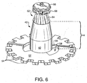
- FIG. 6 shows an upper perspective view of an adapter 40 and a lamp 62.
- the preferred adapter 40 has a tubular portion 42 with an axial dimension 44 directed away from the base 12. The axial dimension 44 may be conveniently set for optical design purposes.
- the adapter 40 also has an exterior wall 46, and an interior wall 48 defining an internal passage 50.
- the tubular portion is designed to have good thermal conductivity, and is thermally connected to a thermally conductive piece with a surface exposed to air on the exterior of the lamp assembly. The pieces should allow substantial heat (10%??? or more of the heat generated from the LED). Alternatively a reduction in LED operating temperature of ??? degrees Celsius is considered substantial.
- the exposed surface is a metal sheet portion exposed on two sides to exterior air.
- a flange 52 extending radially from the tubular portion 42 is a flange 52.
- the flange 52 has the form of a disk extending radially away from the axis of the tubular portion 42.
- the preferred flange 52 includes radiation or airflow features such as extended fingers, holes, flutes, ribs, or similar heat dissipating features as known in the art. Extended fingers 54 are shown as an example. Extending the flange 52 edge to where air currents are likely is suggested.
- the preferred adapter 40, including the flange 52 is formed from a material with high heat conductivity. Copper, die cast aluminum, or zinc or similar metals and constructions maybe used to form the adapter 40 and flange 52 structures, either as a single body, or as coupled pieces.
- the flange 52 is further formed with a wall 56 defining a coupling passage 58.
- the coupling passage 58 is sized and shaped to permit the insertion and passage of at least a portion of the first arm 34 of the coupler 26.
- the central passage 32 of the coupler 26 may be sized and shaped to snuggly fit over the tubular portion 42 of the adapter 40.
- the tubular portion 30 of the coupler 26 is then positioned around the adapter 40, so the first arm 34 of the coupler 26 extends through the coupling passage 58. With the coupler 26 and the adapter 40 locked together, the first latch arm 34 is inserted into second receptacle 20 to latch with the base 12.
- the adapter 40 including the flange 52, is then trapped between the base 12 and the coupler 26.
- FIG. 7 shows a lower perspective view of a coupler 26, adapter 40 and a lamp 62.
- the coupler 26 encircles the adapter 40, and two first arms 34 extend through two coupling passages 58 ready to be coupled in the base 12.
- the coupler 26 and flange 52 may be formed so that the two rotationally latch one to the other while the first coupler arm 34 extends through the coupling passage 58. This can be done with a bayonet like latch.
- a compressible seal 60 may be positioned between the base 12 and the adapter 40, such as along the flange 52.
- An O-ring or flat ring may be held in a groove formed in either the base 12 or the flange 52 as the case may be to encircle the passage for the electrical connections to the LED light source. Sealing may otherwise be completed as known in the art.
- the LED lamp 62 is supported on a distal end of the adapter 40.
- the lamp 62 may comprise a lamp body 64 and an LED holder 66 supporting one or more LEDs 68.
- At least one electrical, but preferably two electrical connections 70, 72 extend from the LEDs through the internal passage 50 of the adapter 40, the internal passage 32 of the coupler 26 to connect with the electrical connector 24 or connectors, as the case may be in the second receptacle 20.
- the adapter 40 and the lamp body 64 are mounted one to another.
- the preferred adapter 40 and the lamp body 64 include corresponding adjacent and conformal surfaces that may be butted one to the other for secure and accurate positioning of the lamp 62 and for good thermal conduction from the lamp 62 to the adapter 40.
- the surfaces may be closely fitting interior and exterior surfaces 74, 76 enabling an axial coupling between the adapter 40 and the lamp 62.
- a telescoping coupling is shown, but a threaded or similar coupling could be used.
- the adapter 40 and the lamp 62 may be soldiered, glued or similarly joined along the adjacent surfaces to enhance positioning or thermal conduction. The abutting coupling then provides a thermally conductive path between the two pieces.
- the preferred adapter 40 and the adjacent lamp 62 surfaces are respectively formed from materials with high heat conductivities, such as copper, aluminum, zinc or other metals. In combination they provide a good heat conductive path from the lamp 62 to the adapter 40 and flange 52 where the heat may be exhausted on the exterior side of the lamp assembly.
- FIG. 8 shows a lamp 62 mounted with LEDs 68.
- the preferred lamp 62 supports a population of LEDs and appropriate electrical circuitry.
- the majority of the LEDs face away from, or only indirectly face the field to be illuminated. This preferred orientation is to prevent direct viewing of the intense light sources by a human.
- the LED's 68 may be mounted on flex material 80 that is then bent over the mushroom like head of the lamp structure to generally face the reflector. Once the LED's are mounted on the lamp head, they may be coated with a clear, protective coating 82 as is known in the art.
- the lamp assembly is coordinated to function with a reflector.
- the assembly may be latched to a reflector 84 by way of the camming surfaces or bayonet arms of the coupler.
- the reflector 84 may be held to the assembly 10 by the coupler 26 using at least in part by the camming face 38 of the coupler 26.
- An exterior wall of the coupler 26 or of the adapters 40 may be used to help locate and position the lamp assembly 10 with respect to the reflector 84.
- An O-ring or flat seal 86 may be positioned between the reflector 84 or general lamp housing as the case may be and a convenient portion of the lamp assembly, such as one side of the flange. The seal 86 then encircles lamp assembly including the heat conducting structure to help prevent dirt and water from affecting the reflector or lamp housing.
- FIG. 9 shows a cross sectional, partial view of the LED lamp assembly.
- the view in FIG. 9 is transverse to the electrical connections 24.
- Base 12 includes in the interior wall defining the second receptacle a protrusion 90.
- the coupler 26 at one end may be fitted into the second receptacle 20.
- Arm 34 may be formed to latch with the protrusion 90, for example as a flexible arm with a hole sized and shaped to snap fit with the protrusion 90.
- the snap fit is essentially permanent, and is unaffected by repeated removable couplings to the reflector 84 or lamp housing.
- two or more such latches are formed and distributed around the internal circumferences where the base 12 and coupler 26 face one another.
- the assembly may be designed with interchangeable components for rapid adaptation to differing lamp housing structures.
- the preferred base 12 is then a standard base for coupling with standard power supply couplers as used in automobiles or similar transportation devices.
- a standard coupler 26 may be used to latch to the base 12.
- a standard lamp body 64 may be used to support a variety of LED holding structures.
- Specific adapters 40 may be designed with differing axial extensions, and flange features.
- the LED light source may then be set at a preferred optical depth, and differing heat loads may be accounted for. In this way, a standard basing and standard LED positioning equipment may be used in construction of the lamp assembly, but lamps with differing axial LED depths along the axis may be adjusted from model to model.
- the neck of the adapter 40 of the length of the LED support may be changed from model to model, while all the other components remain the same.
- the different lamps can then be used in differently designed lamp housings.
- all of the various exterior lighting elements - headlamp, fog lamp, day light running, tail lamps, turn and signal lamps may all include the same or similar electrical attachment at one end, and the same or similar LED support and cooling features, and yet the light sources may be positioned more or less deeply in a reflector housing to match the differing, but preferred focal positions for the various lamp systems. This interchangeable positioning part then reduces over all manufacturing costs from one structure to another.
Landscapes
- Engineering & Computer Science (AREA)
- General Engineering & Computer Science (AREA)
- Physics & Mathematics (AREA)
- Microelectronics & Electronic Packaging (AREA)
- Optics & Photonics (AREA)
- Arrangement Of Elements, Cooling, Sealing, Or The Like Of Lighting Devices (AREA)
- Non-Portable Lighting Devices Or Systems Thereof (AREA)
- Securing Globes, Refractors, Reflectors Or The Like (AREA)
- Led Device Packages (AREA)
Applications Claiming Priority (4)
| Application Number | Priority Date | Filing Date | Title |
|---|---|---|---|
| US37101502P | 2002-04-09 | 2002-04-09 | |
| US371015P | 2002-04-09 | ||
| US260912 | 2002-09-30 | ||
| US10/260,912 US6773138B2 (en) | 2002-04-09 | 2002-09-30 | Snap together automotive led lamp assembly |
Publications (2)
| Publication Number | Publication Date |
|---|---|
| EP1353120A2 true EP1353120A2 (fr) | 2003-10-15 |
| EP1353120A3 EP1353120A3 (fr) | 2007-01-10 |
Family
ID=28456891
Family Applications (1)
| Application Number | Title | Priority Date | Filing Date |
|---|---|---|---|
| EP03008148A Withdrawn EP1353120A3 (fr) | 2002-04-09 | 2003-04-08 | Dispositif à enclenchement à diode électroluminescente de véhicle automobile |
Country Status (6)
| Country | Link |
|---|---|
| US (1) | US6773138B2 (fr) |
| EP (1) | EP1353120A3 (fr) |
| JP (1) | JP4155858B2 (fr) |
| KR (1) | KR20030081076A (fr) |
| CN (1) | CN1450303A (fr) |
| CA (1) | CA2417760A1 (fr) |
Cited By (19)
| Publication number | Priority date | Publication date | Assignee | Title |
|---|---|---|---|---|
| WO2005078338A1 (fr) | 2004-02-17 | 2005-08-25 | Kelly William M | Lampe baladeuse |
| EP1617135A3 (fr) * | 2004-07-16 | 2006-02-22 | Osram-Sylvania Inc. | Source à diode électroluminescente avec réflecteur intégré par moulage |
| EP1659337A1 (fr) * | 2004-11-22 | 2006-05-24 | Osram Sylvania, Inc. | Lampe à diodes électroluminiscentes montées sur une tige conductrice de la chaleur et procédé pour sa fabrication |
| EP1607679A3 (fr) * | 2004-06-16 | 2006-08-02 | Sylvania Inc. Osram | Lampe LED et ensemble de lampe réflecteur |
| EP1561993A3 (fr) * | 2003-11-26 | 2006-12-13 | LumiLeds Lighting U.S., LLC | Lampes à diode électroluminescente et procédé de refroidissement de la diode |
| EP1610054A3 (fr) * | 2004-06-23 | 2007-01-03 | Osram Sylvania Inc. | Lampe à LED comprenant un guide de lumière central |
| WO2007034361A1 (fr) | 2005-09-22 | 2007-03-29 | Philips Intellectual Property & Standards Gmbh | Module d'eclairage a del |
| EP1503139A3 (fr) * | 2003-07-28 | 2007-07-18 | Osram Sylvania Inc. | Dispositif d'éclairage à DEL |
| EP1521033A3 (fr) * | 2003-09-30 | 2008-04-02 | Osram Sylvania Inc. | Dispositif à DEL doté de plusieurs conducteurs électriques, en particulier pour automobiles |
| EP1936259A1 (fr) * | 2006-12-21 | 2008-06-25 | Zizala Lichtsysteme GmbH | Système de montage destiné au montage de diodes luminescentes dans un boîtier d'une unité d'éclairage ou un phare de véhicule |
| EP1594170A3 (fr) * | 2004-05-03 | 2009-09-16 | Osram Sylvania Inc. | Ampoule à DEL |
| EP2228595A2 (fr) | 2009-03-10 | 2010-09-15 | Osram Sylvania Inc. | Ensemble de lampe DEL |
| WO2010108305A1 (fr) | 2009-03-26 | 2010-09-30 | Yung Pun Cheng | Lampe d'éclairage à diodes électroluminescentes |
| EP2295849A1 (fr) * | 2009-09-09 | 2011-03-16 | Peugeot Citroën Automobiles SA | Feu pour véhicule automobile |
| DE102010030296A1 (de) * | 2010-06-21 | 2011-12-22 | Osram Gesellschaft mit beschränkter Haftung | Lampe |
| DE102011007221A1 (de) * | 2011-04-12 | 2012-10-18 | Osram Ag | Leuchtvorrichtung |
| WO2013079302A1 (fr) * | 2011-11-29 | 2013-06-06 | Osram Gmbh | Ensemble source lumineuse à del pour appareil d'éclairage vers l'avant de véhicule automobile |
| DE102006003045B4 (de) * | 2006-01-20 | 2013-10-02 | Simon-Boris Estermann | Leuchtmitteleinheit, insbesondere für den Einsatz in Outdoor-Beleuchtungsvorrichtungen |
| WO2015149973A1 (fr) * | 2014-03-31 | 2015-10-08 | Osram Gmbh | Dispositif d'éclairage |
Families Citing this family (92)
| Publication number | Priority date | Publication date | Assignee | Title |
|---|---|---|---|---|
| EP1556648A1 (fr) * | 2002-10-01 | 2005-07-27 | Truck-Lite Co. Inc. | Projecteur a diodes electroluminescentes et ensemble projecteur |
| DE10249113B4 (de) * | 2002-10-22 | 2010-04-08 | Odelo Gmbh | Fahrzeugleuchte, insbesondere Heckleuchte, vorzugsweise für Kraftfahrzeuge |
| US7008095B2 (en) * | 2003-04-10 | 2006-03-07 | Osram Sylvania Inc. | LED lamp with insertable axial wireways and method of making the lamp |
| US7521667B2 (en) | 2003-06-23 | 2009-04-21 | Advanced Optical Technologies, Llc | Intelligent solid state lighting |
| US7145125B2 (en) | 2003-06-23 | 2006-12-05 | Advanced Optical Technologies, Llc | Integrating chamber cone light using LED sources |
| US7075224B2 (en) * | 2003-09-30 | 2006-07-11 | Osram Sylvania Inc. | Light emitting diode bulb connector including tension reliever |
| US7052166B2 (en) * | 2003-09-30 | 2006-05-30 | Osram Sylvania Inc. | Light emitting diode optics |
| USD619964S1 (en) | 2004-04-22 | 2010-07-20 | Osram Sylvania, Inc. | Light emitting diode bulb connector |
| USD586751S1 (en) | 2004-04-22 | 2009-02-17 | Osram Sylvania, Inc. | Light emitting diode bulb connector |
| US7110656B2 (en) * | 2004-12-27 | 2006-09-19 | Osram Sylvania Inc. | LED bulb |
| USD610544S1 (en) | 2004-04-22 | 2010-02-23 | Osram Sylvania, Inc. | Light emitting diode bulb connector |
| US7092612B1 (en) | 2005-02-10 | 2006-08-15 | Osram Sylvania Inc. | LED bulb |
| US20060109654A1 (en) * | 2004-11-23 | 2006-05-25 | Coushaine Charles M | Stem mount for light emitting diode |
| USD560016S1 (en) * | 2004-08-10 | 2008-01-15 | Osram Gmbh | Reflector lamp |
| PL4049703T3 (pl) | 2004-08-20 | 2024-03-04 | Fisher & Paykel Healthcare Limited | Urządzenie do pomiaru właściwości gazów dostarczanych pacjentowi |
| US7121691B2 (en) | 2004-09-22 | 2006-10-17 | Osram Sylvania Inc. | Lamp assembly with interchangeable light distributing cap |
| US7261452B2 (en) * | 2004-09-22 | 2007-08-28 | Osram Sylvania Inc. | LED headlight |
| DE102004062990A1 (de) * | 2004-12-22 | 2006-07-06 | Patent-Treuhand-Gesellschaft für elektrische Glühlampen mbH | Beleuchtungseinrichtung mit mindestens einer Leuchtdiode und Fahrzeugscheinwerfer |
| DE102004062989A1 (de) * | 2004-12-22 | 2006-07-06 | Patent-Treuhand-Gesellschaft für elektrische Glühlampen mbH | Beleuchtungseinrichtung mit mindestens einer Leuchtdiode und Fahrzeugscheinwerfer |
| US20060146533A1 (en) * | 2005-01-03 | 2006-07-06 | Wen-Chieh Chen | Illuminating device for projector |
| US7703951B2 (en) | 2005-05-23 | 2010-04-27 | Philips Solid-State Lighting Solutions, Inc. | Modular LED-based lighting fixtures having socket engagement features |
| US7766518B2 (en) | 2005-05-23 | 2010-08-03 | Philips Solid-State Lighting Solutions, Inc. | LED-based light-generating modules for socket engagement, and methods of assembling, installing and removing same |
| KR101345350B1 (ko) * | 2006-05-23 | 2013-12-30 | 코닌클리케 필립스 엔.브이. | Led 조명 엘리먼트를 포함하는 자동차 램프 모듈 및 조명 장치 |
| US7740387B2 (en) * | 2006-05-24 | 2010-06-22 | 3M Innovative Properties Company | Backlight wedge with side mounted light source |
| US7660509B2 (en) * | 2006-05-24 | 2010-02-09 | 3M Innovative Properties Company | Backlight asymmetric light input wedge |
| US7607814B2 (en) * | 2006-05-24 | 2009-10-27 | 3M Innovative Properties Company | Backlight with symmetric wedge shaped light guide input portion with specular reflective surfaces |
| US20080192436A1 (en) * | 2007-02-09 | 2008-08-14 | Cooler Master Co., Ltd. | Light emitting device |
| USD581584S1 (en) | 2007-05-07 | 2008-11-25 | Lsi Industries, Inc. | Lighting fixture |
| US7677766B2 (en) * | 2007-05-07 | 2010-03-16 | Lsi Industries, Inc. | LED lamp device and method to retrofit a lighting fixture |
| DE102007038788B4 (de) * | 2007-08-06 | 2012-08-09 | Automotive Lighting Reutlingen Gmbh | Leuchtmodul für eine Halbleiterlichtquellen-Leuchte und Halbleiterlichtquellen-Leuchte |
| WO2009037053A1 (fr) * | 2007-09-19 | 2009-03-26 | Osram Gesellschaft mit beschränkter Haftung | Projecteur et son utilisation |
| TWM334262U (en) * | 2007-10-12 | 2008-06-11 | Dosun Solar Technology Co Ltd | Light-emitting diode (LED) lighting fixture having light beam adjustment |
| US7841756B2 (en) * | 2008-01-31 | 2010-11-30 | Honda Motor Co., Ltd. | Vehicle lamp assembly |
| DE102008031256A1 (de) * | 2008-07-02 | 2010-01-07 | Osram Gesellschaft mit beschränkter Haftung | Beleuchtungseinheit für Fahrzeugscheinwerfer und Fahrzeugscheinwerfer |
| KR100968215B1 (ko) * | 2008-08-04 | 2010-07-07 | 김연규 | 엘이디 조명장치 |
| KR101024453B1 (ko) * | 2008-09-19 | 2011-03-23 | 황 난 희 | 원터치로 결합되는 엘이디 조명등 |
| US8215799B2 (en) * | 2008-09-23 | 2012-07-10 | Lsi Industries, Inc. | Lighting apparatus with heat dissipation system |
| USD631183S1 (en) | 2008-09-23 | 2011-01-18 | Lsi Industries, Inc. | Lighting fixture |
| US7923907B2 (en) * | 2009-01-19 | 2011-04-12 | Osram Sylvania Inc. | LED lamp assembly |
| US8517583B2 (en) * | 2009-07-24 | 2013-08-27 | Jam Strait, Inc. | Loaded LED bulbs for incandescent/fluorescent/neon/xenon/halogen bulbs replacement in load sensitive applications and more |
| DE102009040572A1 (de) * | 2009-09-08 | 2011-03-10 | Osram Gesellschaft mit beschränkter Haftung | Lampeneinheit |
| USD650741S1 (en) | 2009-10-01 | 2011-12-20 | Fisher & Paykel Healthcare Limited | Electrical/pneumatic connector |
| USD627296S1 (en) * | 2009-10-05 | 2010-11-16 | Bjb Gmbh & Co. Kg | LED lamp socket |
| US8342721B2 (en) * | 2009-11-04 | 2013-01-01 | Koninklijke Philips Electronics N.V. | Recessed lighting remodeler fixture with sliding housing |
| USD624233S1 (en) * | 2009-11-27 | 2010-09-21 | Edison Opto Corporation | Lampwick of light emitting diode bulb |
| DE102009056385A1 (de) | 2009-11-30 | 2011-06-01 | Osram Gesellschaft mit beschränkter Haftung | Leuchte und Verkehrswegbeleuchtungseinrichtung |
| US8330342B2 (en) * | 2009-12-21 | 2012-12-11 | Malek Bhairi | Spherical light output LED lens and heat sink stem system |
| USD638572S1 (en) * | 2010-07-26 | 2011-05-24 | Edison Opto Corporation | LED lens |
| JP2012074186A (ja) * | 2010-09-28 | 2012-04-12 | Ichikoh Ind Ltd | 車両用灯具の半導体型光源の光源ユニット、車両用灯具 |
| CN102147091B (zh) * | 2011-03-31 | 2012-05-09 | 彩虹集团公司 | 一种可直接替换的汽车led灯泡 |
| US8777455B2 (en) * | 2011-06-23 | 2014-07-15 | Cree, Inc. | Retroreflective, multi-element design for a solid state directional lamp |
| WO2013017984A1 (fr) | 2011-08-02 | 2013-02-07 | Koninklijke Philips Electronics N.V. | Partie d'adaptation d'ensemble d'éclairage modulaire |
| US8870408B2 (en) * | 2012-04-02 | 2014-10-28 | Streamlight, Inc. | Portable light and work light adapter therefor |
| EP2852425B1 (fr) | 2012-05-23 | 2017-08-09 | Fisher & Paykel Healthcare Limited | Procédé de détection de défaut de trajet d'écoulement pour un appareil d'assistance respiratoire |
| US8876322B2 (en) | 2012-06-20 | 2014-11-04 | Journée Lighting, Inc. | Linear LED module and socket for same |
| US8833990B2 (en) | 2012-07-18 | 2014-09-16 | Osram Sylvania Inc. | Automotive lamp and socket apparatus with pigtail connector |
| US9476564B2 (en) * | 2012-07-25 | 2016-10-25 | Shenzhen Yike Electrooptical Technology Co., Ltd. | LED automobile headlamp |
| US8807808B2 (en) | 2012-07-26 | 2014-08-19 | Ronald E. BOYD, JR. | LED retrofit vehicle tail lamp |
| CN202769378U (zh) * | 2012-09-05 | 2013-03-06 | 深圳市众明半导体照明有限公司 | 一种照明装置 |
| CN102829418A (zh) * | 2012-09-06 | 2012-12-19 | 中山市雷震子安防科技有限公司 | 摩托车大灯用led光源组件及led摩托车大灯 |
| US8919994B2 (en) * | 2012-12-12 | 2014-12-30 | Randal L. Wimberly | Illumination system and lamp utilizing directionalized LEDs |
| US9565782B2 (en) | 2013-02-15 | 2017-02-07 | Ecosense Lighting Inc. | Field replaceable power supply cartridge |
| JP6211326B2 (ja) * | 2013-07-22 | 2017-10-11 | 株式会社小糸製作所 | 光源装置および車両用灯具 |
| CN105531536B (zh) * | 2013-09-18 | 2019-05-10 | 通用电气照明解决方案有限责任公司 | 用于铁路信号机的led改造模块 |
| US9976710B2 (en) | 2013-10-30 | 2018-05-22 | Lilibrand Llc | Flexible strip lighting apparatus and methods |
| CN203686751U (zh) * | 2013-11-29 | 2014-07-02 | 广东松下环境系统有限公司 | 换气扇的照明装置 |
| US10477636B1 (en) | 2014-10-28 | 2019-11-12 | Ecosense Lighting Inc. | Lighting systems having multiple light sources |
| US9869450B2 (en) | 2015-02-09 | 2018-01-16 | Ecosense Lighting Inc. | Lighting systems having a truncated parabolic- or hyperbolic-conical light reflector, or a total internal reflection lens; and having another light reflector |
| US11306897B2 (en) | 2015-02-09 | 2022-04-19 | Ecosense Lighting Inc. | Lighting systems generating partially-collimated light emissions |
| US9746159B1 (en) | 2015-03-03 | 2017-08-29 | Ecosense Lighting Inc. | Lighting system having a sealing system |
| US9568665B2 (en) | 2015-03-03 | 2017-02-14 | Ecosense Lighting Inc. | Lighting systems including lens modules for selectable light distribution |
| US9651216B2 (en) | 2015-03-03 | 2017-05-16 | Ecosense Lighting Inc. | Lighting systems including asymmetric lens modules for selectable light distribution |
| US9651227B2 (en) | 2015-03-03 | 2017-05-16 | Ecosense Lighting Inc. | Low-profile lighting system having pivotable lighting enclosure |
| PT3109535T (pt) * | 2015-06-23 | 2018-03-22 | Usm Holding Ag | Sistema de móvel com um módulo consumidor para aplicação num tubo de uma estrutura tubular tridimensional de sustentação |
| USD785218S1 (en) | 2015-07-06 | 2017-04-25 | Ecosense Lighting Inc. | LED luminaire having a mounting system |
| USD782094S1 (en) | 2015-07-20 | 2017-03-21 | Ecosense Lighting Inc. | LED luminaire having a mounting system |
| USD782093S1 (en) | 2015-07-20 | 2017-03-21 | Ecosense Lighting Inc. | LED luminaire having a mounting system |
| US9651232B1 (en) | 2015-08-03 | 2017-05-16 | Ecosense Lighting Inc. | Lighting system having a mounting device |
| CN105240774A (zh) * | 2015-11-18 | 2016-01-13 | 蒋敏 | 一种led汽车车灯 |
| CN111108616B (zh) | 2016-03-08 | 2024-03-15 | 科鲁斯公司 | 具有透镜组件的照明系统 |
| US11296057B2 (en) | 2017-01-27 | 2022-04-05 | EcoSense Lighting, Inc. | Lighting systems with high color rendering index and uniform planar illumination |
| US12388056B1 (en) | 2017-01-27 | 2025-08-12 | Korrus, Inc. | Linear lighting systems and processes |
| US20180328552A1 (en) | 2017-03-09 | 2018-11-15 | Lilibrand Llc | Fixtures and lighting accessories for lighting devices |
| US10648640B2 (en) | 2017-03-21 | 2020-05-12 | Valeo North America, Inc. | Light emitting diode (LED) pad mount system |
| CN208041997U (zh) * | 2017-10-27 | 2018-11-02 | 深圳市威德亮实业有限公司 | Led车头灯 |
| US10415787B2 (en) * | 2018-01-11 | 2019-09-17 | Osram Sylvania Inc. | Vehicle LED lamp having recirculating air channels |
| US11041609B2 (en) | 2018-05-01 | 2021-06-22 | Ecosense Lighting Inc. | Lighting systems and devices with central silicone module |
| CA3005802C (fr) * | 2018-05-23 | 2021-01-12 | Xin Dong | Lampe a del pour vehicules |
| CN215001387U (zh) * | 2018-06-19 | 2021-12-03 | 亮锐控股有限公司 | 照明模块和照明系统 |
| US11353200B2 (en) | 2018-12-17 | 2022-06-07 | Korrus, Inc. | Strip lighting system for direct input of high voltage driving power |
| CN114076291B (zh) * | 2020-08-11 | 2025-09-16 | 法雷奥市光(中国)车灯有限公司 | 一种车灯模组和车辆 |
| DE102022210933A1 (de) * | 2022-10-17 | 2024-04-18 | Osram Gmbh | Lampensockel, LED-Modul umfassend den Lampensockel sowie Verfahren zum Herstellen des Lampensockels |
Family Cites Families (7)
| Publication number | Priority date | Publication date | Assignee | Title |
|---|---|---|---|---|
| US5041955A (en) * | 1989-11-20 | 1991-08-20 | Gte Products Corporation | Vibration resistant lamp base |
| US5632551A (en) * | 1994-07-18 | 1997-05-27 | Grote Industries, Inc. | LED vehicle lamp assembly |
| DE69936375T2 (de) * | 1998-09-17 | 2008-02-28 | Koninklijke Philips Electronics N.V. | Led-leuchte |
| US6254262B1 (en) * | 1998-11-27 | 2001-07-03 | Crunk Paul D | Signaling lamp having led light array with removable plastic lens |
| DE10044146A1 (de) * | 2000-09-06 | 2002-03-14 | Hella Aerospace Gmbh | Leuchte für Fahrzeuge |
| DE10046840A1 (de) * | 2000-09-20 | 2002-07-04 | Goodrich Hella Aerospace Ls | Leseleuchte für einen Fahrzeuginnenraum |
| US6682211B2 (en) * | 2001-09-28 | 2004-01-27 | Osram Sylvania Inc. | Replaceable LED lamp capsule |
-
2002
- 2002-09-30 US US10/260,912 patent/US6773138B2/en not_active Expired - Fee Related
-
2003
- 2003-01-30 CA CA002417760A patent/CA2417760A1/fr not_active Abandoned
- 2003-04-07 JP JP2003102644A patent/JP4155858B2/ja not_active Expired - Fee Related
- 2003-04-08 EP EP03008148A patent/EP1353120A3/fr not_active Withdrawn
- 2003-04-08 KR KR10-2003-0021938A patent/KR20030081076A/ko not_active Withdrawn
- 2003-04-09 CN CN03110351A patent/CN1450303A/zh active Pending
Cited By (27)
| Publication number | Priority date | Publication date | Assignee | Title |
|---|---|---|---|---|
| EP1503139A3 (fr) * | 2003-07-28 | 2007-07-18 | Osram Sylvania Inc. | Dispositif d'éclairage à DEL |
| EP1521033A3 (fr) * | 2003-09-30 | 2008-04-02 | Osram Sylvania Inc. | Dispositif à DEL doté de plusieurs conducteurs électriques, en particulier pour automobiles |
| EP1561993A3 (fr) * | 2003-11-26 | 2006-12-13 | LumiLeds Lighting U.S., LLC | Lampes à diode électroluminescente et procédé de refroidissement de la diode |
| WO2005078338A1 (fr) | 2004-02-17 | 2005-08-25 | Kelly William M | Lampe baladeuse |
| US7275841B2 (en) | 2004-02-17 | 2007-10-02 | William M Kelly | Utility lamp |
| EP1594170A3 (fr) * | 2004-05-03 | 2009-09-16 | Osram Sylvania Inc. | Ampoule à DEL |
| EP1607679A3 (fr) * | 2004-06-16 | 2006-08-02 | Sylvania Inc. Osram | Lampe LED et ensemble de lampe réflecteur |
| EP1610054A3 (fr) * | 2004-06-23 | 2007-01-03 | Osram Sylvania Inc. | Lampe à LED comprenant un guide de lumière central |
| EP1617135A3 (fr) * | 2004-07-16 | 2006-02-22 | Osram-Sylvania Inc. | Source à diode électroluminescente avec réflecteur intégré par moulage |
| EP1659337A1 (fr) * | 2004-11-22 | 2006-05-24 | Osram Sylvania, Inc. | Lampe à diodes électroluminiscentes montées sur une tige conductrice de la chaleur et procédé pour sa fabrication |
| US7207695B2 (en) | 2004-11-22 | 2007-04-24 | Osram Sylvania Inc. | LED lamp with LEDs on a heat conductive post and method of making the LED lamp |
| WO2007034361A1 (fr) | 2005-09-22 | 2007-03-29 | Philips Intellectual Property & Standards Gmbh | Module d'eclairage a del |
| US7806575B2 (en) | 2005-09-22 | 2010-10-05 | Koninklijke Philips Electronics N.V. | LED lighting module |
| DE102006003045B4 (de) * | 2006-01-20 | 2013-10-02 | Simon-Boris Estermann | Leuchtmitteleinheit, insbesondere für den Einsatz in Outdoor-Beleuchtungsvorrichtungen |
| EP1936259A1 (fr) * | 2006-12-21 | 2008-06-25 | Zizala Lichtsysteme GmbH | Système de montage destiné au montage de diodes luminescentes dans un boîtier d'une unité d'éclairage ou un phare de véhicule |
| EP2228595A2 (fr) | 2009-03-10 | 2010-09-15 | Osram Sylvania Inc. | Ensemble de lampe DEL |
| EP2228595A3 (fr) * | 2009-03-10 | 2011-08-03 | OSRAM SYLVANIA Inc. | Ensemble de lampe DEL |
| WO2010108305A1 (fr) | 2009-03-26 | 2010-09-30 | Yung Pun Cheng | Lampe d'éclairage à diodes électroluminescentes |
| EP2411727A4 (fr) * | 2009-03-26 | 2016-06-08 | Yung Pun Cheng | Lampe d'éclairage à diodes électroluminescentes |
| EP2295849A1 (fr) * | 2009-09-09 | 2011-03-16 | Peugeot Citroën Automobiles SA | Feu pour véhicule automobile |
| DE102010030296A1 (de) * | 2010-06-21 | 2011-12-22 | Osram Gesellschaft mit beschränkter Haftung | Lampe |
| DE102010030296B4 (de) * | 2010-06-21 | 2012-11-22 | Osram Ag | Lampe mit konkavem Reflektor und einem Vorsprung für mindestens eine Lichtquelle |
| WO2011160955A1 (fr) * | 2010-06-21 | 2011-12-29 | Osram Gesellschaft mit beschränkter Haftung | Lampe |
| DE102011007221A1 (de) * | 2011-04-12 | 2012-10-18 | Osram Ag | Leuchtvorrichtung |
| DE102011007221B4 (de) | 2011-04-12 | 2022-05-19 | Ledvance Gmbh | Leuchtvorrichtung |
| WO2013079302A1 (fr) * | 2011-11-29 | 2013-06-06 | Osram Gmbh | Ensemble source lumineuse à del pour appareil d'éclairage vers l'avant de véhicule automobile |
| WO2015149973A1 (fr) * | 2014-03-31 | 2015-10-08 | Osram Gmbh | Dispositif d'éclairage |
Also Published As
| Publication number | Publication date |
|---|---|
| CA2417760A1 (fr) | 2003-10-09 |
| KR20030081076A (ko) | 2003-10-17 |
| CN1450303A (zh) | 2003-10-22 |
| JP2004006297A (ja) | 2004-01-08 |
| JP4155858B2 (ja) | 2008-09-24 |
| US6773138B2 (en) | 2004-08-10 |
| EP1353120A3 (fr) | 2007-01-10 |
| US20030189828A1 (en) | 2003-10-09 |
Similar Documents
| Publication | Publication Date | Title |
|---|---|---|
| US6773138B2 (en) | Snap together automotive led lamp assembly | |
| JP5340179B2 (ja) | 熱放散ハウジングを有している照明アセンブリ | |
| CN103946622B (zh) | 发光二极管灯 | |
| CN100498045C (zh) | 发光二极管灯泡 | |
| CN107112401B (zh) | 具有直接安装在散热器上的led的效率提高的照明装置 | |
| JP4153935B2 (ja) | 表示・照明装置 | |
| JP6105811B2 (ja) | 照明装置及び照明装置を製造する方法 | |
| US20140091697A1 (en) | Illumination source with direct die placement | |
| US20090185381A1 (en) | Automotive lamp module and lighting unit with led lighting element | |
| US7652303B2 (en) | LED lighting assembly | |
| JP4153870B2 (ja) | 表示・照明装置及び表示・照明システム | |
| US8093620B2 (en) | LED lighting assembly with improved heat management | |
| WO2018214804A1 (fr) | Lampe | |
| TW201430275A (zh) | 模組化led燈具結構 | |
| CN104769358A (zh) | 灯泡、灯泡保持器和灯泡与灯泡保持器的组合体 | |
| CN104048197B (zh) | 照明用光源以及照明装置 | |
| JP2013065461A (ja) | Ledユニットおよびそれを用いたled照明器具 | |
| CN101287949A (zh) | 具有发光二极管光源的可替换式车辆灯 | |
| JP2016157534A (ja) | Ledランプ及びledランプの放熱方法 | |
| JP2013165027A (ja) | 照明装置 | |
| JP6790017B2 (ja) | 小型ledランプ | |
| US20160298812A1 (en) | LED light bulb | |
| KR20170063393A (ko) | 볼트리스 타입의 조명장치 | |
| US11384930B1 (en) | Heat sink for lighting devices | |
| TW202511663A (zh) | 光源模組、燈座模組以及燈具系統 |
Legal Events
| Date | Code | Title | Description |
|---|---|---|---|
| PUAI | Public reference made under article 153(3) epc to a published international application that has entered the european phase |
Free format text: ORIGINAL CODE: 0009012 |
|
| AK | Designated contracting states |
Kind code of ref document: A2 Designated state(s): AT BE BG CH CY CZ DE DK EE ES FI FR GB GR HU IE IT LI LU MC NL PT RO SE SI SK TR |
|
| AX | Request for extension of the european patent |
Extension state: AL LT LV MK |
|
| PUAL | Search report despatched |
Free format text: ORIGINAL CODE: 0009013 |
|
| AK | Designated contracting states |
Kind code of ref document: A3 Designated state(s): AT BE BG CH CY CZ DE DK EE ES FI FR GB GR HU IE IT LI LU MC NL PT RO SE SI SK TR |
|
| AX | Request for extension of the european patent |
Extension state: AL LT LV MK |
|
| RIC1 | Information provided on ipc code assigned before grant |
Ipc: B60Q 1/26 20060101ALI20061204BHEP Ipc: F21V 17/16 20060101ALI20061204BHEP Ipc: F21S 8/10 20060101AFI20061204BHEP |
|
| 17P | Request for examination filed |
Effective date: 20070704 |
|
| AKX | Designation fees paid |
Designated state(s): AT BE BG CH CY CZ DE DK EE ES FI FR GB GR HU IE IT LI LU MC NL PT RO SE SI SK TR |
|
| 17Q | First examination report despatched |
Effective date: 20080222 |
|
| STAA | Information on the status of an ep patent application or granted ep patent |
Free format text: STATUS: THE APPLICATION HAS BEEN WITHDRAWN |
|
| 18W | Application withdrawn |
Effective date: 20080827 |