EP1353475B1 - Système et procède supportant la telecommande à infrarouge sur un reseau - Google Patents
Système et procède supportant la telecommande à infrarouge sur un reseau Download PDFInfo
- Publication number
- EP1353475B1 EP1353475B1 EP03008158A EP03008158A EP1353475B1 EP 1353475 B1 EP1353475 B1 EP 1353475B1 EP 03008158 A EP03008158 A EP 03008158A EP 03008158 A EP03008158 A EP 03008158A EP 1353475 B1 EP1353475 B1 EP 1353475B1
- Authority
- EP
- European Patent Office
- Prior art keywords
- network
- remote
- interface device
- remote control
- signal
- Prior art date
- Legal status (The legal status is an assumption and is not a legal conclusion. Google has not performed a legal analysis and makes no representation as to the accuracy of the status listed.)
- Expired - Lifetime
Links
- 238000000034 method Methods 0.000 title description 8
- 238000005070 sampling Methods 0.000 claims description 2
- 230000004044 response Effects 0.000 claims 1
- 239000000872 buffer Substances 0.000 description 21
- 230000005540 biological transmission Effects 0.000 description 12
- 230000008901 benefit Effects 0.000 description 10
- 230000006870 function Effects 0.000 description 7
- 238000007906 compression Methods 0.000 description 5
- 230000006835 compression Effects 0.000 description 5
- 238000010586 diagram Methods 0.000 description 5
- 238000012545 processing Methods 0.000 description 5
- 230000008569 process Effects 0.000 description 4
- 230000003139 buffering effect Effects 0.000 description 3
- 238000013139 quantization Methods 0.000 description 3
- 238000013459 approach Methods 0.000 description 2
- 239000000969 carrier Substances 0.000 description 2
- 230000000694 effects Effects 0.000 description 2
- 230000036039 immunity Effects 0.000 description 2
- 238000004566 IR spectroscopy Methods 0.000 description 1
- 230000008859 change Effects 0.000 description 1
- 238000010276 construction Methods 0.000 description 1
- 238000013144 data compression Methods 0.000 description 1
- 230000006837 decompression Effects 0.000 description 1
- 230000001934 delay Effects 0.000 description 1
- 238000011161 development Methods 0.000 description 1
- 238000001914 filtration Methods 0.000 description 1
- 238000009434 installation Methods 0.000 description 1
- 230000007246 mechanism Effects 0.000 description 1
- 238000009877 rendering Methods 0.000 description 1
- 230000035945 sensitivity Effects 0.000 description 1
- 230000005236 sound signal Effects 0.000 description 1
- 238000013519 translation Methods 0.000 description 1
- 230000001960 triggered effect Effects 0.000 description 1
Images




Classifications
-
- H—ELECTRICITY
- H04—ELECTRIC COMMUNICATION TECHNIQUE
- H04N—PICTORIAL COMMUNICATION, e.g. TELEVISION
- H04N21/00—Selective content distribution, e.g. interactive television or video on demand [VOD]
- H04N21/40—Client devices specifically adapted for the reception of or interaction with content, e.g. set-top-box [STB]; Operations thereof
- H04N21/41—Structure of client; Structure of client peripherals
- H04N21/422—Input-only peripherals, i.e. input devices connected to specially adapted client devices, e.g. global positioning system [GPS]
- H04N21/42204—User interfaces specially adapted for controlling a client device through a remote control device; Remote control devices therefor
- H04N21/42206—User interfaces specially adapted for controlling a client device through a remote control device; Remote control devices therefor characterized by hardware details
- H04N21/42221—Transmission circuitry, e.g. infrared [IR] or radio frequency [RF]
-
- H—ELECTRICITY
- H04—ELECTRIC COMMUNICATION TECHNIQUE
- H04L—TRANSMISSION OF DIGITAL INFORMATION, e.g. TELEGRAPHIC COMMUNICATION
- H04L12/00—Data switching networks
- H04L12/28—Data switching networks characterised by path configuration, e.g. LAN [Local Area Networks] or WAN [Wide Area Networks]
- H04L12/2803—Home automation networks
-
- H—ELECTRICITY
- H04—ELECTRIC COMMUNICATION TECHNIQUE
- H04L—TRANSMISSION OF DIGITAL INFORMATION, e.g. TELEGRAPHIC COMMUNICATION
- H04L12/00—Data switching networks
- H04L12/28—Data switching networks characterised by path configuration, e.g. LAN [Local Area Networks] or WAN [Wide Area Networks]
- H04L12/2803—Home automation networks
- H04L12/2816—Controlling appliance services of a home automation network by calling their functionalities
- H04L12/282—Controlling appliance services of a home automation network by calling their functionalities based on user interaction within the home
-
- H—ELECTRICITY
- H04—ELECTRIC COMMUNICATION TECHNIQUE
- H04N—PICTORIAL COMMUNICATION, e.g. TELEVISION
- H04N21/00—Selective content distribution, e.g. interactive television or video on demand [VOD]
- H04N21/40—Client devices specifically adapted for the reception of or interaction with content, e.g. set-top-box [STB]; Operations thereof
- H04N21/41—Structure of client; Structure of client peripherals
- H04N21/4104—Peripherals receiving signals from specially adapted client devices
- H04N21/4135—Peripherals receiving signals from specially adapted client devices external recorder
-
- H—ELECTRICITY
- H04—ELECTRIC COMMUNICATION TECHNIQUE
- H04N—PICTORIAL COMMUNICATION, e.g. TELEVISION
- H04N21/00—Selective content distribution, e.g. interactive television or video on demand [VOD]
- H04N21/40—Client devices specifically adapted for the reception of or interaction with content, e.g. set-top-box [STB]; Operations thereof
- H04N21/41—Structure of client; Structure of client peripherals
- H04N21/426—Internal components of the client ; Characteristics thereof
- H04N21/42646—Internal components of the client ; Characteristics thereof for reading from or writing on a non-volatile solid state storage medium, e.g. DVD, CD-ROM
-
- H—ELECTRICITY
- H04—ELECTRIC COMMUNICATION TECHNIQUE
- H04N—PICTORIAL COMMUNICATION, e.g. TELEVISION
- H04N21/00—Selective content distribution, e.g. interactive television or video on demand [VOD]
- H04N21/40—Client devices specifically adapted for the reception of or interaction with content, e.g. set-top-box [STB]; Operations thereof
- H04N21/43—Processing of content or additional data, e.g. demultiplexing additional data from a digital video stream; Elementary client operations, e.g. monitoring of home network or synchronising decoder's clock; Client middleware
- H04N21/436—Interfacing a local distribution network, e.g. communicating with another STB or one or more peripheral devices inside the home
- H04N21/43615—Interfacing a Home Network, e.g. for connecting the client to a plurality of peripherals
-
- H—ELECTRICITY
- H04—ELECTRIC COMMUNICATION TECHNIQUE
- H04N—PICTORIAL COMMUNICATION, e.g. TELEVISION
- H04N21/00—Selective content distribution, e.g. interactive television or video on demand [VOD]
- H04N21/40—Client devices specifically adapted for the reception of or interaction with content, e.g. set-top-box [STB]; Operations thereof
- H04N21/43—Processing of content or additional data, e.g. demultiplexing additional data from a digital video stream; Elementary client operations, e.g. monitoring of home network or synchronising decoder's clock; Client middleware
- H04N21/436—Interfacing a local distribution network, e.g. communicating with another STB or one or more peripheral devices inside the home
- H04N21/43622—Interfacing an external recording device
-
- H—ELECTRICITY
- H04—ELECTRIC COMMUNICATION TECHNIQUE
- H04N—PICTORIAL COMMUNICATION, e.g. TELEVISION
- H04N21/00—Selective content distribution, e.g. interactive television or video on demand [VOD]
- H04N21/60—Network structure or processes for video distribution between server and client or between remote clients; Control signalling between clients, server and network components; Transmission of management data between server and client, e.g. sending from server to client commands for recording incoming content stream; Communication details between server and client
- H04N21/63—Control signaling related to video distribution between client, server and network components; Network processes for video distribution between server and clients or between remote clients, e.g. transmitting basic layer and enhancement layers over different transmission paths, setting up a peer-to-peer communication via Internet between remote STB's; Communication protocols; Addressing
- H04N21/637—Control signals issued by the client directed to the server or network components
-
- H—ELECTRICITY
- H04—ELECTRIC COMMUNICATION TECHNIQUE
- H04N—PICTORIAL COMMUNICATION, e.g. TELEVISION
- H04N21/00—Selective content distribution, e.g. interactive television or video on demand [VOD]
- H04N21/60—Network structure or processes for video distribution between server and client or between remote clients; Control signalling between clients, server and network components; Transmission of management data between server and client, e.g. sending from server to client commands for recording incoming content stream; Communication details between server and client
- H04N21/65—Transmission of management data between client and server
- H04N21/658—Transmission by the client directed to the server
- H04N21/6587—Control parameters, e.g. trick play commands, viewpoint selection
-
- H—ELECTRICITY
- H04—ELECTRIC COMMUNICATION TECHNIQUE
- H04N—PICTORIAL COMMUNICATION, e.g. TELEVISION
- H04N5/00—Details of television systems
- H04N5/76—Television signal recording
- H04N5/765—Interface circuits between an apparatus for recording and another apparatus
- H04N5/775—Interface circuits between an apparatus for recording and another apparatus between a recording apparatus and a television receiver
-
- H—ELECTRICITY
- H04—ELECTRIC COMMUNICATION TECHNIQUE
- H04N—PICTORIAL COMMUNICATION, e.g. TELEVISION
- H04N9/00—Details of colour television systems
- H04N9/79—Processing of colour television signals in connection with recording
- H04N9/87—Regeneration of colour television signals
-
- G—PHYSICS
- G08—SIGNALLING
- G08C—TRANSMISSION SYSTEMS FOR MEASURED VALUES, CONTROL OR SIMILAR SIGNALS
- G08C2201/00—Transmission systems of control signals via wireless link
- G08C2201/40—Remote control systems using repeaters, converters, gateways
Definitions
- control schemes based on 1394 networks however, they rely upon one box controlling another through known control word protocols, and do not seem capable of sending and reconstructing the original IR signal. As such, they do not work with existing IR remote controls, or existing A/V equipment.
- the invention disclosed here operates with existing A/V equipment, and it makes use of the home network and remote/central boxes to receive, communicate on home network, and finally reconstruct the original IR remote control signal, allowing for highly flexible control with a minimum of additional wiring while preserving the homeowner's investment in pre-existing A/V sources and displays.
- WO-A-0013344 discloses a system for the transmission of remote control signals via a home network. This home network, however, does not use the home network as a return channel for media transmission. The same applies to DE-A-4123206 .
- WO-A-0147248 discloses a home network for the transmission of remote control signals and the use of the home network as return channel for media transmission.
- home network devices have to support network functionality in order to receive remote control commands. This does not seem to be feasible for a lot of legacy devices only supporting IR remote control.
- aspects of the present invention may be found in a home network system that is based on digital transmission.
- the system allows the user to send remote control commands across the home network, rendering unnecessary a physically separate control path for commands to the remotely located AN source.
- the remote settop box (located with the TV, stereo speakers, PC, or other unit capable of playing or displaying an AN program) is networked to a central settop box (located where the A/V source such as a VCR, DVD player, or file server is located).
- the network is any of Ethernet, HPNA, HCNA, wireless 802-11 or other digital network.
- the remote settop box can receive the infrared remote control signals, process them, construct packets of control information, and send the packets over the network to the central settop box.
- the central settop box can receive and decode the packets, and use an IR blaster to re-transmit the remote control signals into the room with the other AN equipment.
- Such a system allows a user in the bedroom, for example, to use a normal IR remote control to turn on a VCR that is remote in the family room.
- the video signal would leave the VCR as an analog signal and be digitized and compressed by the central settop box, typically using an MPEG encoder.
- the VCR signal is then sent over the home network to the remote settop box in the bedroom.
- Control signals from the VCR IR remote are relayed from the remote settop box, over the digital network, and to the VCR, thus giving the user all the normal operations expected.
- a small remote-only box can be placed on the network anywhere in the home where IR remote capability is needed. This would allow a remote to work totally independently of the location of the AV equipment. All that is required in this embodiment is an IR digitizer connected to the home network.
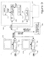
- the home network system comprises 2 boxes: a remote settop box 101 and a central settop box 102.
- the central settop box 102 includes a home network interface 103 and an IR packet decoder 104, although these functions could be separated into two physically distinct units.
- An IR cable 105 connects the IR packet decoder to an IR Blaster 106, whose construction may be conventional.
- a program source such as a VCR 107 is connected to network interface 103 by either an analog or digital link 108.
- An IR remote control 109 can now send IR commands 110 to remote settop box 101.
- Remote settop box 101 packetizes the IR commands 110 and forwards them across digital network 111 to network interface 103.
- IR packet decoder 104 translates packetized IR commands received from the network 111 and forwards them to IR blaster 106.
- IR blaster 106 broadcasts an IR blaster command 115 to conventional program source 107.
- the program source 107 responds to the commands and sends its program content to the digital network 111 via link 108 and the network interface 103.
- the remote display or speakers 112 receives the program from source 107, even though source 107 may be separated from IR remote 109 and display 112 by one or more walls 113.
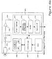
- FIG 4a is a detailed view of the remote settop box 101.
- the IR receiver 401 within the remote box is typically a photodiode, with a simple RC filter 402 at the output.
- the RC filter 402 is sufficiently broadband to receive all varieties of IR remote control signals.
- Most IR remote controls 109 generate signals 110 that are either baseband signals with pulse widths in the range of 3-7 ⁇ s on/20 ⁇ s off or AM modulated carriers around 30-40KHz.
- Buffer/amplifier 403 forwards the received signal to the remote signal processor 405 over interrupt line 404.
- the signal 110 is received, digitized, and packetized efficiently for distribution over the home network.
- the remote signal processor 405 in the remote settop box may perform this function in a number of ways:
- the pulse width modulated signal can be filtered by pulse width coding circuit 410 to remove any pulses less than 1 ⁇ s in width (this is the lower limit of pulse widths used in remote control signals).
- the filter removes the narrow pulse, and adds this time to the previous pulse width.
- the pulse width is measured with a high frequency clock, for example, 10Mhz or 100ns precision.
- the pulse width value is then coded as an 8 bit number, with some mechanism to encode very long periods of time with no change in level. This could be done by reserving the value 0 (0x00) to mean extend the pulse width count by 256. This very simple run-length coding could be improved with other simple data compression schemes.
- the bit rate on the network is usually very low, but could peak if there is a lot of IR noise in the system, or if the receiver is triggered by a high speed IR signal.
- the lower limit occurs if there is a slow IR signal, and is generally a single 8-bit number every 25.6 ⁇ s using a 10Mhz sample clock, resulting in 312Kbits/second. If there is no IR signal, the bandwidth is generally 0, as no information is sent.
- the upper limit occurs if there is a noisy signal received. Pulses just over 1 ⁇ s in length generally require an 8 bit number every 1 ⁇ s, or about 8Mbits/second.
- a peak data rate of 1 Mbit/second provides a reliable system that works with most commercially available remote controls.
- the advantages of this system is that it is independent of the protocol on the remote control, does not require a user to program the system, has some noise filtering and noise immunity, and requires no bandwidth when there is no IR signal received.
- the remote network interface The remote network interface.
- the remote network interface 412 in the remote settop box 101 is controlled by a software application running on control logic 407 to manage this process over the network. It implements a number of functions, for example:
- the remote settop box 101 on power-up, sends a message to the central settop box 102 to establish an IR connection. This could also be done when the user selects such a feature on the remote settop box. This essentially allows the remote settop box IR application software to pass information to the central box, which is also running an IR application software. Additionally, after the connection is made, the remote settop box or the central settop box sends brief messages every few minutes to ensure that the other box is still connected. Upon discovering a disconnect, the remote and central boxes attempt to re-establish a connection, with time-out and retry if the other box is still disconnected.
- the remote settop box may have it's own IR remote controller, and may process the commands from this controller.
- the control logic 407 examines the signal from the signal processor 405, determines if it matches the IR signal for the remote settop box control, and if so, does not transmit this on the network I/F 412. Instead it sends the resulting command to any local processor that may need to process commands for the remote box operation.
- This has at least two benefits: it allows the settop remote box to operate off the same IR receiver 401 as the network application, and also prevents re-transmission of the local IR signal, thus allowing multiple remote settop boxes on a network, while preventing other similar boxes from receiving these signals inadvertently through the network 111. In one embodiment, any remote settop box needs to respond only to its IR control.
- the remote settop box 101 and the IR controller for that box are programmed so that each remote control will only work with a single box, for example. All other signals are routed on the network for use by other boxes.
- the IR application software constructs a packet of information 430 to be used by the central settop box.
- a packet structure is shown in Figure 4b.
- This information starts with some header information, followed by a number of PWM samples 434.
- the header information 431 contains control bits to indicate the start of transmission (if the IR receiver was previously quiet) and end of transmission 432.
- the header indicates a packet length to allow the central box to know how much information is to be received.
- the header indicates a packet count or sequence number 433, which is simply an increment of +1 from the previous packet. Each packet in sequence has an increasing count. The count can be used by the central settop box to order the data, and allows simple buffering models (see below).
- the packets are a fixed, finite length of time. 50ms covers most IR transmitter times for a single control code word. Using the PWM approach above, a 50ms packet contains about 4000 bytes for typical IR codes with pulse periods of 25 ⁇ s or less if compression is used.
- the data that is transmitted is buffered prior to transmission, and buffered on receipt.
- Figure 4c shows one embodiment of how packets are "bundled" for network transmission. This ensures that the data is transmitted without gaps on the network.
- the network is typically packet based, and may have other information traffic. The resulting effect is that packets of IR information are not sent continuously.
- the buffer model can be very simple. For example, the system could buffer 4 packets on the transmit side, not start transmitting until 4 packets are available to send, and use 4 packets on the receiver side, while holding IR data at the central settop box until 4 packets are received.
- packets are generated every 50ms in the remote settop box 101 and consumed in the central settop box 102 every 50ms, so the system works as long as the data is sent within 4x50ms or about 200ms. As most IR remote controls 109 repeat the IR signal multiple times, the system is not sensitive to occasional network drop-outs.
- low delay operation ensures that the user does not perceive annoying delays from when they push a button on an IR remote until the operation starts to take effect. This may be achieved by two means. For example, first the data is sent to the network while the button is still being pressed. A typical key press may last a few seconds, and the signal processing and application software must not wait until the button press is complete to send data packets 430. Second, the buffer model for buffer 411 keeps a small number of packets of information in the buffer to ensure low delay from input (IR received at remote box) to output (IR blasted at central box). The buffer model above uses 8 packets of 50ms each for a 400ms total delay. This may be modified for different system performance goals.
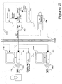
- Figure 2 shows a variation on the basic system embodiment shown in Figure 1.
- multiple remote settop boxes 101, 201 and program sources 107, 207 are connected to network 111.
- a stand-alone remote capture device 215 can be positioned at any convenient point on network 111 so that IR remotes 109, 209 can be used in any room, even rooms that contain no program sources 107, 207 or display or speaker devices 112, 212.
- Home digital network interface 202 is conventional and has digitizing ports for digitizing and forwarding digital audio 216 and video 217 across network 111.
- Figure 3 shows another embodiment of a system arrangement in accordance with the present invention.
- the functions of remote settop box 301 are built into display device 312, or may be as in Figure 1.
- Multiple display devices 312, 313 are connected to network 111.
- multiple clusters of program sources 340, 341 are also connected to the network.
- Central decode and distribute device 350 manages connections between the remote settop boxes and different media clusters, so that multiple remotes and sources can be accessed simultaneously.
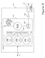
- the IR blaster 106 is typically an LED. In Figure 5 it is shown as part of the settop box, although it could be located remotely in a convenient transmitting location, high on a wall for example. Most IR remote controls are either baseband signals with pulse widths in the range of 3-7 ⁇ s on/20 ⁇ s off or AM modulated carriers around 30-40KHz.
- the packets are received from the network 111, depacketized, processed and driven to the IR blaster 106.
- the IR blaster 106 will transmit the signal into the room, where it will bounce off objects and reflect back into the A/V equipment 107 in the room.
- the central signal processor 501 in the central settop box is generally more complex than the remote settop box.
- Signal processor 501 is implemented on a microprocessor with the functions described below. It takes the packets of data 430 from the network 111, decodes the data according to the algorithm chosen, and using a time base similar to the remote settop box, reconstructs the original signal. An example would be using the PWM method described above, decompressing the values if entropy coding or Huffman coding was used to compress the signal in the remote settop box 101. After decompression, a 10Mhz clock 503 counts out the relevant clock cycles to recreate the pulse width of the signal, and the output of the pulse counter drives the LED either on or off via a driver 504 (full power) into the room.
- the central settop box also runs a software application that manages the system over the home network.
- the operations are, for example:
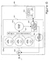
- FIG. 6 shows a "central decode and universal translate" device that can be used with the system shown in Figure 3, for example.
- This device may have all of the functions of the central signal processor 501, except instead of converting packets into IR signals, the converted packets are examined for header information that identifies the appropriate program source and remote for each packet.
- This device can be connected to network 111 at any convenient point through network interface 602. The packets are then routed to the appropriate media source cluster 340. This is possible since the central decoder 350 is made "aware" of which remotes are associated with each source via user input from interface 606.
- a look-up table 650 correlates each remote 109 with each source 107 or media cluster 340. Each packet is then appropriately addressed by re-packetizer 660 and sent back across the network 111.
- this central universal translate the "any to any" IR control shown in Fig. 7 can be accomplished.
- Embodiments of the present invention are quite different than known systems that utilize convention radio retransmission of IR signals. Notably, the system described here has at least the following advantages:
Landscapes
- Engineering & Computer Science (AREA)
- Signal Processing (AREA)
- Multimedia (AREA)
- Automation & Control Theory (AREA)
- Computer Networks & Wireless Communication (AREA)
- Human Computer Interaction (AREA)
- Selective Calling Equipment (AREA)
- Small-Scale Networks (AREA)
Claims (12)
- Système servant à contrôler des sources multimédia (107) par l'intermédiaire d'un réseau (111), comprenant :a) un premier dispositif d'interface (101) raccordé au réseau (111) opérationnellement et situé avec un dispositif (112) servant à réviser du média provenant d'une source multimédia (107) ; ledit premier dispositif d'interface (101) comprenant un boîtier décodeur distant ;b) un second dispositif d'interface (102) raccordé au réseau (111) opérationnellement et étant situé avec ladite source multimédia (107) ; ledit second dispositif d'interface (102) comprenant un boîtier décodeur central comportant une interface réseau domestique (103) ;c) ledit premier dispositif d'interface (101) destiné à convertir une commande d'une commande à distance (109) vers un format compatible avec ledit réseau (111) et à transférer la commande convertie à ladite interface réseau domestique (103) ;d) ladite source multimédia (107) destiné à être raccordée via une liaison (108) à ladite interface réseau domestique (103) ;e) ledit second dispositif d'interface (102) destiné à traduire la commande convertie et à transférer la commande traduite à un programmeur de transmission à infrarouges (106) qui diffuse la commande traduite à ladite source multimédia (107) ; et
caractérisé en ce quef) ladite source multimédia (107) est adaptée pour envoyer ledit média audit réseau (111) via ladite liaison (108) et ladite interface réseau domestique (103) en réponse à la commande traduite. - Système selon la revendication 1 dans lequel le premier dispositif d'interface (101) comprend un processeur de signal qui génère des paquets de données représentant les commandes de la commande à distance (109) et communique lesdits paquets de données sur le réseau (111).
- Système selon la revendication 2 dans lequel le processeur de signal est programmé pour amener lesdits paquets de données à être mis en mémoire tampon avant de communiquer lesdits paquets de données sur le réseau (111).
- Système selon la revendication 1 dans lequel le premier dispositif d'interface (101) comprend en outre une interface utilisateur qui reçoit au moins une commande de la commande à distance (109) indiquant un type de commande à distance (109) qui est utilisé, et dans lequel le premier dispositif d'interface (101) génère le format compatible avec ledit réseau basé sur le type de commande à distance (109) utilisé.
- Système selon la revendication 4 dans lequel le premier dispositif d'interface (101) comprend en outre de la mémoire, et dans lequel le type de commande à distance (109) qui est utilisé est déterminé par une comparaison de la au moins une commande à une information stockée dans la mémoire.
- Système selon la revendication 1 dans lequel le premier dispositif d'interface (101) comprend en outre un récepteur sans fil qui reçoit les commandes de la commande à distance (109), dans lequel le premier dispositif d'interface génère le format compatible avec ledit réseau en échantillonnant le récepteur sans fil, et dans lequel le premier dispositif d'interface communique les échantillons générés sur le réseau (111).
- Système selon la revendication 1 dans lequel le premier dispositif d'interface génère le format compatible avec ledit réseau en utilisant un procédé de modulation d'impulsions en durée.
- Système selon la revendication 7 dans lequel le procédé de modulation d'impulsions en durée comprend la génération d'une valeur d'impulsions en durée utilisant les commandes de la commande à distance (109) et le codage de la valeur d'impulsions en durée.
- Système selon la revendication 1 dans lequel le second dispositif d'interface comprend un processeur de signal qui reçoit et décode des paquets de données représentant les commandes de la commande à distance (109), et reconstruit un signal original à partir des données décodées.
- Système selon la revendication 9 comprenant en outre un transmetteur sans fil servant à diffuser le signal original.
- Système selon la revendication 1 dans lequel ledit boîtier décodeur central comprend des moyens destinés à pinguer le réseau (111) afin de trouver les boîtiers décodeurs distants qui ont été mis sous tension.
- Système selon la revendication 1 dans lequel ledit boîtier décodeur central comprend des moyens destinés à individualiser la communication avec les boîtiers décodeurs distants afin d'attribuer différents boîtiers décodeurs distants pour utiliser différentes sources multimédia (107).
Priority Applications (1)
| Application Number | Priority Date | Filing Date | Title |
|---|---|---|---|
| DE2003617004 DE60317004T2 (de) | 2003-04-08 | 2003-04-08 | System und Methode zur Unterstützung einer Infrarot-Fernbedienung über ein Netz |
Applications Claiming Priority (2)
| Application Number | Priority Date | Filing Date | Title |
|---|---|---|---|
| US10/116,217 US20030195969A1 (en) | 2002-04-04 | 2002-04-04 | System and method supporting infrared remote control over a network |
| US116217 | 2002-04-14 |
Publications (2)
| Publication Number | Publication Date |
|---|---|
| EP1353475A1 EP1353475A1 (fr) | 2003-10-15 |
| EP1353475B1 true EP1353475B1 (fr) | 2007-10-24 |
Family
ID=28453931
Family Applications (1)
| Application Number | Title | Priority Date | Filing Date |
|---|---|---|---|
| EP03008158A Expired - Lifetime EP1353475B1 (fr) | 2002-04-04 | 2003-04-08 | Système et procède supportant la telecommande à infrarouge sur un reseau |
Country Status (2)
| Country | Link |
|---|---|
| US (2) | US20030195969A1 (fr) |
| EP (1) | EP1353475B1 (fr) |
Families Citing this family (36)
| Publication number | Priority date | Publication date | Assignee | Title |
|---|---|---|---|---|
| US20040010560A1 (en) * | 2002-07-10 | 2004-01-15 | Sandage David A. | Method and apparatus to transmit infrared signals generated from a computer application using a remote device |
| US6998955B2 (en) * | 2002-08-09 | 2006-02-14 | Ballew Michael A | Virtual electronic remote control device |
| JP2004228647A (ja) * | 2003-01-20 | 2004-08-12 | Toshiba Corp | 電子機器およびリモートコントローラ |
| US20040157548A1 (en) * | 2003-02-06 | 2004-08-12 | Eyer Mark Kenneth | Home network interface legacy device adapter |
| US20040203387A1 (en) * | 2003-03-31 | 2004-10-14 | Sbc Knowledge Ventures, L.P. | System and method for controlling appliances with a wireless data enabled remote control |
| US20050102652A1 (en) * | 2003-11-07 | 2005-05-12 | Sony Corporation | System and method for building software suite |
| US20050135628A1 (en) * | 2003-11-17 | 2005-06-23 | Sony Corporation | System and method for authenticating components in wireless home entertainment system |
| CN1333539C (zh) * | 2003-12-29 | 2007-08-22 | 明基电通股份有限公司 | 远程遥控电子装置的方法 |
| US7734831B2 (en) * | 2004-07-02 | 2010-06-08 | Hewlett-Packard Development Company, L.P. | Universal remote control device for controlling entertainment-related functions |
| US7418528B2 (en) * | 2004-07-22 | 2008-08-26 | Texas Instruments Incorporated | Multimode, multiline data transfer system and method of operating the same |
| JP4207900B2 (ja) * | 2004-12-22 | 2009-01-14 | ソニー株式会社 | リモコン・システム、リモート・コマンダ、並びにリモコン・サーバ |
| GB0525547D0 (en) * | 2005-12-15 | 2006-01-25 | Symfony Technology Ltd | An electronic home entertainment device |
| US7640577B2 (en) * | 2006-02-14 | 2009-12-29 | Sony Corporation | System and method for authenticating components in wireless home entertainment system |
| TWI328936B (en) * | 2006-09-01 | 2010-08-11 | Live Experiment Design Corp | Remote controlling system for controlling electronic equipments within situation |
| JP4270270B2 (ja) * | 2006-12-05 | 2009-05-27 | ソニー株式会社 | 電子機器、撮像装置、電子機器の制御方法およびプログラム |
| KR101532369B1 (ko) * | 2006-12-11 | 2015-06-29 | 삼성전자주식회사 | 휴대용 단말기의 원격제어 장치 및 방법 |
| WO2008078220A2 (fr) * | 2006-12-20 | 2008-07-03 | Grundig Elektronik Anonim Sirketi | Procédé de distribution de commandes de contrôle à distance |
| DE102007015788B3 (de) * | 2007-03-30 | 2008-10-23 | Fm Marketing Gmbh | Multimedia-Einrichtung und Verfahren zur Datenübertragung bei einer Multimedia-Einrichtung |
| EP2001223B1 (fr) | 2007-06-04 | 2016-09-21 | fm marketing gmbh | Agencement multimédia |
| CA2712354A1 (fr) * | 2008-01-29 | 2009-08-06 | Thomson Licensing | Procede, appareil et systeme de redirection de codes de commande infrarouge via un reseau, pour la commande et le traitement |
| US20100095342A1 (en) * | 2008-08-06 | 2010-04-15 | Belkin International, Inc. | Wireless content transmission and control |
| DE102008050988A1 (de) * | 2008-09-01 | 2010-03-04 | Gerd Reime | Identifikationselement mit einem optischen Transponder |
| JP2010109446A (ja) * | 2008-10-28 | 2010-05-13 | Sony Corp | 制御装置、電子機器の制御システム、および電子機器の制御方法 |
| US9142120B2 (en) | 2008-12-23 | 2015-09-22 | At&T Intellectual Property I, L.P. | Remote control device signal distribution |
| GB2480737A (en) * | 2009-03-24 | 2011-11-30 | Logitech Europ Sa | Apparatus and method of operation for a remote control system |
| FR2944169B1 (fr) * | 2009-04-03 | 2012-06-08 | Metronic | Procede et dispositif de deport de telecommande infrarouge numerique universel et systeme de transmission audio/video associe. |
| US20100258729A1 (en) * | 2009-04-13 | 2010-10-14 | Niles Audio Corporation | Infrared Repeater System |
| US8395477B2 (en) * | 2009-10-29 | 2013-03-12 | Time Warner Cable Inc. | Geographic based remote control |
| TW201124906A (en) * | 2010-01-14 | 2011-07-16 | Amtran Technology Co Ltd | Interactive system |
| JP5459262B2 (ja) * | 2011-05-20 | 2014-04-02 | ヤマハ株式会社 | スピーカ装置 |
| CN104902313B (zh) * | 2015-05-28 | 2018-12-18 | 成都市斯达鑫辉视讯科技有限公司 | 一种方便视频切换的机顶盒遥控器 |
| US10225377B2 (en) * | 2016-07-29 | 2019-03-05 | Microsoft Technology Licensing, Llc | Protocol translation with delay |
| US9866904B1 (en) | 2016-11-10 | 2018-01-09 | Roku, Inc. | Interaction recognition of a television content interaction device |
| CN107067702A (zh) * | 2017-03-17 | 2017-08-18 | 安科智慧城市技术(中国)有限公司 | 排爆系统 |
| US11064573B2 (en) * | 2017-07-24 | 2021-07-13 | Haier Us Appliance Solutions, Inc. | Determining resonant frequency for quasi-resonant induction cooking devices |
| EP4109911A4 (fr) * | 2020-02-21 | 2023-11-22 | LG Electronics, Inc. | Dispositif et procédé d'affichage |
Citations (2)
| Publication number | Priority date | Publication date | Assignee | Title |
|---|---|---|---|---|
| DE4123206A1 (de) * | 1991-07-10 | 1993-01-14 | Schwab Technologieberatung | System zur uebertragung von fernsteuerbefehlen ueber ein leitungsnetz |
| WO1999057698A1 (fr) * | 1998-05-04 | 1999-11-11 | Conexant Systems, Inc. | Systeme et procede d'extension de la portee d'une unite de base |
Family Cites Families (23)
| Publication number | Priority date | Publication date | Assignee | Title |
|---|---|---|---|---|
| US4882747A (en) * | 1988-05-12 | 1989-11-21 | Jerry Williams | Infrared communication apparatus for remote site applications |
| GB2219164A (en) * | 1988-05-24 | 1989-11-29 | Michael Peacock | Infra red consolidator and repeater |
| US4866434A (en) * | 1988-12-22 | 1989-09-12 | Thomson Consumer Electronics, Inc. | Multi-brand universal remote control |
| US5247347A (en) * | 1991-09-27 | 1993-09-21 | Bell Atlantic Network Services, Inc. | Pstn architecture for video-on-demand services |
| US5404393A (en) * | 1991-10-03 | 1995-04-04 | Viscorp | Method and apparatus for interactive television through use of menu windows |
| US5539449A (en) * | 1993-05-03 | 1996-07-23 | At&T Corp. | Integrated television services system |
| US5386251A (en) * | 1993-06-03 | 1995-01-31 | Zilog, Inc. | Television receiver with learning remote control system capable of being controlled by a remote control device manufactured by different companies |
| US5675375A (en) * | 1994-12-15 | 1997-10-07 | Harris Corporation | Home videoconferencing system (HVS) |
| DE19530727B4 (de) * | 1995-08-18 | 2012-09-20 | Kiekert Ag | Verfahren zum Betrieb eines Steuersystems zur Steuerung von Kraftfahrzeugkomponenten |
| US6005861A (en) * | 1995-11-22 | 1999-12-21 | Samsung Electronics Co., Ltd. | Home multimedia network architecture |
| JPH09238205A (ja) * | 1996-02-29 | 1997-09-09 | Toshiba Corp | スピーカホン装置の構成方法及び情報処理装置 |
| US6097520A (en) * | 1997-06-30 | 2000-08-01 | Microsoft Corporation | Remote control receiver and method of operation |
| US6026150A (en) * | 1997-10-30 | 2000-02-15 | Epigram | Network protocol--based home entertainment network |
| US6275167B1 (en) * | 1998-06-08 | 2001-08-14 | Visteon Global Technologies, Inc. | Method and system for communicating between remote-controlled modules in automotive vehicles |
| US6157319A (en) * | 1998-07-23 | 2000-12-05 | Universal Electronics Inc. | Universal remote control system with device activated setup |
| US6111677A (en) * | 1998-08-31 | 2000-08-29 | Sony Corporation | Optical remote control interface system and method |
| US6137539A (en) * | 1998-10-09 | 2000-10-24 | Matshushita Electric Industrial Co, Ltd | Digital television status display |
| US6796555B1 (en) * | 1999-07-19 | 2004-09-28 | Lucent Technologies Inc. | Centralized video controller for controlling distribution of video signals |
| JP4660877B2 (ja) * | 2000-01-11 | 2011-03-30 | ソニー株式会社 | 電子機器システム |
| AU2002234258A1 (en) * | 2001-01-22 | 2002-07-30 | Sun Microsystems, Inc. | Peer-to-peer network computing platform |
| US7346917B2 (en) * | 2001-05-21 | 2008-03-18 | Cyberview Technology, Inc. | Trusted transactional set-top box |
| US7617515B1 (en) * | 2001-05-24 | 2009-11-10 | Vixs Systems, Inc. | Method and apparatus for managing resources in a multimedia system |
| US7574723B2 (en) * | 2001-07-19 | 2009-08-11 | Macrovision Corporation | Home media network |
-
2002
- 2002-04-04 US US10/116,217 patent/US20030195969A1/en not_active Abandoned
-
2003
- 2003-04-08 EP EP03008158A patent/EP1353475B1/fr not_active Expired - Lifetime
-
2013
- 2013-08-30 US US14/014,729 patent/US9338496B2/en not_active Expired - Fee Related
Patent Citations (2)
| Publication number | Priority date | Publication date | Assignee | Title |
|---|---|---|---|---|
| DE4123206A1 (de) * | 1991-07-10 | 1993-01-14 | Schwab Technologieberatung | System zur uebertragung von fernsteuerbefehlen ueber ein leitungsnetz |
| WO1999057698A1 (fr) * | 1998-05-04 | 1999-11-11 | Conexant Systems, Inc. | Systeme et procede d'extension de la portee d'une unite de base |
Also Published As
| Publication number | Publication date |
|---|---|
| US20140233909A1 (en) | 2014-08-21 |
| US20030195969A1 (en) | 2003-10-16 |
| US9338496B2 (en) | 2016-05-10 |
| EP1353475A1 (fr) | 2003-10-15 |
Similar Documents
| Publication | Publication Date | Title |
|---|---|---|
| EP1353475B1 (fr) | Système et procède supportant la telecommande à infrarouge sur un reseau | |
| CA2303920C (fr) | Reseau de divertissement domestique a base d'un protocole de reseau | |
| US9942604B2 (en) | Legacy converter | |
| US7653091B2 (en) | Apparatus for synchronization of digital multimedia data communicated over wired media | |
| AU2008207498B2 (en) | Network speaker for an audio network distribution system | |
| US7194755B1 (en) | Information signal transmission system and remote control device for the same | |
| CN101039527B (zh) | 遥控信号传输系统 | |
| US20050235329A1 (en) | Systems and methods for integrated control within a home entertainment system | |
| US20030018975A1 (en) | Method and system for wireless audio and video monitoring | |
| JP2001509929A (ja) | 遠隔制御システム用通信システム | |
| CA2448556A1 (fr) | Systeme infrarouge a point de connexion | |
| CN1133321C (zh) | 用于通信接收机的双向外部设备接口 | |
| JP2506969B2 (ja) | リモコン操作型送信機能付電子機器 | |
| US20040155809A1 (en) | Infrared remote control command network pass-through | |
| CN1381958A (zh) | 在音频和/或视频装置间双向通信的无线互连方法和设备 | |
| JP2003219486A (ja) | 映像音声受信装置、被制御装置、及び遠隔制御システム | |
| DE60317004T2 (de) | System und Methode zur Unterstützung einer Infrarot-Fernbedienung über ein Netz | |
| AU2011211407A1 (en) | Audio video distribution system using multiple network speaker nodes in a multi speaker session | |
| WO2006050640A1 (fr) | Dispositif de transmission reseaute comprenant une commande infrarouge a distance et dote d'une fonction de transmission de signaux audio/video | |
| JP2004015355A (ja) | リモートコントローラコード送信装置、およびリモートコントローラコード受信装置 | |
| KR100430483B1 (ko) | 전력선 통신을 이용한 리모콘의 적외선 신호 전송장치 | |
| JP2006157370A (ja) | ネットワーク型映像制御装置およびその制御方法 | |
| KR101116377B1 (ko) | 이동단말의 조작 반응성을 개선할 수 있는 방송지원장치와, 조작 반응성이 개선된 이동단말 | |
| WO2007005114A1 (fr) | Dispositif permettant de synchroniser des donnees multimedia numeriques transmises par des supports cables | |
| JPH0573993A (ja) | Vtr制御装置 |
Legal Events
| Date | Code | Title | Description |
|---|---|---|---|
| PUAI | Public reference made under article 153(3) epc to a published international application that has entered the european phase |
Free format text: ORIGINAL CODE: 0009012 |
|
| AK | Designated contracting states |
Kind code of ref document: A1 Designated state(s): AT BE BG CH CY CZ DE DK EE ES FI FR GB GR HU IE IT LI LU MC NL PT RO SE SI SK TR |
|
| AX | Request for extension of the european patent |
Extension state: AL LT LV MK |
|
| 17P | Request for examination filed |
Effective date: 20040415 |
|
| AKX | Designation fees paid |
Designated state(s): DE FR GB |
|
| 17Q | First examination report despatched |
Effective date: 20040709 |
|
| GRAP | Despatch of communication of intention to grant a patent |
Free format text: ORIGINAL CODE: EPIDOSNIGR1 |
|
| GRAS | Grant fee paid |
Free format text: ORIGINAL CODE: EPIDOSNIGR3 |
|
| RAP1 | Party data changed (applicant data changed or rights of an application transferred) |
Owner name: BROADCOM CORPORATION |
|
| GRAA | (expected) grant |
Free format text: ORIGINAL CODE: 0009210 |
|
| AK | Designated contracting states |
Kind code of ref document: B1 Designated state(s): DE FR GB |
|
| REG | Reference to a national code |
Ref country code: GB Ref legal event code: FG4D |
|
| REF | Corresponds to: |
Ref document number: 60317004 Country of ref document: DE Date of ref document: 20071206 Kind code of ref document: P |
|
| ET | Fr: translation filed | ||
| PLBE | No opposition filed within time limit |
Free format text: ORIGINAL CODE: 0009261 |
|
| STAA | Information on the status of an ep patent application or granted ep patent |
Free format text: STATUS: NO OPPOSITION FILED WITHIN TIME LIMIT |
|
| 26N | No opposition filed |
Effective date: 20080725 |
|
| PGFP | Annual fee paid to national office [announced via postgrant information from national office to epo] |
Ref country code: GB Payment date: 20130422 Year of fee payment: 11 |
|
| PGFP | Annual fee paid to national office [announced via postgrant information from national office to epo] |
Ref country code: FR Payment date: 20130523 Year of fee payment: 11 |
|
| PGFP | Annual fee paid to national office [announced via postgrant information from national office to epo] |
Ref country code: DE Payment date: 20140430 Year of fee payment: 12 |
|
| REG | Reference to a national code |
Ref country code: DE Ref legal event code: R119 Ref document number: 60317004 Country of ref document: DE |
|
| GBPC | Gb: european patent ceased through non-payment of renewal fee |
Effective date: 20140408 |
|
| REG | Reference to a national code |
Ref country code: DE Ref legal event code: R119 Ref document number: 60317004 Country of ref document: DE Effective date: 20141101 |
|
| REG | Reference to a national code |
Ref country code: FR Ref legal event code: ST Effective date: 20141231 |
|
| PG25 | Lapsed in a contracting state [announced via postgrant information from national office to epo] |
Ref country code: GB Free format text: LAPSE BECAUSE OF NON-PAYMENT OF DUE FEES Effective date: 20140408 Ref country code: DE Free format text: LAPSE BECAUSE OF NON-PAYMENT OF DUE FEES Effective date: 20141101 |
|
| PG25 | Lapsed in a contracting state [announced via postgrant information from national office to epo] |
Ref country code: FR Free format text: LAPSE BECAUSE OF NON-PAYMENT OF DUE FEES Effective date: 20140430 |