EP1354657A2 - Lötpatronenkörper mit ersetzbaren Lötspitzen und Lötkolben zur Verwendung hiermit - Google Patents
Lötpatronenkörper mit ersetzbaren Lötspitzen und Lötkolben zur Verwendung hiermit Download PDFInfo
- Publication number
- EP1354657A2 EP1354657A2 EP03006580A EP03006580A EP1354657A2 EP 1354657 A2 EP1354657 A2 EP 1354657A2 EP 03006580 A EP03006580 A EP 03006580A EP 03006580 A EP03006580 A EP 03006580A EP 1354657 A2 EP1354657 A2 EP 1354657A2
- Authority
- EP
- European Patent Office
- Prior art keywords
- tip
- soldering
- end part
- heater
- cartridge
- Prior art date
- Legal status (The legal status is an assumption and is not a legal conclusion. Google has not performed a legal analysis and makes no representation as to the accuracy of the status listed.)
- Withdrawn
Links
Images

Classifications
-
- B—PERFORMING OPERATIONS; TRANSPORTING
- B23—MACHINE TOOLS; METAL-WORKING NOT OTHERWISE PROVIDED FOR
- B23K—SOLDERING OR UNSOLDERING; WELDING; CLADDING OR PLATING BY SOLDERING OR WELDING; CUTTING BY APPLYING HEAT LOCALLY, e.g. FLAME CUTTING; WORKING BY LASER BEAM
- B23K3/00—Tools, devices or special appurtenances for soldering, e.g. brazing, or unsoldering, not specially adapted for particular methods
- B23K3/02—Soldering irons; Bits
- B23K3/03—Soldering irons; Bits electrically heated
- B23K3/0338—Constructional features of electric soldering irons
- B23K3/0369—Couplings between the heating element housing and the bit or tip
-
- B—PERFORMING OPERATIONS; TRANSPORTING
- B23—MACHINE TOOLS; METAL-WORKING NOT OTHERWISE PROVIDED FOR
- B23K—SOLDERING OR UNSOLDERING; WELDING; CLADDING OR PLATING BY SOLDERING OR WELDING; CUTTING BY APPLYING HEAT LOCALLY, e.g. FLAME CUTTING; WORKING BY LASER BEAM
- B23K3/00—Tools, devices or special appurtenances for soldering, e.g. brazing, or unsoldering, not specially adapted for particular methods
- B23K3/02—Soldering irons; Bits
- B23K3/03—Soldering irons; Bits electrically heated
- B23K3/0315—Quick-heating soldering irons having the tip-material forming part of the electric circuit
Definitions
- This invention relates generally to soldering irons and soldering stations used in modern electronic production, rework and repair applications which are temperature controlled, and specifically relates more to production type soldering stations which feature a heater which is either replaceable or integral with the soldering handpiece and which utilizes separately replaceable tips which wear during normal use.
- the invention also relates to such soldering irons and soldering stations which use a combined tip/heater cartridge, and in which the entire tip/heater cartridge is changed when the tip wears out.
- the products the first type mentioned above are produced by WELLER®, PACE®, ANTEX®, ERSA® and HAKKO® ; see also, commonly owned, co-pending U.S. Patent Application 09/973,952.
- the products of the second type mentioned above include the tip/heater cartridge product of METCAL INCORPORATED, or a combined heater/thermocouple arrangement such as that found in U.S. Patent No. 5,043,560 (Masreliez) and in the Model 941 soldering station of the Hakko Corporation (Miyazaki U.S. Patent No. 6,054,678); see also, U.S. Patent 4,839,501 of METCAL® and commonly owned, co-pending U.S. Patent Applications 09/972,194 and 10/046,545.
- tip/heater cartridge stations Compared with traditional soldering stations, tip/heater cartridge stations generally offer significantly improved heat delivery and responsiveness as well as a slim, lightweight and often cooler handpiece which many operators prefer.
- soldering stations for modern, high-reliability electronic production, rework and repair applications (hereinafter, "soldering stations” shall also include “soldering irons”) have become the generally accepted norm due to their ability to maintain a safe, appropriate, user-selected tip operating temperature for the particular application at hand.
- Such traditional soldering stations generally feature a soldering iron handpiece which consists of a handle and a closed-loop temperature controlled heater onto which a replaceable soldering tip is attached through various means, examples of which include the products made by WELLER®, PACE®, ANTEX®, ERSA® and HAKKO®.
- These tip attachment means include a variety of configurations which are well known to the art.
- One configuration is a hollow heater into which tips are installed and fastened with set screws.
- Another configuration includes a thin cylindrical heater over which a hollow tip is installed and held in place by a shroud which fits over a shoulder on the tip and is fastened to the handpiece with a nut.
- Still another tip attachment means includes a thin, cylindrical heater with a stainless steel shroud over which a hollow tip is installed and held fast by some spring means which includes a separate spring ring, a spit in the open end of the tip that fits over the shroud, a combination of these two features or an independent coil spring with one end attached to the handpiece and the other end formed in a small hook shape which when stretched slightly engages a hole in the side of the tip thereby holding it in place.
- tip/heater cartridge stations With their attendant advantages outlined above have become quite popular, particularly in the large contract manufacturing environments.
- tip life either conventional tips or tip/heater cartridges
- tip operating temperature is limited by several factors, such as tip operating temperature, iron plating thickness, solder flux composition and other factors, these tips must be replaced quite frequently, sometimes as often as once per day depending on usage.
- soldering tips are relatively inexpensive as discussed above, replacing of tip/heater cartridges can be quite expensive as these cost anywhere from upwards of $12 to $24 dollars each or more.
- a further object of the present invention is to provide an easily replaceable, inexpensive heater cartridge and tip combination which offers improved physical dimensions (such as a short tip-to grip for better control, and a thin heater and tip for easy access and viewing in tight spaces) in addition to improved heat transfer and responsiveness relative to conventional soldering irons.
- a heater cartridge composed of a stainless steel tube, a ceramic-potted heater assembly contained within a cylinder closed at one end which is either squared off or tapered and made from a high thermal conductivity material, such as silver, and wherein the heating element is connected to a dissimilar metal which forms a thermocouple, also containing cold lead wires of greater cross-sectional area than the heating element, an end insert which supports and fixes electrical contacts, and wire insulation.
- the heater cartridge accommodates a replaceable tip which slips over the closed end and is retained, e.g., by a spring, clip, internal thread mating to an external thread on the heater, a pin on the heater and track on the tip, interference fit between tip and heater, or other means.
- the heater cartridge with slip-on tip offers an economic advantage to its users.
- the user can have several heater cartridges and slip-on tips so that when a new or alternate tip is required, the heater cartridge with slip-on tip is removed and a cool heater cartridge (with a replacement slip-on tip already attached) is installed into to the iron.
- the user need not inventory a large number of tip heater cartridges, but instead needs only a few heater cartridges at each station.
- Inexpensive slip-on tips can be inventoried at substantially lower cost and require less storage space than their costly tip heater cartridge counterparts.
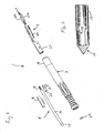
- Fig. 1 is an exploded view of a preferred embodiment soldering iron with a heater cartridge in accordance with the present invention with the soldering tip removed;
- Fig. 2 is a cross-sectional view of the front end portion of the Fig. 1 heater cartridge
- Fig. 3 is a side view of a soldering tip for used with the Fig. 1 heater cartridge
- Fig. 4 is a plan view of a spring clip for use with the Fig. 3 soldering tip
- Figs. 5-7 each show a respective alternative arrangement for mounting and retaining of a soldering tip on the end of a heater cartridge
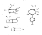
- Fig. 8 is a side view of another alternative solder tip arrangement for mounting and retaining of a soldering tip on the end of a heater cartridge;
- Fig. 9 a cross-section taken along line 9-9 in Fig. 8 with an illustration of a spring clip being slid thereon;
- Fig. 10 is a side view of the front end portion of an alternative heater cartridge.
- Fig 11 shows the Fig. 8 soldering tip mounted on the Fig 10 heater cartridge using a spring clamp.
- the soldering iron 1 in accordance with the present invention has a handpiece 3 and a heater cartridge 4.
- the handpiece 3 has an elongated hollow body with an inner passage that is open at an outer end of the passage for receiving the heater cartridge 4.
- An electrical connector assembly 7 is mounted in an inner end of the passage, being inserted from the opposite direction as the cartridge 4, and then being held in place by an end cap 9 that is screwed onto threads (not shown) of the handpiece 3 and through which an electric power cord (not shown) extends. This constructional feature allows the connector assembly 7 to be removed for maintenance or repair.
- the electrical connector assembly 7 may comprise leaf spring connectors 21a, 21b, 21c, which are mounted in a receptacle body 23 which has slots for reception thereof.
- the leaf spring connectors 21a, 21b slide onto the plate-shaped electrical connectors 18 to form an electrical connection with an electrical heater 12 (Fig. 2) located in a tip end part 14 that is mounted at the front end of the tubular body member 10 of the cartridge 4.
- the leaf spring connector 21c slides onto the tubular body member 10 (which is preferably made of stainless steel) of cartridge 4 to provide a grounding interface connection therewith, as the inner end of the heater cartridge 4 is moved into the tubular portion of the receptacle body 23.
- a bent tab of one of the plate-shaped electrical connectors 18 is shown attached to an end of one of the leads of the cartridge heater in Fig. 2, it should be appreciated that this connection is formed after the leads are passed through a cartridge end cap 22 which has surfaces and notches for receiving and supporting plate-shaped connectors 18 and their bent tabs.
- An O-ring 27 is mounted at the front end of the receptacle body 23 and is held thereagainst by a formation on an inner surface of the handpiece 3.
- the O-ring 27 forms a sealed interface with respect to the tubular body member 10 of the heater cartridge 4 when it is fully inserted.
- the O-ring also serves to assist in retaining the cartridge within the handle and provides additional lateral support to the cartridge 4.
- a sleeve 16 is mounted on the exterior of the cartridge 10 body for orienting and supporting the cartridge 4 relative to the soldering iron handpiece 3 by engagement thereof with inner surface areas of said passage.
- the tip end part 14 constitutes the soldering tip in the soldering irons of the prior art, such is not the case in accordance with the present invention.
- the tip end part 14 in accordance with the present invention is designed to give the heater cartridge a replaceable tip capacity.
- the tip end part 14 is formed of a material of high thermal conductivity in comparison to a material of which the stainless steel tubular body member 10 of the cartridge body is formed, the material of high thermal conductivity preferably is silver, but the material of high thermal conductivity can be copper or other materials of comparable thermal conductivity.
- the tip end part 14 is preferably a separate element fixedly joined to the tubular body member 10 of the cartridge body 4, it can be formed as an integral part thereof.
- the soldering tip 20 has an expandable open end portion 20a for mounting over the tip end part 14.
- the expandability of the open end portion 20a of the soldering tip 20 is produced by a plurality axial slots 21 formed in the peripheral wall 20b of the open end portion 20a, only one of which is shown.
- a securing member in the form of a C-shaped ring clamp 22 (Fig. 4) is seatable on the expandable end portion 20a for restraining expansion thereof, thereby releasably holding the soldering tip 20 on the tip end part 14.
- the peripheral wall 20b has a circumferentially extending seating recess 20c formed therein for holding the C-shaped ring clamp 22.
- a snap-ring spring clamp or other securement means could be used instead of the C-shaped ring clamp 22.
- a separate securing means can be omitted, e.g., if the "legs" formed by the slits 21 are shaped to be placed under a radial pre-stress when mounted on the cartridge 4 by being outwardly deflected in such a mounted state.
- clamp 22 can have flat, band-shaped cross section. In such a case, the seating recess 20c can be omitted. Additionally, because of its proximity to the heater, the claim 22 is preferably made of a high temperature resistant material, such as Inconel®.
- the peripheral wall of the tip end part 14 has the same outer diameter as the outer diameter of the tubular body member 10, except where it is reduced for insertion into the tubular body member 10.
- the soldering tip 20 has a cylindrical receiving chamber 20d with a conic bottom wall, and the tip end part has a cylindrical peripheral wall and conic end face matched to the size and shape of the receiving chamber for providing a removable slip-on fit with optimized heat transfer communication between the soldering tip and tip end part.
- soldering tip 20 has an inner diameter in the embodiments of Figs. 5 & 6, the peripheral wall of the soldering tip 20', 20" have substantially the same outer diameter as the outer diameter of the tubular body member 10 and seat on a portion of a tip end part 14', 14" that has an outer diameter that is reduced relative to outer diameter of the tubular body member 10 by the thickness of the peripheral wall surrounding the receiving chamber.
- a ring 25 is mounted in an annular seat recess of the peripheral wall of the receiving chamber.
- the ring 25 has an inner diameter that is smaller than the outer diameter of portion of the tip end part 14' on which mounts so that, insertion of the tip end part 14' into the receiving chamber stretches the ring, which can be a C-shaped ring clamp similar to clamp 22 or an annular coil spring or the like, radially outwardly to an extent creating sufficient spring force to hold the tip in place, but still allowing removal of the tip 20'.
- a compressible ring, detent member 28 is located in an annular seat recess 14"a surrounding the reduced diameter portion of the tip end part 10" on which tip 20" is mounted.
- the soldering tip 20" has an annular seating groove 20"c which communicates with a pair of radial tool holes 20"e that are located 180° apart. As the soldering tip 20" is slid onto the tip end part, the ring detent member 28 is compressed into the seat recess 14"a.
- the seating groove 20"c is axially aligned with the recess 14"a and the ring detent member 28 expands radially outward into the seating groove 20"c, holding the soldering tip 20" in place.
- ends of a forceps-like tool T is inserted into the tool holes 20"e and is used to compress the ring detent member 28 sufficiently to become disengaged from the seating groove and to pull the soldering tip 20" forward.
- soldering tip 20''' has the female slot part 29 of a bayonet type lock and the tip end part carries the male pin part 20 of the bayonet type lock.
- Figs. 8 & 9 show a soldering tip 20'''' that is designed for use with either a hose type clamp or a spring clip.
- open end 20''''a has a noncircular transverse cross-sectional shape as is shown in Fig. 9.
- a pair of lobes 35 are formed 180° apart and have slots 35a formed therein.
- a spring clip 40 can be slid in the direction of the arrow in Fig. 9, through slots 35 onto tip end part so as to hold the tip 20'''' in place.
- a hose type clamp can be expanded and slid axially over the tip and then released to engage tip end part via the slots 35; see, Fig. 11.
- the tip end part 14'''' can have a rounded end instead of the drill point shape shown in Figs. 1 & 2, which is particularly useful when the tip end part is formed of a silver casting or a sintered silver body.
- tip end part 14'''' can have a maximum outer diameter that is smaller than an outer diameter of said tubular body member and can be force-fit mounted in an open end of the body member 10.
- the receiving chamber 20''''d of the soldering tip is given a rounded shape matched to it.
- soldering tip could have an internal threading and the tip end part a matching external threading instead of using clips or detents to hold the soldering tip on the tip end part of the cartridge.
Landscapes
- Engineering & Computer Science (AREA)
- Mechanical Engineering (AREA)
- Electric Connection Of Electric Components To Printed Circuits (AREA)
- Dental Tools And Instruments Or Auxiliary Dental Instruments (AREA)
- Resistance Heating (AREA)
Applications Claiming Priority (2)
| Application Number | Priority Date | Filing Date | Title |
|---|---|---|---|
| US10/116,131 US6793114B2 (en) | 2002-04-05 | 2002-04-05 | Soldering heater cartridge with replaceable tips and soldering iron for use therewith |
| US116131 | 2002-04-05 |
Publications (2)
| Publication Number | Publication Date |
|---|---|
| EP1354657A2 true EP1354657A2 (de) | 2003-10-22 |
| EP1354657A3 EP1354657A3 (de) | 2005-01-05 |
Family
ID=28673898
Family Applications (1)
| Application Number | Title | Priority Date | Filing Date |
|---|---|---|---|
| EP03006580A Withdrawn EP1354657A3 (de) | 2002-04-05 | 2003-03-24 | Lötpatronenkörper mit ersetzbaren Lötspitzen und Lötkolben zur Verwendung hiermit |
Country Status (5)
| Country | Link |
|---|---|
| US (1) | US6793114B2 (de) |
| EP (1) | EP1354657A3 (de) |
| CN (1) | CN1494975A (de) |
| CA (1) | CA2420964A1 (de) |
| TW (1) | TWI261006B (de) |
Families Citing this family (21)
| Publication number | Priority date | Publication date | Assignee | Title |
|---|---|---|---|---|
| US8237091B2 (en) | 2002-11-26 | 2012-08-07 | Hakko Corporation | Soldering iron with replaceable tip |
| US20050011876A1 (en) | 2002-11-26 | 2005-01-20 | Takashi Uetani | Soldering iron with replaceable tip cap |
| US7030339B2 (en) * | 2002-11-26 | 2006-04-18 | Hakko Corporation | Soldering iron tip with metal particle sintered member connected to heat conducting core |
| CN1575900A (zh) | 2003-07-04 | 2005-02-09 | 白光株式会社 | 焊料加热工具 |
| US7259356B2 (en) * | 2003-11-07 | 2007-08-21 | Delaware Capital Formation, Inc. | Temperature self-regulating soldering iron with removable tip |
| DE202004008391U1 (de) * | 2004-05-26 | 2005-10-06 | Cooper Tools Gmbh | Lötkolben |
| US7608805B2 (en) | 2005-01-14 | 2009-10-27 | Hakko Corporation | Control system for battery powered heating device |
| US20060169744A1 (en) * | 2005-02-01 | 2006-08-03 | Pace, Incorporated | Soldering tip with wear-and corrosion resistant coating |
| US20060275933A1 (en) * | 2005-06-02 | 2006-12-07 | Applied Materials, Inc. | Thermally conductive ceramic tipped contact thermocouple |
| US7777197B2 (en) | 2005-06-02 | 2010-08-17 | Applied Materials, Inc. | Vacuum reaction chamber with x-lamp heater |
| US20060289795A1 (en) * | 2005-06-02 | 2006-12-28 | Dubois Dale R | Vacuum reaction chamber with x-lamp heater |
| US7699208B2 (en) | 2007-11-30 | 2010-04-20 | Nordson Corporation | Soldering tip, soldering iron, and soldering system |
| CN101658969A (zh) * | 2009-09-25 | 2010-03-03 | 深圳市欣力通科技有限公司 | 一种焊锡机 |
| US9168605B2 (en) * | 2012-04-17 | 2015-10-27 | Hakko Corporation | Soldering assembly for detachable tip |
| USD739696S1 (en) * | 2014-01-14 | 2015-09-29 | Hakko Corporation | Grip for a soldering iron |
| HUE055806T2 (hu) * | 2016-05-10 | 2021-12-28 | Saint Gobain | Eljárás üveglap elõállítására egy villamos csatlakozóelemmel |
| JP1586729S (de) * | 2017-02-10 | 2017-09-25 | ||
| CN109616783B (zh) * | 2019-01-22 | 2023-08-29 | 天津市管道工程集团有限公司 | 一种钢管接地线机构 |
| WO2022056805A1 (zh) * | 2020-09-16 | 2022-03-24 | 苏州研科星智能科技有限公司 | 一种矩阵式智能焊锡工业机器人装置 |
| US11654499B1 (en) * | 2021-05-21 | 2023-05-23 | Ok International, Inc. | Hand piece for tip and cartridge and method of use |
| CN116766229A (zh) * | 2023-07-07 | 2023-09-19 | 深圳市鸿展智能装备科技有限公司 | 一种可替代焊工的焊接机器人 |
Family Cites Families (28)
| Publication number | Priority date | Publication date | Assignee | Title |
|---|---|---|---|---|
| US2062940A (en) * | 1934-05-25 | 1936-12-01 | Samson United Corp | Electric soldering iron |
| US2324802A (en) * | 1940-10-05 | 1943-07-20 | Western Electric Co | Soldering device |
| US2562791A (en) * | 1948-05-25 | 1951-07-31 | Imobersteg Werner | Small soldering iron |
| GB743664A (en) * | 1953-02-16 | 1956-01-18 | Robert Alfred Adamson | Improvements relating to electrically heated soldering irons |
| GB828004A (en) * | 1957-03-25 | 1960-02-10 | Anglo Netherland Technical Exc | Improvements relating to electrical soldering irons |
| US3099084A (en) * | 1958-09-04 | 1963-07-30 | Thuillier Marie Charles Alfred | Method of manufacturing bits for soldering irons |
| DE1248829B (de) * | 1966-09-01 | 1968-03-14 | ERSA Ernst Sachs K.G., 6980 Wertheim | Innenbeheizter elektrischer Kleinstlötkolben für Kleinspannung |
| US3592378A (en) * | 1968-10-21 | 1971-07-13 | Metro Tel Corp | Soldering iron |
| CH565346A5 (de) * | 1973-04-25 | 1975-08-15 | Ciba Geigy Ag | |
| US4055744A (en) * | 1975-07-16 | 1977-10-25 | Fortune William S | Electrically heated soldering-desoldering instruments |
| JPS54161510A (en) * | 1978-06-12 | 1979-12-21 | Toshiba Corp | Soldering tool |
| US4773582A (en) * | 1979-03-26 | 1988-09-27 | Pace Incorporated | Improved seal for desolderer tool |
| DE2938321C2 (de) * | 1979-09-21 | 1981-04-09 | Milos 7000 Stuttgart Kaderabek | Befestigungsvorrichtung für aufsteckbare Lötspitzen mit Spannhülse für elektrische Lötkolben und Löteinrichtungen |
| US4358662A (en) * | 1980-07-11 | 1982-11-09 | Western Electric Company, Inc. | Thermally isolated fume exhausting attachment for soldering irons |
| US4564563A (en) * | 1983-09-30 | 1986-01-14 | Electro Materials Corp. Of America | Solderable conductor |
| US4839501A (en) | 1984-12-21 | 1989-06-13 | Metcal, Inc. | Cartridge soldering iron |
| DE3825048A1 (de) | 1988-07-21 | 1990-01-25 | Sachs Ersa Kg | Loetkolben |
| US5043560A (en) | 1989-09-29 | 1991-08-27 | Masreliez C Johan | Temperature control of a heated probe |
| US5143272A (en) * | 1991-07-09 | 1992-09-01 | Metcal, Inc. | Desoldering device |
| DE4435323C2 (de) * | 1994-10-01 | 2000-02-24 | Siegfried Feinler | Handlötgerät mit Aufnahmekammer |
| JP3517473B2 (ja) * | 1995-02-15 | 2004-04-12 | 日本ボンコート株式会社 | こて先への熱電対センサの取付構造 |
| US6019270A (en) | 1996-06-11 | 2000-02-01 | Lockheed Martin Corporation | Soldering iron tip |
| JP3124506B2 (ja) | 1997-03-14 | 2001-01-15 | 白光株式会社 | ヒータ・センサ複合体 |
| DE29714929U1 (de) | 1997-08-20 | 1998-12-17 | Cooper Tools GmbH, 74354 Besigheim | Befestigungsvorrichtung |
| JP3221850B2 (ja) | 1997-10-01 | 2001-10-22 | 中島銅工株式会社 | 加熱用チップおよびその製造方法 |
| ES2157168B1 (es) * | 1999-09-23 | 2002-08-01 | Jbc Ind S A | Soldador electrico. |
| US6761304B2 (en) * | 2000-11-13 | 2004-07-13 | Czeslaw A. Ruszowski | Heating head for soldering and de-soldering of SMD components |
| US6513697B1 (en) * | 2001-10-09 | 2003-02-04 | Pace, Incorporated | Tip heater cartridge and soldering iron for use therewith |
-
2002
- 2002-04-05 US US10/116,131 patent/US6793114B2/en not_active Expired - Lifetime
-
2003
- 2003-03-06 CA CA002420964A patent/CA2420964A1/en not_active Abandoned
- 2003-03-18 TW TW092105917A patent/TWI261006B/zh active
- 2003-03-24 EP EP03006580A patent/EP1354657A3/de not_active Withdrawn
- 2003-04-03 CN CNA031091075A patent/CN1494975A/zh active Pending
Also Published As
| Publication number | Publication date |
|---|---|
| EP1354657A3 (de) | 2005-01-05 |
| CN1494975A (zh) | 2004-05-12 |
| US20030189081A1 (en) | 2003-10-09 |
| TW200305476A (en) | 2003-11-01 |
| US6793114B2 (en) | 2004-09-21 |
| CA2420964A1 (en) | 2003-10-05 |
| TWI261006B (en) | 2006-09-01 |
Similar Documents
| Publication | Publication Date | Title |
|---|---|---|
| US6793114B2 (en) | Soldering heater cartridge with replaceable tips and soldering iron for use therewith | |
| US4431903A (en) | Soldering iron with flat blade heating element | |
| EP1493523B1 (de) | Lötvorrichtung mit einem keramischen Heizelement und deren Herstellungsverfahren | |
| CN101646523B (zh) | 用于焊炬的自调节衬管组件 | |
| EP1520650B1 (de) | Kühlungssystem für eine Wassergekühlte Schweissvorrichtung | |
| CA2403411C (en) | Tip heater cartridge and soldering iron for use therewith | |
| JP3315991B2 (ja) | はんだごて | |
| US3121781A (en) | Electric heated soldering iron | |
| MX2011000579A (es) | Soplete gmaw robótico con mecanismo sujetasdor de cuello de ganso de rápida liberación, elementos de alineación doble y múltiples contactos eléctricos. | |
| EP0499734A1 (de) | Auswechselbare Lötspitze eines Lötkolbens | |
| CA2544647C (en) | Temperature self-regulating soldering iron with removable tip | |
| US5422457A (en) | Soldering iron with quick change heater assembly with static dissipative and strain relieving receiver for detachable power cord-heater connections | |
| JPH038566A (ja) | 半田付け・分離ごて用半田付けヘッド | |
| US7453050B2 (en) | Flexible welding implement and method of manufacturing same | |
| US3641304A (en) | Heated semiconductor bonding tool | |
| CN100363138C (zh) | 电烙铁 | |
| JP4464213B2 (ja) | はんだ加熱器具およびその先端チップ | |
| US2721251A (en) | Electrically heated tool | |
| CN219616891U (zh) | 一种焊枪枪颈更换机构 | |
| CN218694720U (zh) | 一种装配式焊接组件 | |
| CN218555854U (zh) | 一种烙铁头 | |
| JPH0692028B2 (ja) | コテ先ユニット及び半田コテ装置 | |
| JP2010012472A (ja) | 半田付け装置 | |
| EP0691171B1 (de) | Heissgas-Lötwerkzeug | |
| JPH10328822A (ja) | はんだごて |
Legal Events
| Date | Code | Title | Description |
|---|---|---|---|
| PUAI | Public reference made under article 153(3) epc to a published international application that has entered the european phase |
Free format text: ORIGINAL CODE: 0009012 |
|
| AK | Designated contracting states |
Kind code of ref document: A2 Designated state(s): AT BE BG CH CY CZ DE DK EE ES FI FR GB GR HU IE IT LI LU MC NL PT RO SE SI SK TR |
|
| AX | Request for extension of the european patent |
Extension state: AL LT LV MK RO |
|
| PUAL | Search report despatched |
Free format text: ORIGINAL CODE: 0009013 |
|
| AK | Designated contracting states |
Kind code of ref document: A3 Designated state(s): AT BE BG CH CY CZ DE DK EE ES FI FR GB GR HU IE IT LI LU MC NL PT RO SE SI SK TR |
|
| AX | Request for extension of the european patent |
Extension state: AL LT LV MK RO |
|
| 17P | Request for examination filed |
Effective date: 20050426 |
|
| AKX | Designation fees paid |
Designated state(s): AT BE BG CH CY CZ DE DK EE ES FI FR GB GR HU IE IT LI LU MC NL PT RO SE SI SK TR |
|
| STAA | Information on the status of an ep patent application or granted ep patent |
Free format text: STATUS: THE APPLICATION IS DEEMED TO BE WITHDRAWN |
|
| 18D | Application deemed to be withdrawn |
Effective date: 20060221 |