EP1355012A2 - Kit avec élément de connection d'angle - Google Patents
Kit avec élément de connection d'angle Download PDFInfo
- Publication number
- EP1355012A2 EP1355012A2 EP20030007180 EP03007180A EP1355012A2 EP 1355012 A2 EP1355012 A2 EP 1355012A2 EP 20030007180 EP20030007180 EP 20030007180 EP 03007180 A EP03007180 A EP 03007180A EP 1355012 A2 EP1355012 A2 EP 1355012A2
- Authority
- EP
- European Patent Office
- Prior art keywords
- kit
- claw
- main
- profile
- legs
- Prior art date
- Legal status (The legal status is an assumption and is not a legal conclusion. Google has not performed a legal analysis and makes no representation as to the accuracy of the status listed.)
- Withdrawn
Links
Images



Classifications
-
- E—FIXED CONSTRUCTIONS
- E06—DOORS, WINDOWS, SHUTTERS, OR ROLLER BLINDS IN GENERAL; LADDERS
- E06B—FIXED OR MOVABLE CLOSURES FOR OPENINGS IN BUILDINGS, VEHICLES, FENCES OR LIKE ENCLOSURES IN GENERAL, e.g. DOORS, WINDOWS, BLINDS, GATES
- E06B3/00—Window sashes, door leaves, or like elements for closing wall or like openings; Layout of fixed or moving closures, e.g. windows in wall or like openings; Features of rigidly-mounted outer frames relating to the mounting of wing frames
- E06B3/96—Corner joints or edge joints for windows, doors, or the like frames or wings
- E06B3/9624—Corner joints or edge joints for windows, doors, or the like frames or wings with means specially adapted for aligning the frontal surfaces of adjacent frame member ends
-
- E—FIXED CONSTRUCTIONS
- E04—BUILDING
- E04B—GENERAL BUILDING CONSTRUCTIONS; WALLS, e.g. PARTITIONS; ROOFS; FLOORS; CEILINGS; INSULATION OR OTHER PROTECTION OF BUILDINGS
- E04B1/00—Constructions in general; Structures which are not restricted either to walls, e.g. partitions, or floors or ceilings or roofs
- E04B1/38—Connections for building structures in general
- E04B1/58—Connections for building structures in general of bar-shaped building elements
- E04B1/5806—Connections for building structures in general of bar-shaped building elements with a cross-section having an open profile
- E04B1/5818—Connections for building structures in general of bar-shaped building elements with a cross-section having an open profile of substantially U - form
-
- E—FIXED CONSTRUCTIONS
- E06—DOORS, WINDOWS, SHUTTERS, OR ROLLER BLINDS IN GENERAL; LADDERS
- E06B—FIXED OR MOVABLE CLOSURES FOR OPENINGS IN BUILDINGS, VEHICLES, FENCES OR LIKE ENCLOSURES IN GENERAL, e.g. DOORS, WINDOWS, BLINDS, GATES
- E06B3/00—Window sashes, door leaves, or like elements for closing wall or like openings; Layout of fixed or moving closures, e.g. windows in wall or like openings; Features of rigidly-mounted outer frames relating to the mounting of wing frames
- E06B3/96—Corner joints or edge joints for windows, doors, or the like frames or wings
- E06B3/988—Corner joints or edge joints for windows, doors, or the like frames or wings specially adapted for sheet metal frame members with an open U-shaped cross-section
- E06B3/9885—Mitre joints
-
- F—MECHANICAL ENGINEERING; LIGHTING; HEATING; WEAPONS; BLASTING
- F16—ENGINEERING ELEMENTS AND UNITS; GENERAL MEASURES FOR PRODUCING AND MAINTAINING EFFECTIVE FUNCTIONING OF MACHINES OR INSTALLATIONS; THERMAL INSULATION IN GENERAL
- F16B—DEVICES FOR FASTENING OR SECURING CONSTRUCTIONAL ELEMENTS OR MACHINE PARTS TOGETHER, e.g. NAILS, BOLTS, CIRCLIPS, CLAMPS, CLIPS OR WEDGES; JOINTS OR JOINTING
- F16B7/00—Connections of rods or tubes, e.g. of non-circular section, mutually, including resilient connections
- F16B7/04—Clamping or clipping connections
- F16B7/044—Clamping or clipping connections for rods or tubes being in angled relationship
- F16B7/0446—Clamping or clipping connections for rods or tubes being in angled relationship for tubes using the innerside thereof
- F16B7/0473—Clamping or clipping connections for rods or tubes being in angled relationship for tubes using the innerside thereof with hook-like parts gripping, e.g. by expanding, behind the flanges of a profile
Definitions
- the present invention relates to a kit for connecting a corner a mitred C or U profile made of at least one corner connector and a profile corner made from at least one C or U profile, wherein the C or U profile is a main page with an adjoining connecting page to a secondary side, the profile corner through two legs of the C or U profile is formed, the secondary sides and connecting sides of the legs of the C or U-profiles are mitered to each other and the main sides of the legs of the C or U profile are connected to one another along a connecting line.
- C or U profiles are known from the prior art, which are mitered to one another are cut. These C or U profiles that collide on the cut surfaces are welded e.g. Spot welding on the cut surfaces connected with each other. However, such welds are timely and expensive.
- a corner connector as one inside the C or U profile, in both legs on both sides the connecting line bracing claw is designed to lock the Ensure profile corner.
- the claw is essentially in a further variant is designed plane-parallel to a connection side, which provides enough space is available inside the C or U profile to accommodate other components. For example, Simply lay the cable in the kit.
- the claw is a stamped and bent part made of sheet metal, since the Manufacturing such mass products is extremely inexpensive to accomplish.
- This variant shows if two claws can be used in one channel additional advantages. This further limits the channel's twistability and a higher load capacity of the channel can be guaranteed.
- a claw is a main surface
- two main legs and adjoining this has two side legs connected to the main surface on bending lines another advantage.
- a particularly durable connection results when the lower legs are along two bending lines are angled by a maximum of 90 ° from the main surface.
- the kit 1 consisting of two legs 2 and 3, is constructed from C-profiles 4, 5, 6 and 7, and two claws 8 and 9 are shown.
- the C profiles are 4 and 5, seamlessly connected to each other on the main pages 10 and 11.
- the connection side 12, of the C-profile 4 runs parallel to the connection side 13 of the C-profile 5.
- the connection side 12 forms a right side with the main side 10 of the C-profile 4 Angle.
- the connection side 13 forms one with the main side 11 of the C-profile 5 right angle.
- the main pages 10 and 11 of the C-profiles 4 and 5 form a 180 ° angle.
- the secondary side 14 connects seamlessly to the connecting side 12 of the C-profile 4 at a right angle, parallel to the main side 10, on the connecting side 13 addressed to.
- the secondary side 15 connects to the connecting side 13 of the C profile 5 seamlessly at a right angle.
- the side 15 runs parallel to Main page 11 and points to the connection side 12.
- the secondary pages are 14 and 15 parallel to each other and converge.
- the leg 3 consists of two C-profiles 6 and 7.
- the C-profile 6 has a main side 16, a connecting side 18 adjoining this and an adjoining one Connection side 20 on.
- the main page 16 forms with the connection side 18 a 90 ° angle.
- the connecting side 18 forms one with the secondary side 20 90 ° angle.
- the C-profile 7 has a main side 17, a connecting side 19 and a secondary side 21 on.
- the main side 17 and the connecting side 19 form a 90 ° angle.
- the connecting side 19 and the secondary side 21 also form a 90 ° angle.
- the connecting sides 18 and 19 run parallel to one another.
- the side pages 21 and 20 also run parallel to one another.
- the secondary pages 20 and 21 run parallel to the main pages 16 and 17.
- the main pages 16 and 17 are together seamlessly connected and form a 180 ° angle.
- Pages 16 to 21 of the leg 3, the C-profiles 6 and 7, are made from a stamped and bent part made of sheet metal.
- the secondary pages 14, 15, 20 and 21 have further folds.
- the legs 2 and 3 of the kit 1 are made from a stamped and bent part. there are the legs 2 and 3 via the main pages 10 and 11 with the main pages 16 and 17 connected.
- the main pages 10 and 11 form with the main pages 16 and 17 a connecting line 22.
- the main pages 10 and 11 form on the connecting line 22 with the main sides 16 and 17 at a 90 ° angle in this embodiment.
- Either the connecting sides 12 and 13 as well as the secondary sides 14 and 15 are closed the connecting sides 18 and 19 and to the secondary sides 20 and 21 mitred cut to each other.
- the claw 8 and the claw 9 clamp the two legs 2 and 3 of the kit 1.
- the claw 8 lies on the connection side 13 of the C-profile 5 and on the connection side 19 of the C-profile 7 flat.
- the claw 8 has a main leg 23 and a main leg 24.
- the two Main legs 23 and 24 are jagged.
- the main leg 23 of the Claw 8 braces in the main side 11 of the C-profile 5 in the leg 2.
- the claw 9 is designed like the claw 8.
- the claw 9 has two main legs 25 and 26 on.
- the main leg 25 and the main leg 26 are designed jagged.
- the main leg 25 braces in the main side 10 of the profile 4 in Leg 2.
- the main leg 26 is braced in the main side 16 of the C-profile 6 of the leg 3.
- the claw lies flat on the connecting sides 12 and 18.
- the claws 8 and 9 are located inside that formed by the C-profiles 4, 5, 6 and 7 Space.
- the claw 8 has the side legs 27 and 28.
- the claw 9 has the Lower leg 29 and 30 on.
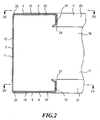
- FIG. 2 shows a section through the leg 2 along the line II from FIG. 1.
- the C-profiles 4 and 5 are cut. It is the main pages 10 and 11, the connecting sides 12 and 13 and the secondary sides 14 and 15 of the two C-profiles 4 and 5 can be seen.
- the claws 8 and 9 are each on the connecting surface 13 or 12 flat.
- the main surface 31 of the claw 8 lies on the connection side 13 on.
- the main surface 32 of the claw 9 lies on the connection side 12 on.
- a secondary leg 27 of the claw 8 forms a 90 ° angle with the main surface 31.
- the lower leg lies against the secondary side 15.
- the lower leg 27 is jagged at the end.
- the end 15 has a bend at the end on which the jagged side leg 27 braces and claws.
- the side 14 of the C-profile 4 has an inward direction Main page 10 directional bend. This bend tightens jagged side leg 29.
- the side leg 29 of the claw 9 has a 90 ° angle to the main surface 32 of the claw 9.
- the side leg 29 runs parallel to the main page 10.
- the main leg 23 is braced in the main page 11.
- the main leg 25 tensions in the main side 10.
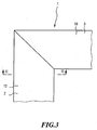
- FIG. 3 shows the legs 2 and 3 in a plan view along the line III from FIG. 2 the kit 1 with their connecting sides 12 and 18 can be seen.
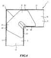
- FIG. 4 shows a longitudinal section through the kit 1 from FIG. 2.
- the claw 8 has the main legs 23 and 24.
- This Main legs 23 and 24 are jagged.
- the main leg 23 braced in the main page 11.
- a main leg 24 of the claw 8 is clamped in the Main side 17.
- a main surface 31 of the claw 8 has a recess 33. This Recess 33 enables simple insertion into legs 2 and 3.
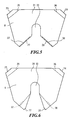
- Fig. 5 shows a claw 8, which is identical to a claw 9. Just the position Type of use and / or location in the kit is different.
- the claw 8 has a metal one Body on.
- the claw 8 contains a main surface 31, a recess 33 and the main legs 23 and 24.
- the main legs 23 and 24 are designed jagged.
- the main legs 23 and 24 have bending lines 35 and 36.
- the main legs 23 and 24 are along the bend lines 35 and 36 at a 5 ° angle to the main surface 31 bent upwards.
- the lower legs 27 and 28, which are jagged, are in this embodiment along the bending lines 37 and 38 at a 90 ° angle bent up to the main surface 31.
- FIG. 6 shows the claw 8. It has the main legs 23 and 24 running along it of the bending lines 35 and 36 of the main surface 31 are designed to be bendable.
- the side legs 27 and 28 are designed to be bendable along the bending lines 37 and 38.
- a recess 33 is kept free from the main surface 31.
- FIG. 7 shows the angle ⁇ , which, as described in FIG. 5, comprises 5 °.
- the Claw 8 has the lower leg 27.
- the bending line 37 is between the lower leg 27 and the main surface 31 can be seen.
- the bending line 35, between the The main leg 23 and the main surface 31 of the claw 8 can also be seen.
- Fig. 8 the claw 8 is shown in a rear view from which the angle ⁇ is measured between a plane through the major surface 31 and a plane through either the main leg 23 or through the main leg 24 can be seen.
- the bending lines 35 and 36 are between the main surface 31 and the main leg 23 on the one hand and the main surface 31 and the main leg 24 on the other hand.
- the lower legs 27 and 28 can also be seen.
- FIG. 9 is a rear perspective view of the kit.
- the main pages 16 and 17 of the leg 3 are along the bending line 22 with the main sides 10 and 11 of the leg 2 connected.
Landscapes
- Engineering & Computer Science (AREA)
- Civil Engineering (AREA)
- Structural Engineering (AREA)
- Architecture (AREA)
- Physics & Mathematics (AREA)
- Electromagnetism (AREA)
- Tents Or Canopies (AREA)
- Toys (AREA)
Applications Claiming Priority (2)
| Application Number | Priority Date | Filing Date | Title |
|---|---|---|---|
| DE2002117574 DE10217574B3 (de) | 2002-04-19 | 2002-04-19 | Bausatz mit Eckverbinder |
| DE10217574 | 2002-04-19 |
Publications (1)
| Publication Number | Publication Date |
|---|---|
| EP1355012A2 true EP1355012A2 (fr) | 2003-10-22 |
Family
ID=28458934
Family Applications (1)
| Application Number | Title | Priority Date | Filing Date |
|---|---|---|---|
| EP20030007180 Withdrawn EP1355012A2 (fr) | 2002-04-19 | 2003-03-28 | Kit avec élément de connection d'angle |
Country Status (2)
| Country | Link |
|---|---|
| EP (1) | EP1355012A2 (fr) |
| DE (1) | DE10217574B3 (fr) |
Cited By (4)
| Publication number | Priority date | Publication date | Assignee | Title |
|---|---|---|---|---|
| WO2023186238A1 (fr) * | 2022-03-31 | 2023-10-05 | Vkr Holding A/S | Fenêtre de toit comprenant un châssis à éléments de profil et procédé de fabrication d'une fenêtre de toit |
| CN118669399A (zh) * | 2024-08-23 | 2024-09-20 | 江苏博诚金属制品有限公司 | 一种多功能紧固件 |
| USD1052757S1 (en) | 2023-03-30 | 2024-11-26 | Vkr Holding A/S | Window |
| USD1065597S1 (en) | 2023-03-30 | 2025-03-04 | Vkr Holding A/S | Window component |
Family Cites Families (10)
| Publication number | Priority date | Publication date | Assignee | Title |
|---|---|---|---|---|
| DE7418811U (de) * | 1974-11-07 | Kemhadjian P | Im wesentlichen aus L-förmig profilierten Profilleistenabschnitten gebildeter Bilderrahmen | |
| US2717667A (en) * | 1953-10-01 | 1955-09-13 | Joseph C Bancroft | Window frame construction |
| GB1084298A (en) * | 1965-06-14 | 1967-09-20 | The Schlegel Manufacturing Company | Garnishing bead miter joint and method of making same |
| DE1982150U (de) * | 1967-11-28 | 1968-03-28 | Loeffler & Ross K G Metallbau | Eckverbindung fuer leichtmetallprofile. |
| US4240765A (en) * | 1979-04-27 | 1980-12-23 | Offterdinger Hermann F | Corner construction |
| WO1984002559A1 (fr) * | 1982-12-29 | 1984-07-05 | Japan Art Kikaku Co Ltd | Dispositif de couplage pour cadre façonne |
| DE4112181A1 (de) * | 1991-04-13 | 1992-10-15 | Elram Wintergartentechnik Gmbh | Stossverbindung von u-profilen, insbesondere u-profilen aus metall fuer die errichtung eines wintergartens |
| US5201787A (en) * | 1991-05-31 | 1993-04-13 | Usg Interiors, Inc. | Trim system for suspension ceilings |
| FR2701510B1 (fr) * | 1993-02-15 | 1995-04-21 | Alcan France | Equerre d'affleurement pour chassis de fenêtre ou analogue en profilés métalliques. |
| DE10126278C2 (de) * | 2001-05-29 | 2003-06-12 | Wicona Bausysteme Gmbh | Hinterlegungsbauteil |
-
2002
- 2002-04-19 DE DE2002117574 patent/DE10217574B3/de not_active Expired - Fee Related
-
2003
- 2003-03-28 EP EP20030007180 patent/EP1355012A2/fr not_active Withdrawn
Cited By (5)
| Publication number | Priority date | Publication date | Assignee | Title |
|---|---|---|---|---|
| WO2023186238A1 (fr) * | 2022-03-31 | 2023-10-05 | Vkr Holding A/S | Fenêtre de toit comprenant un châssis à éléments de profil et procédé de fabrication d'une fenêtre de toit |
| US12320119B2 (en) | 2022-03-31 | 2025-06-03 | Vkr Holding A/S | Roof window comprising a sash with profile elements and method of manufacturing a roof window |
| USD1052757S1 (en) | 2023-03-30 | 2024-11-26 | Vkr Holding A/S | Window |
| USD1065597S1 (en) | 2023-03-30 | 2025-03-04 | Vkr Holding A/S | Window component |
| CN118669399A (zh) * | 2024-08-23 | 2024-09-20 | 江苏博诚金属制品有限公司 | 一种多功能紧固件 |
Also Published As
| Publication number | Publication date |
|---|---|
| DE10217574B3 (de) | 2004-02-19 |
Similar Documents
| Publication | Publication Date | Title |
|---|---|---|
| EP0274085B1 (fr) | Pince-papier en matière plastique | |
| DE69318556T2 (de) | Klemmbacke | |
| EP2059146B1 (fr) | Tiroir | |
| CH681383A5 (fr) | ||
| DE60204852T2 (de) | Verbindungsschiene für draht-kabelwannen, draht-kabelwannen, die mit einer solchen verbvindungsschiene versehen sind, und eine einheit aus draht-kabelwannen, die durch eine solche verbindungsschiene verbunden sind | |
| DE2915460A1 (de) | Palette mit laengstraegerelementen und tragflaechenelementen | |
| EP0404726A2 (fr) | Dispositif pour la connexion de rails en forme de C, en particulier rails de montage | |
| DE202022104613U1 (de) | Eckverbinder | |
| EP1355012A2 (fr) | Kit avec élément de connection d'angle | |
| EP1508654A1 (fr) | Profilé creux pour attacher des objets | |
| DE202024101445U1 (de) | Drahtgitter-Fachboden für eine Regalanlage in einem Warenlager | |
| DE10324160B4 (de) | Vorrichtung zum Verbinden von Flansche aufweisende Luftkanalabschnitte | |
| EP1500827A1 (fr) | Système de construction modulaire | |
| EP0961039A1 (fr) | Dispositif de fixation | |
| EP1381739A1 (fr) | Assemblage en t de deux profiles | |
| DE841499C (de) | Bauteil in Form einer U-Schiene | |
| DE2142621A1 (de) | Verbindung von rechteckprofilen | |
| EP0028606A1 (fr) | Dispositif de liaison pour elements plans de construction | |
| DE202007008901U1 (de) | Profilverbinder und Verkleidung | |
| DE102020132662A1 (de) | T-Verbindung für Pfosten-Riegel-Konstruktionen und Pfosten- Riegel-Konstruktion mit einer derartigen T-Verbindung | |
| DE19901050C2 (de) | Halterung zur Anordnung von Bauelementen | |
| DE19852133A1 (de) | Abstandshalter | |
| DE102015105481A1 (de) | Profilverbinder | |
| DE19503429B4 (de) | Vorrichtung für das stirnseitige Verbinden von Kabelbahnen | |
| DE2915276C3 (de) | Verbindung für Flächenkonstruktionselemente |
Legal Events
| Date | Code | Title | Description |
|---|---|---|---|
| PUAI | Public reference made under article 153(3) epc to a published international application that has entered the european phase |
Free format text: ORIGINAL CODE: 0009012 |
|
| AK | Designated contracting states |
Kind code of ref document: A2 Designated state(s): AT BE BG CH CY CZ DE DK EE ES FI FR GB GR HU IE IT LI LU MC NL PT SE SI SK TR |
|
| AX | Request for extension of the european patent |
Extension state: AL LT LV MK RO |
|
| STAA | Information on the status of an ep patent application or granted ep patent |
Free format text: STATUS: THE APPLICATION HAS BEEN WITHDRAWN |
|
| 18W | Application withdrawn |
Effective date: 20091204 |