EP1355079A1 - Schauchrollbalg-Luftfeder - Google Patents
Schauchrollbalg-Luftfeder Download PDFInfo
- Publication number
- EP1355079A1 EP1355079A1 EP03002426A EP03002426A EP1355079A1 EP 1355079 A1 EP1355079 A1 EP 1355079A1 EP 03002426 A EP03002426 A EP 03002426A EP 03002426 A EP03002426 A EP 03002426A EP 1355079 A1 EP1355079 A1 EP 1355079A1
- Authority
- EP
- European Patent Office
- Prior art keywords
- bellows
- diameter
- rolling
- hose
- piston
- Prior art date
- Legal status (The legal status is an assumption and is not a legal conclusion. Google has not performed a legal analysis and makes no representation as to the accuracy of the status listed.)
- Granted
Links
- 238000005096 rolling process Methods 0.000 title claims description 37
- 239000011324 bead Substances 0.000 claims abstract description 12
- 230000003993 interaction Effects 0.000 abstract 1
- 230000006378 damage Effects 0.000 description 2
- 208000036590 Maladministrations Diseases 0.000 description 1
- 230000004323 axial length Effects 0.000 description 1
- 230000006835 compression Effects 0.000 description 1
- 238000007906 compression Methods 0.000 description 1
- 230000002349 favourable effect Effects 0.000 description 1
- 238000012423 maintenance Methods 0.000 description 1
- 238000004519 manufacturing process Methods 0.000 description 1
- 230000007704 transition Effects 0.000 description 1
Images


Classifications
-
- F—MECHANICAL ENGINEERING; LIGHTING; HEATING; WEAPONS; BLASTING
- F16—ENGINEERING ELEMENTS AND UNITS; GENERAL MEASURES FOR PRODUCING AND MAINTAINING EFFECTIVE FUNCTIONING OF MACHINES OR INSTALLATIONS; THERMAL INSULATION IN GENERAL
- F16F—SPRINGS; SHOCK-ABSORBERS; MEANS FOR DAMPING VIBRATION
- F16F9/00—Springs, vibration-dampers, shock-absorbers, or similarly-constructed movement-dampers using a fluid or the equivalent as damping medium
- F16F9/02—Springs, vibration-dampers, shock-absorbers, or similarly-constructed movement-dampers using a fluid or the equivalent as damping medium using gas only or vacuum
- F16F9/04—Springs, vibration-dampers, shock-absorbers, or similarly-constructed movement-dampers using a fluid or the equivalent as damping medium using gas only or vacuum in a chamber with a flexible wall
- F16F9/0454—Springs, vibration-dampers, shock-absorbers, or similarly-constructed movement-dampers using a fluid or the equivalent as damping medium using gas only or vacuum in a chamber with a flexible wall characterised by the assembling method or by the mounting arrangement, e.g. mounting of the membrane
Definitions
- the invention relates to a hose bellows air spring according to the genus Main claim.
- a conventional hose bellows has a cylindrical wall which is axially attached to a rolling piston. All known hose bellows air spring types work only when pressurized. In the depressurized state, it is not possible to roll the hose bellows on the roll-off piston. A depressurized state can e.g. B. occur during maintenance work. If a vehicle is lifted on a lifting platform, the air springs are pulled apart (relieved of the vehicle weight and pulled by the axle weight). If the vehicle is then lowered again with pressureless air springs, uncontrollable compressions result in conventional hose rolling bellows, which result in damage to the destruction of the air spring.
- EP 0 548 581 B1 describes a hose bellows air spring of the generic type, where the bellows clamping is not - as usual - aligned axially but radially (see for example Fig. 1 and Fig. 4).
- Has the radial alignment of the roll bellows attachment the advantage that only a 90 ° deflection is required for the rolling process becomes.
- the exit from the restraint oriented transversely to the axis causes - alone considered - not yet a prerequisite for unpressurized rolling.
- EP 0 548 581 B1, Fig. 1, aptly describes the facts (unpressurized: solid lines; pressurized: dashed lines). When depressurized (solid lines) there is a sharp bend in the radial from the attachment escaping roll bellows.
- solid lines solid lines
- the object of the invention is this - especially in the depressurized state given - to remedy maladministration. Even in a depressurized state, it should be flawless Rolling of the bellows on the piston wall must be guaranteed.
- the hose bellows has a - preferably at least at its fastening end conical - tapering on, with the clamping area having a smaller diameter is provided, while the remaining bellows body has a larger diameter with a cylindrical Has shape. Due to the special type of clamping at the end of the rolling piston the bellows deflection is only approx. 90 °.
- the outer diameter corresponds to this of the bulge located at the piston end approximately the rolling diameter of the Piston.
- the outer diameter of the bead corresponds approximately to that Outside diameter of the clamped clamping ring.
- the diameter difference between the bellows and the rolling piston is approximately equal to eight times the wall thickness of the bellows, the wall thickness of the bellows being approximately 1.5 to 6 mm, ie: D D - D K ⁇ 12 to 48 mm.
- the conical area of the bellows is smaller than twice the difference in diameter between the bellows and the rolling piston, ie: Lü ⁇ 24 to 96 mm.
- the product of the roll bellows diameter and roll bellows wall thickness is larger than the cylindrical roll bellows length, ie: L cyl ⁇ 1.5 D D to 6 D D [mm].
- the invention Air spring achieves a more favorable rolling behavior, especially when the air spring is depressurized.
- force is exerted on the unwinding piston, pressure-free folding is maintained a small rolling radius possible.
- the Balges avoided.
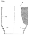
- the hose bellows 4 according to the invention shown in FIG. 1 has - as in Hose bellows common - no end beads on. This makes it possible Manufacture hose bellows as sections of an endless hose. While conventional tubular roller bellows are designed purely cylindrical, the hose bellows 4 according to the invention on its "lower", the rolling piston end facing an approximately conical taper (conical area, 32). The The taper is already in the untensioned, depressurized state. The upper" Area 18 of the tubular bellows 4 is - as with conventional tubular bellows - cylindrical.
- Fig. 2 shows the same hose bellows 4, but in the installed state, ie as part of an air spring 2.
- the bellows 4 is on a cover (cover plate) 8 and at its “lower” end on a rolling piston 6 attached pressure-tight with a clamping ring 12a, 12b.
- the tapering shape and the type of clamping on the unwinding piston 6 have the consequence that the hose bellows 4 already leaves the clamping point on the unwinding piston 6 almost at a right angle in the unpressurized state.
- “L zy1 " indicates the cylindrical region 18 of the hose bellows 4, while “L ü " means the axial length of the approximately conical region 32.
- D D denotes the diameter of the cylindrical region 18;
- D K is the diameter of the rolling piston 6.
- 30 denotes the wall thickness of the hose bellows 4.
- FIG. 3 shows the same basic structure of an air spring 2, consisting of cover plate 8, Rolling bellows 4 and rolling piston 6.
- the bellows 4 is correspondingly inflated to the outside (left side).
- the right side of FIG. 3 represents the compressed state of the pressurized air spring 2.
- the “upper” region 18 of the tubular bellows 4 is cylindrical (L cyl ).
- the cylindrical portion 18 of the approximately conical (transition) zone (L ü) 32 is followed by downward.
- the roller bellows 4 is clamped pressure-tight by means of a clamping ring on the (top) cover plate (cover) 8.
- the lower end of the hose bellows 4 is also attached pressure-tight and tensile to the rolling piston 6 by means of a clamping ring 12b.
- the rolling piston 6 has a circumferential recess (groove) 10 at its upper end.
- This depression 10 serves to receive the lower end of the hose bellows 4, on which the clamping ring 12b is placed and compressed on all sides.
- the circumferential recess (groove) 10 is delimited by a bead 14 which forms the upper edge of the rolling piston 6.
- the outer diameter 20 of the bead 14 corresponds approximately to the outer diameter 24 of the clamping ring 12b and also the rolling diameter (D K ) 22 of the piston 6.
Landscapes
- Engineering & Computer Science (AREA)
- General Engineering & Computer Science (AREA)
- Mechanical Engineering (AREA)
- Fluid-Damping Devices (AREA)
- Sealing Devices (AREA)
- Diaphragms And Bellows (AREA)
- Fertilizers (AREA)
- Devices And Processes Conducted In The Presence Of Fluids And Solid Particles (AREA)
- Air-Flow Control Members (AREA)
Abstract
Description
Ein druckloser Zustand kann z. B. bei Wartungsarbeiten auftreten. Wird ein Fahrzeug auf einer Hebebühne angehoben, werden die Luftfedern auseinandergezogen (vom Fahrzeuggewicht entlastet und durch das Achsgewicht gezogen). Wird das Fahrzeug dann mit drucklosen Luftfedern wieder abgesetzt, ergeben sich bei herkömmlichen Schlauchrollbälgen unkontrollierbare Stauchungen, die von der Beschädigung bis hin zur Zerstörung der Luftfeder führen.
Der konische Bereich des Rollbalgs ist kleiner als die doppelte Durchmesser-Differenz von Rollbalg und Abrollkolben, d. h.: Lü < 24 bis 96 mm.
Das Produkt aus Rollbalgdurchmesser und Rollbalg-Wandstärke ist größer als die zylindrische Rollbalg-Länge, d. h.: LZyl < 1,5 DD bis 6 DD [mm].
"Lzy1" gibt den zylindrischen Bereich 18 des Schlauchrollbalges 4 an, während "Lü" die axiale Länge des in etwa konischen Bereichs 32 bedeutet. Mit "DD" ist der Durchmesser des zylindrischen Bereichs 18 bezeichnet; "DK" ist der Durchmesser des Abrollkolbens 6. "30" bezeichnet die Wandstärke des Schlauchrollbalgs 4.
Das unter Ende des Schlauchrollbalgs 4 ist mittels eines Klemmringes 12b am Abrollkolben 6 ebenfalls druckdicht und zugfest angebracht. Zwecks Befestigung des Schlauchrollbalgs 4 weist der Abrollkolben 6 an seinem oberen Ende eine umlaufende Vertiefung (Nut) 10 auf.
Diese Vertiefung 10 dient zur Aufnahme des unteren Endes des Schlauchrollbalgs 4, auf den der Klemmring 12b aufgesetzt und allseits zusammengedrückt wird.
Die umlaufende Vertiefung (Nut) 10 wird von einem Wulst 14 begrenzt, der den oberen Rand des Abrollkolbens 6 bildet. Der Außendurchmesser 20 des Wulstes 14 entspricht annähernd dem Außendurchmesser 24 des Klemmringes 12b und außerdem dem Abrolldurchmesser (DK) 22 des Kolbens 6. Die umlaufende Vertiefung (=Einspannbereich) 10 und der Wulst 14 sind so ausgebildet, dass (bereits) im drucklosen Zustand ein eindeutiger Durchmessersprung zwischen dem zylindrischen Durchmesser (DK) 28 des zylindrischen Balgbereichs 18 und dem Durchmesser 26 im Spannbereich des Balges 4 am Kolben 6 vorliegt, wodurch das mittels Klemmring 12b eingespannte Rollbalg-Ende um 90° abgelenkt wird und senkrecht (radial) nach außen gerichtet ist.
- 2
- Luftfeder
- 4
- Schlauchrollbalg, Rollbalg
- 6
- Abrollkolben
- 8
- Abdeckplatte
- 10
- Vertiefung, Nut, Einspannbereich
- 12a, 12b
- Klemmring
- 14
- Wulst
- 16
- (konische) Verjüngung des Rollbalgs
- 18
- zylindrischer Bereich des Rollbalgs (LZyl)
- 20
- Außendurchmesser des Wulstes
- 22
- Abrolldurchmesser des Kolbens (DK)
- 24
- Außendurchmesser des Klemmringes
- 26
- Einspanndurchmesser des Balgs
- 28
- Balgdurchmesser im zylindrischen Bereich, übriger Balgdurchmesser (DD)
- 30
- Wandstärke des Rollbalgs
- 32
- konische Länge (konischer Bereich) des Rollbalgs (LÜ)
Claims (5)
- Schlauchrollbalg-Luftfeder (2),dadurch gekennzeichnet, dass der Schlauchrollbalg (4) zumindest an seinem unteren Bereich (32) eine konische Verjüngung (16) aufweist, wodurch im Zusammenwirken mit den den Einspannbereich betreffenden Merkmalen bereits im drucklosen Zustand der Luftfeder (2) ein in etwa radiales (90°-)Austreten des Balges (4) aus der Rollbalgbefestigung realisiert ist.bestehend aus einem Schlauchrollbalg (4), einer Abdeckplatte (8) und einem Abrollkolben (6),wobei der Abrollkolben (6) an seinem oberen Ende eine umlaufende Vertiefung (Nut, 10) zur Aufnahme des mittels eines außen aufgesetzten Klemmringes (12b) druckdicht und zugfest aufzubringenden Rollbalg-Endes und einen Wulst (14) zur Umlenkung des Rollbalgs (4) aufweist, undwobei der Außendurchmesser (20) des Wulstes (14) annähernd dem Außendurchmesser (24) des geklemmten Klemmringes (12b) und dem Abrolldurchmesser (DK, 22) des Kolbens (6) entspricht,
- Schlauchrollbalg-Luftfeder nach Anspruch 1,
dadurch gekennzeichnet, dass die umlaufende Vertiefung (=Einspannbereich, 10) und der Wulst (14) so ausgebildet sind, dass im drucklosen Zustand ein eindeutiger Durchmessersprung zwischen Einspanndurchmesser (26) und übrigem Balgdurchmesser (DD, 28) vorliegt. - Schlauchrollbalg-Luftfeder nach Anspruch 1 oder 2,
dadurch gekennzeichnet, dass die Durchmesser-Differenz von Rollbalg (4) und Abrollkolben (6) ungefähr gleich dem Achtfachen der Wandstärke (30) des Rollbalgs (4) ist, wobei die Wandstärke (30) des Rollbalgs (4) ca. 1,5 bis 6 mm beträgt, d. h. DD- DK = 12 bis 48 mm. - Schlauchrollbalg-Luftfeder nach einem der Ansprüche 1 bis 3,
dadurch gekennzeichnet, dass der sich verjüngende Bereich (LÜ, 32) des Rollbalgs (4) kleiner als die doppelte Durchmesser-Differenz von Rollbalg (4) und Abrollkolben (6) ist, d. h.: LÜ < 24 bis 96 mm. - Schlauchrollbalg-Luftfeder nach einem der Ansprüche 1 bis 4,
dadurch gekennzeichnet, dass das Produkt aus Rollbalg-Durchmesser (DD, 28) und Rollbalgwandstärke (30) pro mm größer ist als die zylindrische Rollbalglänge (LZyl, 18), d. h.: LZyl < 1,5 DD bis 6 DD [mm].
Applications Claiming Priority (2)
| Application Number | Priority Date | Filing Date | Title |
|---|---|---|---|
| DE10216750A DE10216750A1 (de) | 2002-04-16 | 2002-04-16 | Schlauchrollbalg-Luftfeder |
| DE10216750 | 2002-04-16 |
Publications (2)
| Publication Number | Publication Date |
|---|---|
| EP1355079A1 true EP1355079A1 (de) | 2003-10-22 |
| EP1355079B1 EP1355079B1 (de) | 2005-09-14 |
Family
ID=28458854
Family Applications (1)
| Application Number | Title | Priority Date | Filing Date |
|---|---|---|---|
| EP03002426A Expired - Lifetime EP1355079B1 (de) | 2002-04-16 | 2003-02-05 | Schauchrollbalg-Luftfeder |
Country Status (5)
| Country | Link |
|---|---|
| US (1) | US7226044B2 (de) |
| EP (1) | EP1355079B1 (de) |
| AT (1) | ATE304670T1 (de) |
| DE (2) | DE10216750A1 (de) |
| ES (1) | ES2248651T3 (de) |
Cited By (3)
| Publication number | Priority date | Publication date | Assignee | Title |
|---|---|---|---|---|
| DE10354574B3 (de) * | 2003-11-21 | 2005-01-27 | Contitech Luftfedersysteme Gmbh | Luftfeder mit einem wulstlosen Schlauchrollbalg |
| EP2060832A2 (de) | 2007-11-16 | 2009-05-20 | Continental Aktiengesellschaft | Klemmkontur für ein druckbeaufschlagbares Bauteil und Spannmittel dafür |
| EP2524828A1 (de) * | 2011-05-17 | 2012-11-21 | Carl Freudenberg KG | Lager sowie Lageranordnung |
Families Citing this family (6)
| Publication number | Priority date | Publication date | Assignee | Title |
|---|---|---|---|---|
| DE102004054205A1 (de) * | 2004-11-10 | 2006-05-11 | Zf Friedrichshafen Ag | Luftfeder |
| DE102005041800B3 (de) * | 2005-09-02 | 2007-03-01 | Otto Sauer Achsenfabrik Gmbh | Luftfederbalg |
| RU2520643C2 (ru) * | 2009-09-17 | 2014-06-27 | ФАЙРСТОУН ИНДАСТРИАЛ ПРОДАКТС КОМПАНИ, ЭлЭлСи | Гибкая втулка, содержащий ее узел газовой пружины и способ его сборки |
| EP2488770B1 (de) * | 2009-10-14 | 2022-12-14 | Firestone Industrial Products Company, LLC | Endteil, gasfederanordnung und verfahren |
| US8733743B2 (en) * | 2010-12-23 | 2014-05-27 | Firestone Industrial Products Company, Llc | Gas spring piston, gas spring assembly and method |
| DE112020001936T5 (de) * | 2019-04-15 | 2022-01-13 | ILJIN USA Corporation | Luftfedern und verfahren zur herstellung derselben |
Citations (4)
| Publication number | Priority date | Publication date | Assignee | Title |
|---|---|---|---|---|
| DE2050613A1 (de) * | 1970-10-15 | 1972-04-20 | Continental Gummi Werke Ag | Luftfederbalg |
| EP0548581A1 (de) * | 1991-12-21 | 1993-06-30 | Continental Aktiengesellschaft | Luftfeder mit einem wulstlosen Luftfederbalg aus elastomerem Werkstoff |
| WO2000043692A1 (de) * | 1999-01-21 | 2000-07-27 | Phoenix Aktiengesellschaft | Luftfedersystem |
| EP1031756A2 (de) * | 1999-02-23 | 2000-08-30 | Bayerische Motoren Werke Aktiengesellschaft | Befestigung eines Luftfeder-Rollbalges an einem Stützteil |
Family Cites Families (13)
| Publication number | Priority date | Publication date | Assignee | Title |
|---|---|---|---|---|
| JPS62167943A (ja) * | 1986-01-21 | 1987-07-24 | Bridgestone Corp | 空気ばね |
| DE3643073A1 (de) * | 1986-12-17 | 1988-06-30 | Phoenix Ag | Luftfeder |
| US5005808A (en) * | 1987-12-01 | 1991-04-09 | The Goodyear Tire & Rubber Company | Airspring end member and airspring assembly |
| US4899995A (en) * | 1988-12-29 | 1990-02-13 | Bridgestone/Firestone, Inc. | Clamp ring assembly for air spring |
| US4946144A (en) * | 1989-03-30 | 1990-08-07 | Bridgestone/Firestone, Inc. | External clamping band for air spring |
| US5374037A (en) * | 1993-09-20 | 1994-12-20 | Bridgestone/Firestone, Inc. | Clamp ring assembly for air spring |
| US6439550B1 (en) * | 1997-02-18 | 2002-08-27 | Bfs Diversified Products, Llc | Adhesive laminate and method of securing a rubber air spring to a fixturing sleeve |
| NZ512729A (en) * | 1999-01-04 | 2003-10-31 | Sauer Achsenfab | Vehicle axle suspension |
| MXPA02000370A (es) * | 1999-06-11 | 2004-05-21 | Gates Corp | Muelle de aire de compartimiento dual. |
| DE19959011A1 (de) * | 1999-12-08 | 2001-06-13 | Contitech Luftfedersyst Gmbh | Dichte Befestigung eines Luftfederbalges |
| US6474630B1 (en) * | 2001-04-24 | 2002-11-05 | Bfs Diversified Products, Llc | Air spring swage assembly |
| DE10249741A1 (de) * | 2002-10-25 | 2004-05-06 | Continental Aktiengesellschaft | Rollbalg-Luftfeder mit Stützglocke |
| DE102004056517A1 (de) * | 2004-11-24 | 2006-06-01 | Contitech Luftfedersysteme Gmbh | Tiefbettklemmkontur für Schlauchrollbalg-Luftfedern |
-
2002
- 2002-04-16 DE DE10216750A patent/DE10216750A1/de not_active Withdrawn
-
2003
- 2003-02-05 ES ES03002426T patent/ES2248651T3/es not_active Expired - Lifetime
- 2003-02-05 DE DE50301165T patent/DE50301165D1/de not_active Expired - Lifetime
- 2003-02-05 AT AT03002426T patent/ATE304670T1/de not_active IP Right Cessation
- 2003-02-05 EP EP03002426A patent/EP1355079B1/de not_active Expired - Lifetime
- 2003-04-16 US US10/414,052 patent/US7226044B2/en not_active Expired - Lifetime
Patent Citations (4)
| Publication number | Priority date | Publication date | Assignee | Title |
|---|---|---|---|---|
| DE2050613A1 (de) * | 1970-10-15 | 1972-04-20 | Continental Gummi Werke Ag | Luftfederbalg |
| EP0548581A1 (de) * | 1991-12-21 | 1993-06-30 | Continental Aktiengesellschaft | Luftfeder mit einem wulstlosen Luftfederbalg aus elastomerem Werkstoff |
| WO2000043692A1 (de) * | 1999-01-21 | 2000-07-27 | Phoenix Aktiengesellschaft | Luftfedersystem |
| EP1031756A2 (de) * | 1999-02-23 | 2000-08-30 | Bayerische Motoren Werke Aktiengesellschaft | Befestigung eines Luftfeder-Rollbalges an einem Stützteil |
Cited By (4)
| Publication number | Priority date | Publication date | Assignee | Title |
|---|---|---|---|---|
| DE10354574B3 (de) * | 2003-11-21 | 2005-01-27 | Contitech Luftfedersysteme Gmbh | Luftfeder mit einem wulstlosen Schlauchrollbalg |
| EP2060832A2 (de) | 2007-11-16 | 2009-05-20 | Continental Aktiengesellschaft | Klemmkontur für ein druckbeaufschlagbares Bauteil und Spannmittel dafür |
| DE102007055077A1 (de) | 2007-11-16 | 2009-05-20 | Continental Aktiengesellschaft | Klemmkontur für ein druckbeaufschlagbares Bauteil und Spannmittel dafür |
| EP2524828A1 (de) * | 2011-05-17 | 2012-11-21 | Carl Freudenberg KG | Lager sowie Lageranordnung |
Also Published As
| Publication number | Publication date |
|---|---|
| DE50301165D1 (de) | 2005-10-20 |
| US7226044B2 (en) | 2007-06-05 |
| US20050280193A1 (en) | 2005-12-22 |
| ATE304670T1 (de) | 2005-09-15 |
| EP1355079B1 (de) | 2005-09-14 |
| ES2248651T3 (es) | 2006-03-16 |
| DE10216750A1 (de) | 2003-10-30 |
Similar Documents
| Publication | Publication Date | Title |
|---|---|---|
| DE69400330T2 (de) | Befestigungsring für eine pneumatische Feder | |
| DE60012394T2 (de) | Nichtmetallische Zwischenplatte für eine Luftfeder | |
| EP4098432B1 (de) | Radialpresse | |
| DE60009719T2 (de) | Durch hochdruckumformen hergestellte verformbare antriebswelle und lenksäule und verfahren zur herstellung derselben | |
| EP1140529B1 (de) | Fahrzeug-achsaufhängung | |
| EP0151696A1 (de) | Luftfederung insbesondere für Strassenfahrzeuge | |
| DE4135900C2 (de) | Luftfeder, insbesondere für Kraftfahrzeuge | |
| EP2090801A1 (de) | Luftfeder-Rollbalg | |
| DE69721969T2 (de) | Klemmvorrichtung für pneumatisches Stellelement | |
| EP2847487B1 (de) | Luftfeder und verfahren zum umschlagen eines luftfederbalges einer luftfeder | |
| EP1693233A1 (de) | Luftfederbein mit zentrisch angeordnetem Dämpfer | |
| EP1355079A1 (de) | Schauchrollbalg-Luftfeder | |
| EP1321694A2 (de) | Schlauchrollbalg-Feder | |
| DE4006480A1 (de) | Rollbalg-luftfeder mit einem schlauchrollbalg aus elastomerem werkstoff | |
| DE19533479C2 (de) | Fahrzeugachse | |
| EP1064474A1 (de) | Luftfedersystem | |
| DE19645228C2 (de) | Luftfeder mit Abrollkörper | |
| EP1321693A1 (de) | Doppelrollbalg-Federungseinrichtung | |
| DE2845266C2 (de) | Sicherheitsfeststellbremse für hydraulische Aufzüge, Hebebühnen u.dgl. | |
| EP0865373A1 (de) | Einstellbare lenkeinrichtung | |
| DE4008513C2 (de) | Notlaufstützkörper für einen Luftreifen und Kraftfahrzeugrad | |
| DE102004015248A1 (de) | Aufzughülse für einen Druckwerkzylinder einer Offsetdruckmaschine | |
| DE102004015602B4 (de) | Luftfedereinrichtung | |
| WO2005024265A1 (de) | Befestigung eines luftfeder-rollbalgs an einer armatur | |
| DE102011056338B4 (de) | Verfahren zum Hochschlagen eines Reifenaufbauteiles auf einer Reifenaufbautrommel zur Herstellung von Reifenrohlingen |
Legal Events
| Date | Code | Title | Description |
|---|---|---|---|
| PUAI | Public reference made under article 153(3) epc to a published international application that has entered the european phase |
Free format text: ORIGINAL CODE: 0009012 |
|
| AK | Designated contracting states |
Kind code of ref document: A1 Designated state(s): AT BE BG CH CY CZ DE DK EE ES FI FR GB GR HU IE IT LI LU MC NL PT SE SI SK TR |
|
| AX | Request for extension of the european patent |
Extension state: AL LT LV MK RO |
|
| 17P | Request for examination filed |
Effective date: 20040422 |
|
| 17Q | First examination report despatched |
Effective date: 20040524 |
|
| AKX | Designation fees paid |
Designated state(s): AT BE BG CH CY CZ DE DK EE ES FI FR GB GR HU IE IT LI LU MC NL PT SE SI SK TR |
|
| GRAP | Despatch of communication of intention to grant a patent |
Free format text: ORIGINAL CODE: EPIDOSNIGR1 |
|
| GRAS | Grant fee paid |
Free format text: ORIGINAL CODE: EPIDOSNIGR3 |
|
| GRAA | (expected) grant |
Free format text: ORIGINAL CODE: 0009210 |
|
| AK | Designated contracting states |
Kind code of ref document: B1 Designated state(s): AT BE BG CH CY CZ DE DK EE ES FI FR GB GR HU IE IT LI LU MC NL PT SE SI SK TR |
|
| PG25 | Lapsed in a contracting state [announced via postgrant information from national office to epo] |
Ref country code: SK Free format text: LAPSE BECAUSE OF FAILURE TO SUBMIT A TRANSLATION OF THE DESCRIPTION OR TO PAY THE FEE WITHIN THE PRESCRIBED TIME-LIMIT Effective date: 20050914 Ref country code: FI Free format text: LAPSE BECAUSE OF FAILURE TO SUBMIT A TRANSLATION OF THE DESCRIPTION OR TO PAY THE FEE WITHIN THE PRESCRIBED TIME-LIMIT Effective date: 20050914 Ref country code: CZ Free format text: LAPSE BECAUSE OF FAILURE TO SUBMIT A TRANSLATION OF THE DESCRIPTION OR TO PAY THE FEE WITHIN THE PRESCRIBED TIME-LIMIT Effective date: 20050914 Ref country code: SI Free format text: LAPSE BECAUSE OF FAILURE TO SUBMIT A TRANSLATION OF THE DESCRIPTION OR TO PAY THE FEE WITHIN THE PRESCRIBED TIME-LIMIT Effective date: 20050914 |
|
| REG | Reference to a national code |
Ref country code: GB Ref legal event code: FG4D Free format text: NOT ENGLISH |
|
| REG | Reference to a national code |
Ref country code: CH Ref legal event code: EP |
|
| REG | Reference to a national code |
Ref country code: IE Ref legal event code: FG4D Free format text: LANGUAGE OF EP DOCUMENT: GERMAN |
|
| REF | Corresponds to: |
Ref document number: 50301165 Country of ref document: DE Date of ref document: 20051020 Kind code of ref document: P |
|
| PG25 | Lapsed in a contracting state [announced via postgrant information from national office to epo] |
Ref country code: DK Free format text: LAPSE BECAUSE OF FAILURE TO SUBMIT A TRANSLATION OF THE DESCRIPTION OR TO PAY THE FEE WITHIN THE PRESCRIBED TIME-LIMIT Effective date: 20051214 Ref country code: GR Free format text: LAPSE BECAUSE OF FAILURE TO SUBMIT A TRANSLATION OF THE DESCRIPTION OR TO PAY THE FEE WITHIN THE PRESCRIBED TIME-LIMIT Effective date: 20051214 Ref country code: BG Free format text: LAPSE BECAUSE OF FAILURE TO SUBMIT A TRANSLATION OF THE DESCRIPTION OR TO PAY THE FEE WITHIN THE PRESCRIBED TIME-LIMIT Effective date: 20051214 |
|
| REG | Reference to a national code |
Ref country code: SE Ref legal event code: TRGR |
|
| GBT | Gb: translation of ep patent filed (gb section 77(6)(a)/1977) |
Effective date: 20060107 |
|
| PG25 | Lapsed in a contracting state [announced via postgrant information from national office to epo] |
Ref country code: AT Free format text: LAPSE BECAUSE OF NON-PAYMENT OF DUE FEES Effective date: 20060205 |
|
| PG25 | Lapsed in a contracting state [announced via postgrant information from national office to epo] |
Ref country code: PT Free format text: LAPSE BECAUSE OF FAILURE TO SUBMIT A TRANSLATION OF THE DESCRIPTION OR TO PAY THE FEE WITHIN THE PRESCRIBED TIME-LIMIT Effective date: 20060214 |
|
| PG25 | Lapsed in a contracting state [announced via postgrant information from national office to epo] |
Ref country code: MC Free format text: LAPSE BECAUSE OF NON-PAYMENT OF DUE FEES Effective date: 20060228 Ref country code: BE Free format text: LAPSE BECAUSE OF NON-PAYMENT OF DUE FEES Effective date: 20060228 Ref country code: LU Free format text: LAPSE BECAUSE OF NON-PAYMENT OF DUE FEES Effective date: 20060228 |
|
| REG | Reference to a national code |
Ref country code: HU Ref legal event code: AG4A Ref document number: E000143 Country of ref document: HU |
|
| REG | Reference to a national code |
Ref country code: ES Ref legal event code: FG2A Ref document number: 2248651 Country of ref document: ES Kind code of ref document: T3 |
|
| ET | Fr: translation filed | ||
| PLBE | No opposition filed within time limit |
Free format text: ORIGINAL CODE: 0009261 |
|
| STAA | Information on the status of an ep patent application or granted ep patent |
Free format text: STATUS: NO OPPOSITION FILED WITHIN TIME LIMIT |
|
| 26N | No opposition filed |
Effective date: 20060615 |
|
| PG25 | Lapsed in a contracting state [announced via postgrant information from national office to epo] |
Ref country code: LI Free format text: LAPSE BECAUSE OF NON-PAYMENT OF DUE FEES Effective date: 20070228 Ref country code: CH Free format text: LAPSE BECAUSE OF NON-PAYMENT OF DUE FEES Effective date: 20070228 |
|
| REG | Reference to a national code |
Ref country code: CH Ref legal event code: PL |
|
| BERE | Be: lapsed |
Owner name: CONTITECH LUFTFEDERSYSTEME G.M.B.H. Effective date: 20060228 |
|
| PG25 | Lapsed in a contracting state [announced via postgrant information from national office to epo] |
Ref country code: EE Free format text: LAPSE BECAUSE OF FAILURE TO SUBMIT A TRANSLATION OF THE DESCRIPTION OR TO PAY THE FEE WITHIN THE PRESCRIBED TIME-LIMIT Effective date: 20050914 |
|
| PG25 | Lapsed in a contracting state [announced via postgrant information from national office to epo] |
Ref country code: CY Free format text: LAPSE BECAUSE OF FAILURE TO SUBMIT A TRANSLATION OF THE DESCRIPTION OR TO PAY THE FEE WITHIN THE PRESCRIBED TIME-LIMIT Effective date: 20050914 |
|
| PGFP | Annual fee paid to national office [announced via postgrant information from national office to epo] |
Ref country code: NL Payment date: 20150218 Year of fee payment: 13 |
|
| PGFP | Annual fee paid to national office [announced via postgrant information from national office to epo] |
Ref country code: ES Payment date: 20150225 Year of fee payment: 13 |
|
| REG | Reference to a national code |
Ref country code: FR Ref legal event code: PLFP Year of fee payment: 14 |
|
| REG | Reference to a national code |
Ref country code: NL Ref legal event code: MM Effective date: 20160301 |
|
| PG25 | Lapsed in a contracting state [announced via postgrant information from national office to epo] |
Ref country code: NL Free format text: LAPSE BECAUSE OF NON-PAYMENT OF DUE FEES Effective date: 20160301 |
|
| REG | Reference to a national code |
Ref country code: FR Ref legal event code: PLFP Year of fee payment: 15 |
|
| PG25 | Lapsed in a contracting state [announced via postgrant information from national office to epo] |
Ref country code: ES Free format text: LAPSE BECAUSE OF NON-PAYMENT OF DUE FEES Effective date: 20160206 |
|
| REG | Reference to a national code |
Ref country code: FR Ref legal event code: PLFP Year of fee payment: 16 |
|
| PGFP | Annual fee paid to national office [announced via postgrant information from national office to epo] |
Ref country code: IE Payment date: 20190222 Year of fee payment: 17 |
|
| PGFP | Annual fee paid to national office [announced via postgrant information from national office to epo] |
Ref country code: BE Payment date: 20190218 Year of fee payment: 9 Ref country code: HU Payment date: 20190213 Year of fee payment: 17 |
|
| REG | Reference to a national code |
Ref country code: SE Ref legal event code: EUG |
|
| PG25 | Lapsed in a contracting state [announced via postgrant information from national office to epo] |
Ref country code: SE Free format text: LAPSE BECAUSE OF NON-PAYMENT OF DUE FEES Effective date: 20200206 |
|
| PG25 | Lapsed in a contracting state [announced via postgrant information from national office to epo] |
Ref country code: HU Free format text: LAPSE BECAUSE OF NON-PAYMENT OF DUE FEES Effective date: 20200206 |
|
| PG25 | Lapsed in a contracting state [announced via postgrant information from national office to epo] |
Ref country code: IE Free format text: LAPSE BECAUSE OF NON-PAYMENT OF DUE FEES Effective date: 20200205 |
|
| PGFP | Annual fee paid to national office [announced via postgrant information from national office to epo] |
Ref country code: TR Payment date: 20210204 Year of fee payment: 19 |
|
| PG25 | Lapsed in a contracting state [announced via postgrant information from national office to epo] |
Ref country code: IT Free format text: LAPSE BECAUSE OF NON-PAYMENT OF DUE FEES Effective date: 20200205 |
|
| PGFP | Annual fee paid to national office [announced via postgrant information from national office to epo] |
Ref country code: GB Payment date: 20220223 Year of fee payment: 20 Ref country code: DE Payment date: 20220228 Year of fee payment: 20 |
|
| PGFP | Annual fee paid to national office [announced via postgrant information from national office to epo] |
Ref country code: FR Payment date: 20220216 Year of fee payment: 20 |
|
| REG | Reference to a national code |
Ref country code: DE Ref legal event code: R071 Ref document number: 50301165 Country of ref document: DE |
|
| REG | Reference to a national code |
Ref country code: GB Ref legal event code: PE20 Expiry date: 20230204 |
|
| PG25 | Lapsed in a contracting state [announced via postgrant information from national office to epo] |
Ref country code: GB Free format text: LAPSE BECAUSE OF EXPIRATION OF PROTECTION Effective date: 20230204 |