EP2060832A2 - Klemmkontur für ein druckbeaufschlagbares Bauteil und Spannmittel dafür - Google Patents
Klemmkontur für ein druckbeaufschlagbares Bauteil und Spannmittel dafür Download PDFInfo
- Publication number
- EP2060832A2 EP2060832A2 EP20080165958 EP08165958A EP2060832A2 EP 2060832 A2 EP2060832 A2 EP 2060832A2 EP 20080165958 EP20080165958 EP 20080165958 EP 08165958 A EP08165958 A EP 08165958A EP 2060832 A2 EP2060832 A2 EP 2060832A2
- Authority
- EP
- European Patent Office
- Prior art keywords
- clamping
- component
- circumferential
- contour
- elevation
- Prior art date
- Legal status (The legal status is an assumption and is not a legal conclusion. Google has not performed a legal analysis and makes no representation as to the accuracy of the status listed.)
- Granted
Links
Images
Classifications
-
- F—MECHANICAL ENGINEERING; LIGHTING; HEATING; WEAPONS; BLASTING
- F16—ENGINEERING ELEMENTS AND UNITS; GENERAL MEASURES FOR PRODUCING AND MAINTAINING EFFECTIVE FUNCTIONING OF MACHINES OR INSTALLATIONS; THERMAL INSULATION IN GENERAL
- F16J—PISTONS; CYLINDERS; SEALINGS
- F16J3/00—Diaphragms; Bellows; Bellows pistons
- F16J3/04—Bellows
- F16J3/041—Non-metallic bellows
- F16J3/042—Fastening details
-
- F—MECHANICAL ENGINEERING; LIGHTING; HEATING; WEAPONS; BLASTING
- F16—ENGINEERING ELEMENTS AND UNITS; GENERAL MEASURES FOR PRODUCING AND MAINTAINING EFFECTIVE FUNCTIONING OF MACHINES OR INSTALLATIONS; THERMAL INSULATION IN GENERAL
- F16F—SPRINGS; SHOCK-ABSORBERS; MEANS FOR DAMPING VIBRATION
- F16F9/00—Springs, vibration-dampers, shock-absorbers, or similarly-constructed movement-dampers using a fluid or the equivalent as damping medium
- F16F9/02—Springs, vibration-dampers, shock-absorbers, or similarly-constructed movement-dampers using a fluid or the equivalent as damping medium using gas only or vacuum
- F16F9/04—Springs, vibration-dampers, shock-absorbers, or similarly-constructed movement-dampers using a fluid or the equivalent as damping medium using gas only or vacuum in a chamber with a flexible wall
- F16F9/0454—Springs, vibration-dampers, shock-absorbers, or similarly-constructed movement-dampers using a fluid or the equivalent as damping medium using gas only or vacuum in a chamber with a flexible wall characterised by the assembling method or by the mounting arrangement, e.g. mounting of the membrane
- F16F9/0463—Springs, vibration-dampers, shock-absorbers, or similarly-constructed movement-dampers using a fluid or the equivalent as damping medium using gas only or vacuum in a chamber with a flexible wall characterised by the assembling method or by the mounting arrangement, e.g. mounting of the membrane with separate crimping rings
-
- F—MECHANICAL ENGINEERING; LIGHTING; HEATING; WEAPONS; BLASTING
- F16—ENGINEERING ELEMENTS AND UNITS; GENERAL MEASURES FOR PRODUCING AND MAINTAINING EFFECTIVE FUNCTIONING OF MACHINES OR INSTALLATIONS; THERMAL INSULATION IN GENERAL
- F16J—PISTONS; CYLINDERS; SEALINGS
- F16J3/00—Diaphragms; Bellows; Bellows pistons
- F16J3/06—Bellows pistons
Definitions
- the invention relates to a clamping contour for a pressurizable component, for example a rolling piston or a connection plate of a hose roll air spring, wherein the pressurizable component has a clamping region in which it can be clamped by means of suitable clamping means with a tubular component, such as a hose roll of a hose roll air spring , And wherein at least one circumferential elevation for improving the clamping is provided in the clamping area.
- pressurized components must be connected to each other reliable and pressure-tight, so that a proper function of the component network is guaranteed.
- pressurized fluids such as water, air or oil
- Schlauchrollbalg air springs which are often used as suspension means in motor vehicles.
- a beadless tubular bladder made of elastomeric material cut from an endless tube is tightly fastened or clamped with its ends to fastening parts.
- the jamming takes place with specially designed clamping means, namely closed metallic clamping rings, which are pressed firmly by plastic, radial deformation on the wall of the hose roll bellows.
- clamping means namely closed metallic clamping rings, which are pressed firmly by plastic, radial deformation on the wall of the hose roll bellows.
- the hose rolling bellows, and thus also the fastening parts are subjected to compressed air, whereby a dynamic relative movement between the fastening parts is possible under dynamic load.
- the upper part in the operating state fastening part is generally referred to as a connection plate and the lower attachment part as a rolling piston, since this piston-like design and the Schlauchrollbalg in the resilient Relative movement between connecting plate and rolling piston rolls on the peripheral surface of the rolling piston.
- EP 1 355 079 shows a generic clamping contour for a Schlauchrollbalg air spring, which is characterized by a circumferential, trapezoidal survey.
- EP 0 379 667 A1 a specially trained in longitudinal section clamping ring which is provided in the middle of its profile with a semicircular recess which cooperates with a circumferential, nose-shaped elevation of the clamping contour shown there.
- the invention has for its object to provide a clamping contour for a pressurized component, such as a rolling piston or a connection plate of a hose roll air spring, which allows a reliable, pressure-tight clamping of the components involved and which reduces a risk of damage to the tubular part. Furthermore, an improved clamping device for the deadlock is to be provided.
- the invention is based on the finding that the tightness and the hold of a clamping connection can be decisively influenced by the clamping contour and by the choice of suitable clamping means.
- the invention is therefore based on clamping contour for a pressurizable component, such as a rolling piston or a connection plate of a hose roll air spring, wherein the pressurizable component has a clamping region in which it by means of suitable clamping means with a tubular component, for example a Schlauchrollbalg a Schlauchrollbalg air spring, can be clamped, and wherein in the clamping area at least one circumferential survey is provided to improve the clamping.
- the invention provides that the peripheral elevation is provided with a circumferential, grooved or groove-shaped depression.
- the elevation is trapezoidal. This configuration results in spite of an enlarged compression of the tubular component in this area a relatively even distribution of surface pressure. The risk of damaging the tubular component by an increase in the surface pressure is therefore relatively low.
- the survey can expediently but also, in the axial direction, be arcuate.
- a further advantageous embodiment of the invention provides that at least one additional, circumferential and radially tapered survey is provided in the clamping area, which leads to an improvement of the positive connection. If, in a further advantageous embodiment of the invention, a plurality of additional elevations are provided in such a way that a sawtooth-shaped contour results, an even better positive locking can be achieved.
- This sawtooth-shaped contour is preferably formed axially on both sides of the circumferential trapezoidal elevation on the radial outer side of the component.
- a clamping means for clamping a tubular member for example, a hose roll of a hose roll air spring, in a clamping contour of a druckbeaufschlagbaren member, for example, a rolling piston or a connecting plate of a hose roll air spring, is provided, wherein the clamping means as a closed, metallic clamping ring is executed.
- the clamping ring is provided radially on the inside with at least one circumferential elevation.
- the quality of the deadlock can be improved.
- the clamping contour according to the invention with its circumferential elevation and the circumferential, grooved or groove-shaped recess of the clamping ring according to the invention leads to significant improvements in the clamping properties.
- the survey on the clamping ring can advantageously be formed trapezoidal or arcuate. It is extremely expedient to provide two such circumferential projections at an axial distance on the clamping ring, which allows a kind of wrap around the clamping contour of the pressurizable component according to the invention by the inner contour of the clamping ring.
- a rolling piston 1 of a hose roll air spring not shown
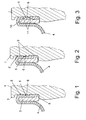
- the rolling piston 1 has a clamping region 2, in which a hose roll 4 is clamped by means of a clamping ring 3 non-positively and positively and pressure-tight.
- a radial circumferential bead 7 and below a radial circumferential shoulder 8 can be seen, through which the clamping region 2 is axially limited.
- the clamping region 2 is provided with a special clamping contour to improve the clamping properties, wherein the clamping contour is substantially characterized by a circumferential, trapezoidal elevation 5, which is arranged approximately in the middle of the clamping region 2.
- the elevation 5, which could also be arcuate or semicircular in the axial direction of the component 1, has approximately in the middle of its trapezoidal plateau a circumferential, grooved or groove-shaped recess 6, which in depth to about the bottom of the trapezoidal Survey 5 is enough.
- the material of Schlauchrollbalgs 4 in this groove or groove-shaped depression 6 pushes.
- the recess 6 has an approximately rectangular or square cross-section. But it could also be other cross sections, for example, semi-circular or triangular. Overall, such a structurally simple, but highly effective clamping contour is generated.
- Fig. 2 It can be seen that the clamping contour is supplemented by a plurality of additional, circumferential and radially tapered elevations 9, which are arranged axially on both sides of the trapezoidal elevation 5. This results in each case a sawtooth contour. Any variation in the number and arrangement of the elevations 9 is conceivable.
- FIG. 3 shows a clamping ring 10 according to the invention, which is provided radially inwardly with two arcuate elevations 11. It can be seen that the elevations 11 axially spaced from each other and are arranged so that they surround the trapezoidal elevation 5 of the rolling piston 1 on both sides in the clamping state or wrap around.
- the shape of the elevations 11 can be varied as needed. It is possible, for example, to make these also trapezoidal.
- An inventively designed clamping contour for a druckbeetzschlagbares component or seal assembly met with simple and inexpensive to manufacture structure in a specific automotive application according to performed tests all requirements for gas and / or liquid tightness in a temperature cycling test according to predetermined test criteria.
Landscapes
- Engineering & Computer Science (AREA)
- General Engineering & Computer Science (AREA)
- Mechanical Engineering (AREA)
- Clamps And Clips (AREA)
Abstract
Description
- Die Erfindung betrifft eine Klemmkontur für ein druckbeaufschlagbares Bauteil, beispielsweise einen Abrollkolben oder eine Anschlussplatte einer Schlauchrollbalg-Luftfeder, wobei das druckbeaufschlagbare Bauteil einen Klemmbereich aufweist, in dem es mittels geeigneter Spannmittel mit einem schlauchförmigen Bauteil, beispielsweise einem Schlauchrollbalg einer Schlauchrollbalg-Luftfeder, verklemmbar ist, und wobei im Klemmbereich wenigstens eine umlaufende Erhebung zur Verbesserung der Klemmung vorgesehen ist.
- Es gibt viele Anwendungsfälle, in denen druckbeaufschlagte Bauteile miteinander zuverlässig und druckdicht verbunden werden müssen, damit eine einwandfreie Funktion des Bauteileverbundes gewährleistet ist. Möglich ist beispielsweise der Anschluss von Schläuchen aus elastomerem Werkstoff an Verbindungsteile bzw. Stutzen in Systemen, welche unter Druck stehende Fluide, wie Wasser, Luft oder Öl, in sich führen. Ein anderer denkbarer Anwendungsfall sind beispielsweise sogenannte Schlauchrollbalg-Luftfedern, welche als Federungsmittel in Kraftfahrzeugen häufig eingesetzt werden. Hierbei wird in der Regel ein aus einem Endlosschlauch abgeschnittener, wulstloser Schlauchrollbalg aus elastomerem Werkstoff mit seinen Enden an Befestigungsteilen dicht angebracht bzw. verklemmt. Üblicherweise erfolgt die Verklemmung mit speziell dafür ausgebildeten Spannmitteln, nämlich geschlossenen metallischen Spannringen, welche durch plastisches, radiales Verformen auf die Wandung des Schlauchrollbalges fest aufgepresst werden. Im Betriebszustand werden der Schlauchrollbalg, mithin auch die Befestigungsteile, mit Druckluft beaufschlagt, wodurch unter dynamischer Belastung eine federnde Relativbewegung zwischen den Befestigungsteilen möglich ist. Das im Betriebszustand oben befindliche Befestigungsteil wird im Allgemeinen als Anschlussplatte und das unten befindliche Befestigungsteil als Abrollkolben bezeichnet, da dieses kolbenartig ausgebildet ist und sich der Schlauchrollbalg bei der federnden Relativbewegung zwischen Anschlussplatte und Abrollkolben auf der Umfangsfläche des Abrollkolbens abrollt.
- Es versteht sich eigentlich von selbst, dass eine nachlassende oder gar fehlerhafte Klemmverbindung zwischen den Bauteilen zu einer spürbaren Verschlechterung oder gar zu einem gänzlichen Versagen des Bauteilverbundes führen kann. Man ist daher ständig bestrebt, die Klemmverbindungen zwischen den druckbeaufschlagten Bauteilen zu verbessern.
- Aus der
DE 103 54 574 B3 ist eine gattungsgemäße Klemmkontur für den Abrollkolben bzw. die Anschlussplatte einer Schlauchrollbalg-Luftfeder bekannt. Im Klemmbereich für den Schlauchrollbalg ist die Klemmkontur dabei durch umlaufende, trapezförmige Erhebungen gebildet. Die trapezförmigen Erhebungen sollen zu einer deutlichen Verbesserung der Dichtheit führen, ohne dass die Gefahr einer Beschädigung der Balgwandung besteht. - Auch die
EP 1 355 079 zeigt eine gattungsgemäße Klemmkontur für eine Schlauchrollbalg-Luftfeder, die durch eine umlaufende, trapezförmige Erhebung gekennzeichnet ist. - In der gattungsbildenden
EP 0 151 696 A1 wird eine Schlauchrollbalg-Luftfeder mit einer sägezahnförmigen Klemmkontur beschrieben, wobei beim Verpressen des Schlauchrollbalges auf dem Abrollkolben die sägezahnförmigen, scharfkantigen Erhebungen in die Balgwandung eindringen, wodurch die kraftschlüssige Verbindung durch einen Formschluss ergänzt und verbessert werden soll. Ein ähnliches Prinzip ist auch aus derDE 10 2004 056 517 A1 bekannt. - Schließlich offenbart die
EP 0 379 667 A1 einen im Längsschnitt speziell ausgebildeten Spannring, der in der Mitte seines Profils mit einer halbkreisförmigen Ausnehmung versehen ist, die mit einer umlaufenden, nasenförmigen Erhebung der dort gezeigten Klemmkontur zusammenwirkt. - Der Erfindung liegt die Aufgabe zugrunde, eine Klemmkontur für ein druckbeaufschlagtes Bauteil, beispielsweise einen Abrollkolben oder eine Anschlussplatte einer Schlauchrollbalg-Luftfeder, bereitzustellen, welche eine zuverlässige, druckdichte Verklemmung der beteiligten Bauteile ermöglicht und welche eine Gefahr von Beschädigungen des schlauchförmigen Teils verringert. Weiterhin soll ein verbessertes Spannmittel für die Verklemmung bereitgestellt werden.
- Der Erfindung liegt die Erkenntnis zugrunde, dass durch die Klemmkontur sowie durch die Wahl geeigneter Spannmittel die Dichtigkeit und der Halt einer Klemmverbindung entscheidend beeinflusst werden kann.
- Gemäß den Merkmalen des Anspruchs 1 geht die Erfindung daher aus von Klemmkontur für ein druckbeaufschlagbares Bauteil, beispielsweise einen Abrollkolben oder eine Anschlussplatte einer Schlauchrollbalg-Luftfeder, wobei das druckbeaufschlagbare Bauteil einen Klemmbereich aufweist, in dem es mittels geeigneter Spannmittel mit einem schlauchförmigen Bauteil, beispielsweise einem Schlauchrollbalg einer Schlauchrollbalg-Luftfeder, verklemmbar ist, und wobei im Klemmbereich wenigstens eine umlaufende Erhebung zur Verbesserung der Klemmung vorgesehen ist. Zudem ist erfindungsgemäß vorgesehen, dass die umlaufende Erhebung mit einer umlaufenden, rillen- oder nutförmigen Vertiefung versehen ist.
- Durch diesen konstruktiven Aufbau wird erreicht, dass bei der Verklemmung das Material des schlauchförmigen Bauteils in die rillen- oder nutförmige Vertiefung gedrückt wird. Somit wird auf relativ einfache Weise ein Kraft- und Formschluss erzielt sowie die Gefahr von Beschädigungen des schlauchförmigen Bauteils verringert.
- Die Unteransprüche beschreiben bevorzugte Weiterbildungen oder Ausgestaltungen der Erfindung.
- So ist gemäß einer ersten bevorzugten Weiterbildung der Erfindung vorgesehen, dass die Erhebung trapezförmig ausgebildet ist. Durch diese Ausgestaltung ergibt sich trotz einer vergrößerten Verpressung des schlauchförmigen Bauteils in diesem Bereich eine relativ gleichmäßige Verteilung der Flächenpressung. Die Gefahr, das schlauchförmige Bauteil durch eine Überhöhung der Flächenpressung zu beschädigen ist also relativ gering. Alternativ dazu kann die Erhebung zweckmäßigerweise aber auch, in axialer Richtung, bogenförmig ausgebildet sein.
- Eine weitere vorteilhafte Weiterbildung der Erfindung sieht vor, dass im Klemmbereich wenigstens eine zusätzliche, umlaufende und radial spitz zulaufende Erhebung vorgesehen ist, welches zu einer Verbesserung des Formschlusses führt. Wenn in weiterer vorteilhafter Ausgestaltung der Erfindung mehrere zusätzliche Erhebungen vorgesehen sind, derart, dass sich eine sägezahnförmige Kontur ergibt, so lässt sich ein noch besserer Formschluss erzielen. Diese sägezahnförmige Kontur ist bevorzugt axial beidseitig der umlaufenden trapezförmigen Erhebung an der radialen Außenseite des Bauteils ausgebildet.
- Zur Lösung der anfangs gestellten Aufgabe ist ebenfalls ein Spannmittel zur Verklemmung eines schlauchförmigen Bauteils, beispielsweise eines Schlauchrollbalg einer Schlauchrollbalg-Luftfeder, in einer Klemmkontur eines druckbeaufschlagbaren Bauteils, beispielsweise ein Abrollkolben oder eine Anschlussplatte einer Schlauchrollbalg-Luftfeder, vorgesehen, wobei das Spannmittel als geschlossener, metallischer Spannring ausgeführt ist. Erfindungsgemäß ist der Spannring dabei radial innenseitig mit wenigstens einer umlaufenden Erhebung versehen.
- Allein durch den Einsatz eines solchen Spannrings kann die Güte der Verklemmung verbessert werden. Insbesondere in Kombination mit der erfindungsgemäßen Klemmkontur mit deren umlaufenden Erhebung sowie der umlaufenden, rillen- oder nutförmigen Vertiefung führt der erfindungsgemäße Spannring zu deutlichen Verbesserungen der Klemmeigenschaften. Die Erhebung am Spannring kann dabei vorteilhafterweise trapez- oder bogenförmig ausgebildet sein. Äußerst zweckmäßig ist dabei, zwei solcher umlaufenden Erhebungen unter axialen Abstand am Spannring vorzusehen, was eine Art Umschlingung der erfindungsgemäßen Klemmkontur des druckbeaufschlagbaren Bauteils durch die Innenkontur des Spannrings ermöglicht.
- Es ist vorteilhaft und daher zu empfehlen, den Abrollkolben und/oder die Anschlussplatte einer Schlauchrollbalg-Luftfeder mit einer erfindungsgemäßen Klemmkontur auszustatten und/oder für die Schlauchrollbalg-Luftfeder zur Verklemmung von Abrollkolben und/oder Anschlussplatte wenigstens ein erfindungsgemäßes Spannmittel vorzusehen.
- Die Erfindung wird im Folgenden anhand der beiliegenden Zeichnung an bevorzugten Ausführungsbeispielen näher erläutert. Darin zeigt
- Fig. 1
- eine Darstellung der Klemmkontur im Längsschnitt gemäß einer ersten Ausführungsform im Montagezustand,
- Fig. 2
- eine Darstellung der Klemmkontur im Längsschnitt gemäß einer zweiten Ausführungsform im Montagezustand, und
- Fig. 3
- eine beispielhafte Darstellung eines erfindungsgemäßen Spannmittels im Längsschnitt im Montagezustand.
- Zunächst wird auf
Fig.1 Bezug genommen. In dieser ist der obere Teil eines Abrollkolbens 1 einer nicht näher dargestellten Schlauchrollbalg-Luftfeder zu sehen. Der Abrollkolben 1 weist einen Klemmbereich 2 auf, in dem ein Schlauchrollbalg 4 mittels eines Spannrings 3 kraft- und formschlüssig sowie druckdicht verklemmt ist. Ferner ist oben am Abrollkolben 1 ein radialer umlaufender Wulst 7 und unten ein radialer umlaufender Absatz 8 ersichtlich, durch die der Klemmbereich 2 axial begrenzt ist. - Der Klemmbereich 2 ist mit einer speziellen Klemmkontur zur Verbesserung der Klemmeigenschaften versehen, wobei die Klemmkontur im wesentlichen durch eine umlaufende, trapezförmige Erhebung 5 geprägt ist, welche in etwa in der Mitte des Klemmbereichs 2 angeordnet ist. Die Erhebung 5, die in axialer Richtung des Bauteils 1 auch bogen- oder halbkreisförmig ausgeführt sein könnte, weist in etwa in der Mitte ihres Trapezplateaus eine umlaufende, rillen- oder nutförmige Vertiefung 6 auf, welche in ihrer Tiefe in etwa bis zum Grund der trapezförmigen Erhebung 5 reicht. Es ist zu erkennen, dass sich im gezeigten Klemm- bzw. Montagezustand das Material des Schlauchrollbalgs 4 in diese rillen- oder nutförmige Vertiefung 6 hinein drückt. Im Beispiel weist die Vertiefung 6 einen in etwa rechteckigen bzw. quadratischen Querschnitt auf. Sie könnte aber auch andere Querschnitte, beispielsweise halbreis- oder dreieckförmig ausgebildet sein. Insgesamt ist so eine konstruktiv einfache, aber hochwirksame Klemmkontur erzeugt.
- Nun Bezug nehmend auf
Fig. 2 ist zu erkennen, dass die Klemmkontur durch mehrere zusätzliche, umlaufende und radial spitz zulaufende Erhebungen 9 ergänzt ist, die axial beidseitig der trapezförmigen Erhebung 5 angeordnet sind. Dadurch ergibt sich jeweils eine sägezahnförmige Kontur. Es ist eine beliebige Variation in der Anzahl und Anordnung der Erhebungen 9 denkbar. -
Fig. 3 zeigt schließlich einen erfindungsgemäßen Spannring 10, welcher radial innenseitig mit zwei bogenförmigen Erhebungen 11 versehen ist. Es ist zu erkennen, dass die Erhebungen 11 axial derart zueinander beabstandet und angeordnet sind, dass sie im Klemmzustand die trapezförmige Erhebung 5 des Abrollkolbens 1 beidseitig umgeben bzw. umschlingen. Auch die Form der Erhebungen 11 kann nach Bedarf variiert werden. Möglich ist beispielsweise, diese auch trapezförmig auszubilden. - Eine erfindungsgemäß ausgebildete Klemmkontur für ein druckbeaufschlagbares Bauteil bzw. Dichtungsanordnung erfüllte bei einfachem und kostengünstig herzustellendem Aufbau in einem konkreten kraftfahrzeugtechnischen Anwendungsfall entsprechend durchgeführter Untersuchungen alle Anforderungen hinsichtlich der Gas- und/oder Flüssigkeitsdichtigkeit in einem Temperaturwechseltest nach vorgegebenen Prüfkriterien.
-
- 1
- Abrollkolben einer Schlauchrollbalg-Luftfeder
- 2
- Klemmbereich des Abrollkolbens
- 3
- Spannring
- 4
- Schlauchrollbalg
- 5
- Trapezförmige Erhebung
- 6
- Rillen- bzw. nutförmige Vertiefung
- 7
- Umlaufende Wulst
- 8
- Umlaufender Absatz
- 9
- Umlaufende und radial spitz zulaufende Erhebungen
- 10
- Spannring
- 11
- Radial innenseitige, umlaufende Erhebungen des Spannrings
Claims (9)
- Klemmkontur für ein druckbeaufschlagbares Bauteil (1), beispielsweise Abrollkolben oder Anschlussplatte einer Schlauchrollbalg-Luftfeder, wobei das druckbeaufschlagbare Bauteil (1) einen Klemmbereich (2) aufweist, in dem es mittels geeigneter Spannmittel (3) mit einem schlauchförmigen Bauteil (4), beispielsweise einem Schlauchrollbalg einer Schlauchrollbalg-Luftfeder, verklemmbar ist, und wobei im Klemmbereich (2) wenigstens eine umlaufende Erhebung (5) zur Verbesserung der Klemmung vorgesehen ist, dadurch gekennzeichnet, dass die umlaufende Erhebung (5) mit einer umlaufenden, rillen- oder nutförmigen Vertiefung (6) versehen ist.
- Klemmkontur nach Anspruch 1, dadurch gekennzeichnet, dass die Erhebung (5) trapezförmig ausgebildet ist.
- Klemmkontur nach Anspruch 1, dadurch gekennzeichnet, dass die Erhebung (5) bogenförmig ausgebildet ist.
- Klemmkontur nach einem der Ansprüche 1 bis 3, dadurch gekennzeichnet, dass im Klemmbereich (2) wenigstens eine zusätzliche, umlaufende und radial spitz ausgebildete Erhebung (9) vorgesehen ist.
- Klemmkontur nach Anspruch 4, dadurch gekennzeichnet, dass mehrere zusätzliche umlaufende und radial spitz ausgebildete Erhebungen (9) vorgesehen sind, derart, dass sich eine sägezahnförmige Kontur ergibt.
- Spannmittel (10) zur Verklemmung eines schlauchförmigen Bauteils (4), beispielsweise Schlauchrollbalg einer Schlauchrollbalg-Luftfeder, in einer Klemmkontur eines druckbeaufschlagbaren Bauteils (1), insbesondere nach den Ansprüchen 1 bis 5, wobei das Spannmittel (10) als geschlossener, metallischer Spannring ausgeführt ist, dadurch gekennzeichnet, dass der Spannring (10) radial innenseitig mit wenigstens einer umlaufenden Erhebung (11) versehen ist.
- Spannmittel (10) nach Anspruch 6, dadurch gekennzeichnet, dass die Erhebung (11) trapez- oder bogenförmig ausgebildet ist.
- Spannmittel (10) nach einem der Ansprüche 6 oder 7, dadurch gekennzeichnet, dass zwei umlaufende Erhebungen (11) vorgesehen sind.
- Schlauchrollbalg-Luftfeder mit wenigstens einem druckbeaufschlagten Bauteil (1), nämlich Abrollkolben oder Anschlussplatte, wobei das Bauteil (1) eine Klemmkontur nach wenigstens einem der Ansprüche 1 bis 5 aufweist, und/oder mit wenigstens einem Spannmittel (10) nach wenigstens einem der Ansprüche 6 bis 8.
Applications Claiming Priority (1)
| Application Number | Priority Date | Filing Date | Title |
|---|---|---|---|
| DE200710055077 DE102007055077A1 (de) | 2007-11-16 | 2007-11-16 | Klemmkontur für ein druckbeaufschlagbares Bauteil und Spannmittel dafür |
Publications (3)
| Publication Number | Publication Date |
|---|---|
| EP2060832A2 true EP2060832A2 (de) | 2009-05-20 |
| EP2060832A3 EP2060832A3 (de) | 2011-11-30 |
| EP2060832B1 EP2060832B1 (de) | 2015-09-16 |
Family
ID=40386158
Family Applications (1)
| Application Number | Title | Priority Date | Filing Date |
|---|---|---|---|
| EP08165958.3A Revoked EP2060832B1 (de) | 2007-11-16 | 2008-10-07 | Klemmkontur für ein druckbeaufschlagbares Bauteil und Spannmittel dafür |
Country Status (2)
| Country | Link |
|---|---|
| EP (1) | EP2060832B1 (de) |
| DE (1) | DE102007055077A1 (de) |
Cited By (1)
| Publication number | Priority date | Publication date | Assignee | Title |
|---|---|---|---|---|
| WO2014190123A1 (en) * | 2013-05-22 | 2014-11-27 | Firestone Industrial Products Company, Llc | End member and gas spring assembly including same |
Families Citing this family (2)
| Publication number | Priority date | Publication date | Assignee | Title |
|---|---|---|---|---|
| DE102017209199A1 (de) | 2017-05-31 | 2018-12-06 | Contitech Luftfedersysteme Gmbh | Luftfeder |
| DE102017209201A1 (de) | 2017-05-31 | 2018-12-06 | Contitech Luftfedersysteme Gmbh | Luftfeder |
Citations (5)
| Publication number | Priority date | Publication date | Assignee | Title |
|---|---|---|---|---|
| EP0151696A1 (de) | 1983-12-21 | 1985-08-21 | Continental Aktiengesellschaft | Luftfederung insbesondere für Strassenfahrzeuge |
| EP0379667A1 (de) | 1988-12-29 | 1990-08-01 | Bridgestone/Firestone, Inc. | Befestigungsring für eine pneumatische Feder |
| EP1355079A1 (de) | 2002-04-16 | 2003-10-22 | ContiTech Luftfedersysteme GmbH | Schauchrollbalg-Luftfeder |
| DE10354574B3 (de) | 2003-11-21 | 2005-01-27 | Contitech Luftfedersysteme Gmbh | Luftfeder mit einem wulstlosen Schlauchrollbalg |
| DE102004056517A1 (de) | 2004-11-24 | 2006-06-01 | Contitech Luftfedersysteme Gmbh | Tiefbettklemmkontur für Schlauchrollbalg-Luftfedern |
Family Cites Families (5)
| Publication number | Priority date | Publication date | Assignee | Title |
|---|---|---|---|---|
| US5374037A (en) * | 1993-09-20 | 1994-12-20 | Bridgestone/Firestone, Inc. | Clamp ring assembly for air spring |
| DE10050777B4 (de) * | 2000-10-13 | 2004-09-30 | Continental Aktiengesellschaft | Luftfeder und Verfahren zur Herstellung einer Luftfeder |
| US6619635B1 (en) | 2002-04-08 | 2003-09-16 | Bfs Diversified Products, Llc | Air spring clamping assembly |
| US6719279B1 (en) * | 2002-08-21 | 2004-04-13 | Bfs Diversified Products, Llc | Air spring sleeve |
| DE102005017995A1 (de) * | 2005-04-19 | 2006-11-02 | Carl Freudenberg Kg | Befestigung eines Endabschnitts eines Rollbalgs an einem Anschlussteil |
-
2007
- 2007-11-16 DE DE200710055077 patent/DE102007055077A1/de not_active Ceased
-
2008
- 2008-10-07 EP EP08165958.3A patent/EP2060832B1/de not_active Revoked
Patent Citations (5)
| Publication number | Priority date | Publication date | Assignee | Title |
|---|---|---|---|---|
| EP0151696A1 (de) | 1983-12-21 | 1985-08-21 | Continental Aktiengesellschaft | Luftfederung insbesondere für Strassenfahrzeuge |
| EP0379667A1 (de) | 1988-12-29 | 1990-08-01 | Bridgestone/Firestone, Inc. | Befestigungsring für eine pneumatische Feder |
| EP1355079A1 (de) | 2002-04-16 | 2003-10-22 | ContiTech Luftfedersysteme GmbH | Schauchrollbalg-Luftfeder |
| DE10354574B3 (de) | 2003-11-21 | 2005-01-27 | Contitech Luftfedersysteme Gmbh | Luftfeder mit einem wulstlosen Schlauchrollbalg |
| DE102004056517A1 (de) | 2004-11-24 | 2006-06-01 | Contitech Luftfedersysteme Gmbh | Tiefbettklemmkontur für Schlauchrollbalg-Luftfedern |
Cited By (3)
| Publication number | Priority date | Publication date | Assignee | Title |
|---|---|---|---|---|
| WO2014190123A1 (en) * | 2013-05-22 | 2014-11-27 | Firestone Industrial Products Company, Llc | End member and gas spring assembly including same |
| US9951837B2 (en) | 2013-05-22 | 2018-04-24 | Firestone Industrial Products Company, Llc | End member and gas spring assembly including same |
| US10962078B2 (en) | 2013-05-22 | 2021-03-30 | Firestone Industrial Products Company, Llc | End member and gas spring assembly including same |
Also Published As
| Publication number | Publication date |
|---|---|
| EP2060832A3 (de) | 2011-11-30 |
| EP2060832B1 (de) | 2015-09-16 |
| DE102007055077A1 (de) | 2009-05-20 |
Similar Documents
| Publication | Publication Date | Title |
|---|---|---|
| DE102015007743B4 (de) | Schublager und druckluftbeaufschlagter Stoßdämpfer | |
| DE3721558C2 (de) | Endverschluß für einen Fluidzylinder | |
| DE10131075A1 (de) | Aggregatelager in Buchsenform | |
| EP1031756B1 (de) | Befestigung eines Luftfeder-Rollbalges an einem Stützteil | |
| DE102018131097A1 (de) | Vorrichtung zur Sicherung eines Druckausgleichsventils in einem Getriebebauteil, Druckausgleichsventil und Vorrichtung zur Regelung von Drücken eines Strömungsmittels in einem Fahrzeuggetriebe | |
| EP2847487A1 (de) | Luftfeder und verfahren zum umschlagen eines luftfederbalges einer luftfeder | |
| EP3299682B1 (de) | Dichtring und dessen verwendung | |
| EP3872373B1 (de) | Dichtring und dessen verwendung | |
| DE19917006A1 (de) | Zylinder für eine hydraulische Anlage | |
| EP2060832B1 (de) | Klemmkontur für ein druckbeaufschlagbares Bauteil und Spannmittel dafür | |
| DE2159487B2 (de) | Zahnstangen-Hydrolenkung, insbesondere für Kraftfahrzeuge | |
| EP2307751B1 (de) | An einem führungsholm einer scheibenbremse angeordneter faltenbalg | |
| EP1657467B1 (de) | Verfahren zur Montage einer Luftfeder | |
| DE102017110716B3 (de) | Kolben-Zylinder-Anordnung für ein Kupplungs- oder Bremssystem und Kupplung mit einer Kolben-Zylinder-Anordnung | |
| DE68902855T2 (de) | Passiver schwingungsdaempfer, insbesondere fuer die verbindung eines motors an einem fahrzeug. | |
| EP0412997A1 (de) | Dichtungsanordnung. | |
| EP1375958B1 (de) | Anschlagring für ein Kolben-Zylinderaggregat | |
| DE4317483A1 (de) | Kolben, insbesondere für den Servozylinder einer Hilfskraftlenkanlage | |
| DE102020210763A1 (de) | Filtervorrichtung zur Dämpfung von Vibrationen in einer Leitung eines hydraulischen Betätigungssystems zum Ausrücken einer Kupplung | |
| DE102021200486A1 (de) | Presswerkzeug zum Befestigen eines Zuganschlagrings an einer Kolbenstange eines Kraftfahrzeugschwingungsdämpfers | |
| EP3155288B1 (de) | Trennkolben sowie einrohrdämpfer | |
| EP4317749B1 (de) | Dichtungsanordnung und wasseraufbereitungsgerät, das die dichtungsanordnung umfasst | |
| DE102017218463A1 (de) | Kolbenventilanordnung für einen Kraftfahrzeugschwingungsdämpfer | |
| DE102019209758B3 (de) | Dämpfventil für einen Schwingungsdämpfer | |
| EP1715221B1 (de) | Befestigung eines Endabschnitts eines Rollbalgs an einem Anschlussteil |
Legal Events
| Date | Code | Title | Description |
|---|---|---|---|
| PUAI | Public reference made under article 153(3) epc to a published international application that has entered the european phase |
Free format text: ORIGINAL CODE: 0009012 |
|
| AK | Designated contracting states |
Kind code of ref document: A2 Designated state(s): AT BE BG CH CY CZ DE DK EE ES FI FR GB GR HR HU IE IS IT LI LT LU LV MC MT NL NO PL PT RO SE SI SK TR |
|
| AX | Request for extension of the european patent |
Extension state: AL BA MK RS |
|
| RAP1 | Party data changed (applicant data changed or rights of an application transferred) |
Owner name: CONTINENTAL TEVES AG & CO. OHG |
|
| PUAL | Search report despatched |
Free format text: ORIGINAL CODE: 0009013 |
|
| AK | Designated contracting states |
Kind code of ref document: A3 Designated state(s): AT BE BG CH CY CZ DE DK EE ES FI FR GB GR HR HU IE IS IT LI LT LU LV MC MT NL NO PL PT RO SE SI SK TR |
|
| AX | Request for extension of the european patent |
Extension state: AL BA MK RS |
|
| RIC1 | Information provided on ipc code assigned before grant |
Ipc: F16J 3/04 20060101AFI20111025BHEP Ipc: F16J 3/06 20060101ALI20111025BHEP Ipc: F16F 9/04 20060101ALI20111025BHEP |
|
| 17P | Request for examination filed |
Effective date: 20120530 |
|
| AKX | Designation fees paid |
Designated state(s): AT BE BG CH CY CZ DE DK EE ES FI FR GB GR HR HU IE IS IT LI LT LU LV MC MT NL NO PL PT RO SE SI SK TR |
|
| 17Q | First examination report despatched |
Effective date: 20131219 |
|
| GRAP | Despatch of communication of intention to grant a patent |
Free format text: ORIGINAL CODE: EPIDOSNIGR1 |
|
| INTG | Intention to grant announced |
Effective date: 20150529 |
|
| INTG | Intention to grant announced |
Effective date: 20150605 |
|
| GRAS | Grant fee paid |
Free format text: ORIGINAL CODE: EPIDOSNIGR3 |
|
| GRAA | (expected) grant |
Free format text: ORIGINAL CODE: 0009210 |
|
| AK | Designated contracting states |
Kind code of ref document: B1 Designated state(s): AT BE BG CH CY CZ DE DK EE ES FI FR GB GR HR HU IE IS IT LI LT LU LV MC MT NL NO PL PT RO SE SI SK TR |
|
| REG | Reference to a national code |
Ref country code: GB Ref legal event code: FG4D Free format text: NOT ENGLISH |
|
| REG | Reference to a national code |
Ref country code: CH Ref legal event code: EP |
|
| REG | Reference to a national code |
Ref country code: IE Ref legal event code: FG4D Free format text: LANGUAGE OF EP DOCUMENT: GERMAN |
|
| REG | Reference to a national code |
Ref country code: AT Ref legal event code: REF Ref document number: 750083 Country of ref document: AT Kind code of ref document: T Effective date: 20151015 |
|
| REG | Reference to a national code |
Ref country code: FR Ref legal event code: PLFP Year of fee payment: 8 |
|
| REG | Reference to a national code |
Ref country code: DE Ref legal event code: R096 Ref document number: 502008013386 Country of ref document: DE |
|
| REG | Reference to a national code |
Ref country code: NL Ref legal event code: MP Effective date: 20150916 |
|
| PG25 | Lapsed in a contracting state [announced via postgrant information from national office to epo] |
Ref country code: NO Free format text: LAPSE BECAUSE OF FAILURE TO SUBMIT A TRANSLATION OF THE DESCRIPTION OR TO PAY THE FEE WITHIN THE PRESCRIBED TIME-LIMIT Effective date: 20151216 Ref country code: GR Free format text: LAPSE BECAUSE OF FAILURE TO SUBMIT A TRANSLATION OF THE DESCRIPTION OR TO PAY THE FEE WITHIN THE PRESCRIBED TIME-LIMIT Effective date: 20151217 Ref country code: LV Free format text: LAPSE BECAUSE OF FAILURE TO SUBMIT A TRANSLATION OF THE DESCRIPTION OR TO PAY THE FEE WITHIN THE PRESCRIBED TIME-LIMIT Effective date: 20150916 Ref country code: FI Free format text: LAPSE BECAUSE OF FAILURE TO SUBMIT A TRANSLATION OF THE DESCRIPTION OR TO PAY THE FEE WITHIN THE PRESCRIBED TIME-LIMIT Effective date: 20150916 Ref country code: LT Free format text: LAPSE BECAUSE OF FAILURE TO SUBMIT A TRANSLATION OF THE DESCRIPTION OR TO PAY THE FEE WITHIN THE PRESCRIBED TIME-LIMIT Effective date: 20150916 |
|
| REG | Reference to a national code |
Ref country code: LT Ref legal event code: MG4D |
|
| PG25 | Lapsed in a contracting state [announced via postgrant information from national office to epo] |
Ref country code: HR Free format text: LAPSE BECAUSE OF FAILURE TO SUBMIT A TRANSLATION OF THE DESCRIPTION OR TO PAY THE FEE WITHIN THE PRESCRIBED TIME-LIMIT Effective date: 20150916 Ref country code: SE Free format text: LAPSE BECAUSE OF FAILURE TO SUBMIT A TRANSLATION OF THE DESCRIPTION OR TO PAY THE FEE WITHIN THE PRESCRIBED TIME-LIMIT Effective date: 20150916 |
|
| PG25 | Lapsed in a contracting state [announced via postgrant information from national office to epo] |
Ref country code: NL Free format text: LAPSE BECAUSE OF FAILURE TO SUBMIT A TRANSLATION OF THE DESCRIPTION OR TO PAY THE FEE WITHIN THE PRESCRIBED TIME-LIMIT Effective date: 20150916 |
|
| PG25 | Lapsed in a contracting state [announced via postgrant information from national office to epo] |
Ref country code: ES Free format text: LAPSE BECAUSE OF FAILURE TO SUBMIT A TRANSLATION OF THE DESCRIPTION OR TO PAY THE FEE WITHIN THE PRESCRIBED TIME-LIMIT Effective date: 20150916 Ref country code: CZ Free format text: LAPSE BECAUSE OF FAILURE TO SUBMIT A TRANSLATION OF THE DESCRIPTION OR TO PAY THE FEE WITHIN THE PRESCRIBED TIME-LIMIT Effective date: 20150916 Ref country code: SK Free format text: LAPSE BECAUSE OF FAILURE TO SUBMIT A TRANSLATION OF THE DESCRIPTION OR TO PAY THE FEE WITHIN THE PRESCRIBED TIME-LIMIT Effective date: 20150916 Ref country code: EE Free format text: LAPSE BECAUSE OF FAILURE TO SUBMIT A TRANSLATION OF THE DESCRIPTION OR TO PAY THE FEE WITHIN THE PRESCRIBED TIME-LIMIT Effective date: 20150916 Ref country code: IT Free format text: LAPSE BECAUSE OF FAILURE TO SUBMIT A TRANSLATION OF THE DESCRIPTION OR TO PAY THE FEE WITHIN THE PRESCRIBED TIME-LIMIT Effective date: 20150916 Ref country code: IS Free format text: LAPSE BECAUSE OF FAILURE TO SUBMIT A TRANSLATION OF THE DESCRIPTION OR TO PAY THE FEE WITHIN THE PRESCRIBED TIME-LIMIT Effective date: 20160116 |
|
| PG25 | Lapsed in a contracting state [announced via postgrant information from national office to epo] |
Ref country code: RO Free format text: LAPSE BECAUSE OF FAILURE TO SUBMIT A TRANSLATION OF THE DESCRIPTION OR TO PAY THE FEE WITHIN THE PRESCRIBED TIME-LIMIT Effective date: 20150916 Ref country code: PL Free format text: LAPSE BECAUSE OF FAILURE TO SUBMIT A TRANSLATION OF THE DESCRIPTION OR TO PAY THE FEE WITHIN THE PRESCRIBED TIME-LIMIT Effective date: 20150916 Ref country code: PT Free format text: LAPSE BECAUSE OF FAILURE TO SUBMIT A TRANSLATION OF THE DESCRIPTION OR TO PAY THE FEE WITHIN THE PRESCRIBED TIME-LIMIT Effective date: 20160118 |
|
| REG | Reference to a national code |
Ref country code: CH Ref legal event code: PL |
|
| REG | Reference to a national code |
Ref country code: DE Ref legal event code: R026 Ref document number: 502008013386 Country of ref document: DE |
|
| PLBI | Opposition filed |
Free format text: ORIGINAL CODE: 0009260 |
|
| PG25 | Lapsed in a contracting state [announced via postgrant information from national office to epo] |
Ref country code: MC Free format text: LAPSE BECAUSE OF FAILURE TO SUBMIT A TRANSLATION OF THE DESCRIPTION OR TO PAY THE FEE WITHIN THE PRESCRIBED TIME-LIMIT Effective date: 20150916 |
|
| 26 | Opposition filed |
Opponent name: DRAVIMA B.V. Effective date: 20160613 |
|
| PLAX | Notice of opposition and request to file observation + time limit sent |
Free format text: ORIGINAL CODE: EPIDOSNOBS2 |
|
| REG | Reference to a national code |
Ref country code: IE Ref legal event code: MM4A |
|
| PG25 | Lapsed in a contracting state [announced via postgrant information from national office to epo] |
Ref country code: CH Free format text: LAPSE BECAUSE OF NON-PAYMENT OF DUE FEES Effective date: 20151031 Ref country code: LI Free format text: LAPSE BECAUSE OF NON-PAYMENT OF DUE FEES Effective date: 20151031 |
|
| GBPC | Gb: european patent ceased through non-payment of renewal fee |
Effective date: 20151216 |
|
| PG25 | Lapsed in a contracting state [announced via postgrant information from national office to epo] |
Ref country code: DK Free format text: LAPSE BECAUSE OF FAILURE TO SUBMIT A TRANSLATION OF THE DESCRIPTION OR TO PAY THE FEE WITHIN THE PRESCRIBED TIME-LIMIT Effective date: 20150916 |
|
| PLBB | Reply of patent proprietor to notice(s) of opposition received |
Free format text: ORIGINAL CODE: EPIDOSNOBS3 |
|
| REG | Reference to a national code |
Ref country code: FR Ref legal event code: PLFP Year of fee payment: 9 |
|
| PG25 | Lapsed in a contracting state [announced via postgrant information from national office to epo] |
Ref country code: GB Free format text: LAPSE BECAUSE OF NON-PAYMENT OF DUE FEES Effective date: 20151216 Ref country code: IE Free format text: LAPSE BECAUSE OF NON-PAYMENT OF DUE FEES Effective date: 20151007 |
|
| PG25 | Lapsed in a contracting state [announced via postgrant information from national office to epo] |
Ref country code: SI Free format text: LAPSE BECAUSE OF FAILURE TO SUBMIT A TRANSLATION OF THE DESCRIPTION OR TO PAY THE FEE WITHIN THE PRESCRIBED TIME-LIMIT Effective date: 20150916 |
|
| RDAF | Communication despatched that patent is revoked |
Free format text: ORIGINAL CODE: EPIDOSNREV1 |
|
| STAA | Information on the status of an ep patent application or granted ep patent |
Free format text: STATUS: THE PATENT HAS BEEN GRANTED |
|
| REG | Reference to a national code |
Ref country code: AT Ref legal event code: MM01 Ref document number: 750083 Country of ref document: AT Kind code of ref document: T Effective date: 20151007 |
|
| REG | Reference to a national code |
Ref country code: DE Ref legal event code: R064 Ref document number: 502008013386 Country of ref document: DE Ref country code: DE Ref legal event code: R103 Ref document number: 502008013386 Country of ref document: DE |
|
| PGFP | Annual fee paid to national office [announced via postgrant information from national office to epo] |
Ref country code: FR Payment date: 20161020 Year of fee payment: 9 Ref country code: DE Payment date: 20161031 Year of fee payment: 9 |
|
| PG25 | Lapsed in a contracting state [announced via postgrant information from national office to epo] |
Ref country code: AT Free format text: LAPSE BECAUSE OF NON-PAYMENT OF DUE FEES Effective date: 20151007 |
|
| RDAG | Patent revoked |
Free format text: ORIGINAL CODE: 0009271 |
|
| 27W | Patent revoked |
Effective date: 20161216 |
|
| PG25 | Lapsed in a contracting state [announced via postgrant information from national office to epo] |
Ref country code: HU Free format text: LAPSE BECAUSE OF FAILURE TO SUBMIT A TRANSLATION OF THE DESCRIPTION OR TO PAY THE FEE WITHIN THE PRESCRIBED TIME-LIMIT; INVALID AB INITIO Effective date: 20081007 |
|
| REG | Reference to a national code |
Ref country code: AT Ref legal event code: MA03 Ref document number: 750083 Country of ref document: AT Kind code of ref document: T Effective date: 20161216 |
|
| PG25 | Lapsed in a contracting state [announced via postgrant information from national office to epo] |
Ref country code: MT Free format text: LAPSE BECAUSE OF FAILURE TO SUBMIT A TRANSLATION OF THE DESCRIPTION OR TO PAY THE FEE WITHIN THE PRESCRIBED TIME-LIMIT Effective date: 20150916 |
|
| STAA | Information on the status of an ep patent application or granted ep patent |
Free format text: STATUS: PATENT REVOKED |
|
| PG25 | Lapsed in a contracting state [announced via postgrant information from national office to epo] |
Ref country code: BG Free format text: LAPSE BECAUSE OF FAILURE TO SUBMIT A TRANSLATION OF THE DESCRIPTION OR TO PAY THE FEE WITHIN THE PRESCRIBED TIME-LIMIT Effective date: 20150916 |
|
| PG25 | Lapsed in a contracting state [announced via postgrant information from national office to epo] |
Ref country code: CY Free format text: LAPSE BECAUSE OF FAILURE TO SUBMIT A TRANSLATION OF THE DESCRIPTION OR TO PAY THE FEE WITHIN THE PRESCRIBED TIME-LIMIT Effective date: 20150916 |
|
| PG25 | Lapsed in a contracting state [announced via postgrant information from national office to epo] |
Ref country code: TR Free format text: LAPSE BECAUSE OF FAILURE TO SUBMIT A TRANSLATION OF THE DESCRIPTION OR TO PAY THE FEE WITHIN THE PRESCRIBED TIME-LIMIT Effective date: 20150916 |