EP1355105A2 - Réservoir sous pression - Google Patents
Réservoir sous pression Download PDFInfo
- Publication number
- EP1355105A2 EP1355105A2 EP03008402A EP03008402A EP1355105A2 EP 1355105 A2 EP1355105 A2 EP 1355105A2 EP 03008402 A EP03008402 A EP 03008402A EP 03008402 A EP03008402 A EP 03008402A EP 1355105 A2 EP1355105 A2 EP 1355105A2
- Authority
- EP
- European Patent Office
- Prior art keywords
- pressure tank
- tank according
- cell
- cells
- adjacent
- Prior art date
- Legal status (The legal status is an assumption and is not a legal conclusion. Google has not performed a legal analysis and makes no representation as to the accuracy of the status listed.)
- Granted
Links
Images


Classifications
-
- F—MECHANICAL ENGINEERING; LIGHTING; HEATING; WEAPONS; BLASTING
- F17—STORING OR DISTRIBUTING GASES OR LIQUIDS
- F17C—VESSELS FOR CONTAINING OR STORING COMPRESSED, LIQUEFIED OR SOLIDIFIED GASES; FIXED-CAPACITY GAS-HOLDERS; FILLING VESSELS WITH, OR DISCHARGING FROM VESSELS, COMPRESSED, LIQUEFIED, OR SOLIDIFIED GASES
- F17C13/00—Details of vessels or of the filling or discharging of vessels
- F17C13/08—Mounting arrangements for vessels
- F17C13/083—Mounting arrangements for vessels for medium-sized mobile storage vessels, e.g. tank vehicles or railway tank vehicles
-
- F—MECHANICAL ENGINEERING; LIGHTING; HEATING; WEAPONS; BLASTING
- F17—STORING OR DISTRIBUTING GASES OR LIQUIDS
- F17C—VESSELS FOR CONTAINING OR STORING COMPRESSED, LIQUEFIED OR SOLIDIFIED GASES; FIXED-CAPACITY GAS-HOLDERS; FILLING VESSELS WITH, OR DISCHARGING FROM VESSELS, COMPRESSED, LIQUEFIED, OR SOLIDIFIED GASES
- F17C1/00—Pressure vessels, e.g. gas cylinder, gas tank, replaceable cartridge
- F17C1/14—Pressure vessels, e.g. gas cylinder, gas tank, replaceable cartridge constructed of aluminium; constructed of non-magnetic steel
-
- F—MECHANICAL ENGINEERING; LIGHTING; HEATING; WEAPONS; BLASTING
- F17—STORING OR DISTRIBUTING GASES OR LIQUIDS
- F17C—VESSELS FOR CONTAINING OR STORING COMPRESSED, LIQUEFIED OR SOLIDIFIED GASES; FIXED-CAPACITY GAS-HOLDERS; FILLING VESSELS WITH, OR DISCHARGING FROM VESSELS, COMPRESSED, LIQUEFIED, OR SOLIDIFIED GASES
- F17C2201/00—Vessel construction, in particular geometry, arrangement or size
- F17C2201/01—Shape
- F17C2201/0147—Shape complex
- F17C2201/0152—Lobes
-
- F—MECHANICAL ENGINEERING; LIGHTING; HEATING; WEAPONS; BLASTING
- F17—STORING OR DISTRIBUTING GASES OR LIQUIDS
- F17C—VESSELS FOR CONTAINING OR STORING COMPRESSED, LIQUEFIED OR SOLIDIFIED GASES; FIXED-CAPACITY GAS-HOLDERS; FILLING VESSELS WITH, OR DISCHARGING FROM VESSELS, COMPRESSED, LIQUEFIED, OR SOLIDIFIED GASES
- F17C2201/00—Vessel construction, in particular geometry, arrangement or size
- F17C2201/01—Shape
- F17C2201/0147—Shape complex
- F17C2201/0166—Shape complex divided in several chambers
-
- F—MECHANICAL ENGINEERING; LIGHTING; HEATING; WEAPONS; BLASTING
- F17—STORING OR DISTRIBUTING GASES OR LIQUIDS
- F17C—VESSELS FOR CONTAINING OR STORING COMPRESSED, LIQUEFIED OR SOLIDIFIED GASES; FIXED-CAPACITY GAS-HOLDERS; FILLING VESSELS WITH, OR DISCHARGING FROM VESSELS, COMPRESSED, LIQUEFIED, OR SOLIDIFIED GASES
- F17C2201/00—Vessel construction, in particular geometry, arrangement or size
- F17C2201/01—Shape
- F17C2201/0147—Shape complex
- F17C2201/0171—Shape complex comprising a communication hole between chambers
-
- F—MECHANICAL ENGINEERING; LIGHTING; HEATING; WEAPONS; BLASTING
- F17—STORING OR DISTRIBUTING GASES OR LIQUIDS
- F17C—VESSELS FOR CONTAINING OR STORING COMPRESSED, LIQUEFIED OR SOLIDIFIED GASES; FIXED-CAPACITY GAS-HOLDERS; FILLING VESSELS WITH, OR DISCHARGING FROM VESSELS, COMPRESSED, LIQUEFIED, OR SOLIDIFIED GASES
- F17C2201/00—Vessel construction, in particular geometry, arrangement or size
- F17C2201/03—Orientation
- F17C2201/035—Orientation with substantially horizontal main axis
-
- F—MECHANICAL ENGINEERING; LIGHTING; HEATING; WEAPONS; BLASTING
- F17—STORING OR DISTRIBUTING GASES OR LIQUIDS
- F17C—VESSELS FOR CONTAINING OR STORING COMPRESSED, LIQUEFIED OR SOLIDIFIED GASES; FIXED-CAPACITY GAS-HOLDERS; FILLING VESSELS WITH, OR DISCHARGING FROM VESSELS, COMPRESSED, LIQUEFIED, OR SOLIDIFIED GASES
- F17C2201/00—Vessel construction, in particular geometry, arrangement or size
- F17C2201/05—Size
- F17C2201/056—Small (<1 m3)
-
- F—MECHANICAL ENGINEERING; LIGHTING; HEATING; WEAPONS; BLASTING
- F17—STORING OR DISTRIBUTING GASES OR LIQUIDS
- F17C—VESSELS FOR CONTAINING OR STORING COMPRESSED, LIQUEFIED OR SOLIDIFIED GASES; FIXED-CAPACITY GAS-HOLDERS; FILLING VESSELS WITH, OR DISCHARGING FROM VESSELS, COMPRESSED, LIQUEFIED, OR SOLIDIFIED GASES
- F17C2203/00—Vessel construction, in particular walls or details thereof
- F17C2203/01—Reinforcing or suspension means
- F17C2203/011—Reinforcing means
- F17C2203/012—Reinforcing means on or in the wall, e.g. ribs
-
- F—MECHANICAL ENGINEERING; LIGHTING; HEATING; WEAPONS; BLASTING
- F17—STORING OR DISTRIBUTING GASES OR LIQUIDS
- F17C—VESSELS FOR CONTAINING OR STORING COMPRESSED, LIQUEFIED OR SOLIDIFIED GASES; FIXED-CAPACITY GAS-HOLDERS; FILLING VESSELS WITH, OR DISCHARGING FROM VESSELS, COMPRESSED, LIQUEFIED, OR SOLIDIFIED GASES
- F17C2203/00—Vessel construction, in particular walls or details thereof
- F17C2203/06—Materials for walls or layers thereof; Properties or structures of walls or their materials
- F17C2203/0602—Wall structures; Special features thereof
- F17C2203/0607—Coatings
-
- F—MECHANICAL ENGINEERING; LIGHTING; HEATING; WEAPONS; BLASTING
- F17—STORING OR DISTRIBUTING GASES OR LIQUIDS
- F17C—VESSELS FOR CONTAINING OR STORING COMPRESSED, LIQUEFIED OR SOLIDIFIED GASES; FIXED-CAPACITY GAS-HOLDERS; FILLING VESSELS WITH, OR DISCHARGING FROM VESSELS, COMPRESSED, LIQUEFIED, OR SOLIDIFIED GASES
- F17C2203/00—Vessel construction, in particular walls or details thereof
- F17C2203/06—Materials for walls or layers thereof; Properties or structures of walls or their materials
- F17C2203/0602—Wall structures; Special features thereof
- F17C2203/0612—Wall structures
- F17C2203/0614—Single wall
- F17C2203/0617—Single wall with one layer
-
- F—MECHANICAL ENGINEERING; LIGHTING; HEATING; WEAPONS; BLASTING
- F17—STORING OR DISTRIBUTING GASES OR LIQUIDS
- F17C—VESSELS FOR CONTAINING OR STORING COMPRESSED, LIQUEFIED OR SOLIDIFIED GASES; FIXED-CAPACITY GAS-HOLDERS; FILLING VESSELS WITH, OR DISCHARGING FROM VESSELS, COMPRESSED, LIQUEFIED, OR SOLIDIFIED GASES
- F17C2203/00—Vessel construction, in particular walls or details thereof
- F17C2203/06—Materials for walls or layers thereof; Properties or structures of walls or their materials
- F17C2203/0634—Materials for walls or layers thereof
- F17C2203/0636—Metals
- F17C2203/0646—Aluminium
-
- F—MECHANICAL ENGINEERING; LIGHTING; HEATING; WEAPONS; BLASTING
- F17—STORING OR DISTRIBUTING GASES OR LIQUIDS
- F17C—VESSELS FOR CONTAINING OR STORING COMPRESSED, LIQUEFIED OR SOLIDIFIED GASES; FIXED-CAPACITY GAS-HOLDERS; FILLING VESSELS WITH, OR DISCHARGING FROM VESSELS, COMPRESSED, LIQUEFIED, OR SOLIDIFIED GASES
- F17C2203/00—Vessel construction, in particular walls or details thereof
- F17C2203/06—Materials for walls or layers thereof; Properties or structures of walls or their materials
- F17C2203/0634—Materials for walls or layers thereof
- F17C2203/0658—Synthetics
- F17C2203/0663—Synthetics in form of fibers or filaments
- F17C2203/0665—Synthetics in form of fibers or filaments radially wound
-
- F—MECHANICAL ENGINEERING; LIGHTING; HEATING; WEAPONS; BLASTING
- F17—STORING OR DISTRIBUTING GASES OR LIQUIDS
- F17C—VESSELS FOR CONTAINING OR STORING COMPRESSED, LIQUEFIED OR SOLIDIFIED GASES; FIXED-CAPACITY GAS-HOLDERS; FILLING VESSELS WITH, OR DISCHARGING FROM VESSELS, COMPRESSED, LIQUEFIED, OR SOLIDIFIED GASES
- F17C2205/00—Vessel construction, in particular mounting arrangements, attachments or identifications means
- F17C2205/01—Mounting arrangements
- F17C2205/0103—Exterior arrangements
- F17C2205/0107—Frames
-
- F—MECHANICAL ENGINEERING; LIGHTING; HEATING; WEAPONS; BLASTING
- F17—STORING OR DISTRIBUTING GASES OR LIQUIDS
- F17C—VESSELS FOR CONTAINING OR STORING COMPRESSED, LIQUEFIED OR SOLIDIFIED GASES; FIXED-CAPACITY GAS-HOLDERS; FILLING VESSELS WITH, OR DISCHARGING FROM VESSELS, COMPRESSED, LIQUEFIED, OR SOLIDIFIED GASES
- F17C2205/00—Vessel construction, in particular mounting arrangements, attachments or identifications means
- F17C2205/01—Mounting arrangements
- F17C2205/0103—Exterior arrangements
- F17C2205/0111—Boxes
-
- F—MECHANICAL ENGINEERING; LIGHTING; HEATING; WEAPONS; BLASTING
- F17—STORING OR DISTRIBUTING GASES OR LIQUIDS
- F17C—VESSELS FOR CONTAINING OR STORING COMPRESSED, LIQUEFIED OR SOLIDIFIED GASES; FIXED-CAPACITY GAS-HOLDERS; FILLING VESSELS WITH, OR DISCHARGING FROM VESSELS, COMPRESSED, LIQUEFIED, OR SOLIDIFIED GASES
- F17C2205/00—Vessel construction, in particular mounting arrangements, attachments or identifications means
- F17C2205/01—Mounting arrangements
- F17C2205/0123—Mounting arrangements characterised by number of vessels
- F17C2205/013—Two or more vessels
- F17C2205/0134—Two or more vessels characterised by the presence of fluid connection between vessels
- F17C2205/0142—Two or more vessels characterised by the presence of fluid connection between vessels bundled in parallel
-
- F—MECHANICAL ENGINEERING; LIGHTING; HEATING; WEAPONS; BLASTING
- F17—STORING OR DISTRIBUTING GASES OR LIQUIDS
- F17C—VESSELS FOR CONTAINING OR STORING COMPRESSED, LIQUEFIED OR SOLIDIFIED GASES; FIXED-CAPACITY GAS-HOLDERS; FILLING VESSELS WITH, OR DISCHARGING FROM VESSELS, COMPRESSED, LIQUEFIED, OR SOLIDIFIED GASES
- F17C2209/00—Vessel construction, in particular methods of manufacturing
- F17C2209/22—Assembling processes
- F17C2209/221—Welding
-
- F—MECHANICAL ENGINEERING; LIGHTING; HEATING; WEAPONS; BLASTING
- F17—STORING OR DISTRIBUTING GASES OR LIQUIDS
- F17C—VESSELS FOR CONTAINING OR STORING COMPRESSED, LIQUEFIED OR SOLIDIFIED GASES; FIXED-CAPACITY GAS-HOLDERS; FILLING VESSELS WITH, OR DISCHARGING FROM VESSELS, COMPRESSED, LIQUEFIED, OR SOLIDIFIED GASES
- F17C2209/00—Vessel construction, in particular methods of manufacturing
- F17C2209/22—Assembling processes
- F17C2209/228—Assembling processes by screws, bolts or rivets
-
- F—MECHANICAL ENGINEERING; LIGHTING; HEATING; WEAPONS; BLASTING
- F17—STORING OR DISTRIBUTING GASES OR LIQUIDS
- F17C—VESSELS FOR CONTAINING OR STORING COMPRESSED, LIQUEFIED OR SOLIDIFIED GASES; FIXED-CAPACITY GAS-HOLDERS; FILLING VESSELS WITH, OR DISCHARGING FROM VESSELS, COMPRESSED, LIQUEFIED, OR SOLIDIFIED GASES
- F17C2209/00—Vessel construction, in particular methods of manufacturing
- F17C2209/23—Manufacturing of particular parts or at special locations
- F17C2209/232—Manufacturing of particular parts or at special locations of walls
-
- F—MECHANICAL ENGINEERING; LIGHTING; HEATING; WEAPONS; BLASTING
- F17—STORING OR DISTRIBUTING GASES OR LIQUIDS
- F17C—VESSELS FOR CONTAINING OR STORING COMPRESSED, LIQUEFIED OR SOLIDIFIED GASES; FIXED-CAPACITY GAS-HOLDERS; FILLING VESSELS WITH, OR DISCHARGING FROM VESSELS, COMPRESSED, LIQUEFIED, OR SOLIDIFIED GASES
- F17C2221/00—Handled fluid, in particular type of fluid
- F17C2221/01—Pure fluids
- F17C2221/012—Hydrogen
-
- F—MECHANICAL ENGINEERING; LIGHTING; HEATING; WEAPONS; BLASTING
- F17—STORING OR DISTRIBUTING GASES OR LIQUIDS
- F17C—VESSELS FOR CONTAINING OR STORING COMPRESSED, LIQUEFIED OR SOLIDIFIED GASES; FIXED-CAPACITY GAS-HOLDERS; FILLING VESSELS WITH, OR DISCHARGING FROM VESSELS, COMPRESSED, LIQUEFIED, OR SOLIDIFIED GASES
- F17C2221/00—Handled fluid, in particular type of fluid
- F17C2221/03—Mixtures
- F17C2221/032—Hydrocarbons
- F17C2221/033—Methane, e.g. natural gas, CNG, LNG, GNL, GNC, PLNG
-
- F—MECHANICAL ENGINEERING; LIGHTING; HEATING; WEAPONS; BLASTING
- F17—STORING OR DISTRIBUTING GASES OR LIQUIDS
- F17C—VESSELS FOR CONTAINING OR STORING COMPRESSED, LIQUEFIED OR SOLIDIFIED GASES; FIXED-CAPACITY GAS-HOLDERS; FILLING VESSELS WITH, OR DISCHARGING FROM VESSELS, COMPRESSED, LIQUEFIED, OR SOLIDIFIED GASES
- F17C2223/00—Handled fluid before transfer, i.e. state of fluid when stored in the vessel or before transfer from the vessel
- F17C2223/01—Handled fluid before transfer, i.e. state of fluid when stored in the vessel or before transfer from the vessel characterised by the phase
- F17C2223/0107—Single phase
- F17C2223/0123—Single phase gaseous, e.g. CNG, GNC
-
- F—MECHANICAL ENGINEERING; LIGHTING; HEATING; WEAPONS; BLASTING
- F17—STORING OR DISTRIBUTING GASES OR LIQUIDS
- F17C—VESSELS FOR CONTAINING OR STORING COMPRESSED, LIQUEFIED OR SOLIDIFIED GASES; FIXED-CAPACITY GAS-HOLDERS; FILLING VESSELS WITH, OR DISCHARGING FROM VESSELS, COMPRESSED, LIQUEFIED, OR SOLIDIFIED GASES
- F17C2223/00—Handled fluid before transfer, i.e. state of fluid when stored in the vessel or before transfer from the vessel
- F17C2223/03—Handled fluid before transfer, i.e. state of fluid when stored in the vessel or before transfer from the vessel characterised by the pressure level
- F17C2223/036—Very high pressure (>80 bar)
-
- F—MECHANICAL ENGINEERING; LIGHTING; HEATING; WEAPONS; BLASTING
- F17—STORING OR DISTRIBUTING GASES OR LIQUIDS
- F17C—VESSELS FOR CONTAINING OR STORING COMPRESSED, LIQUEFIED OR SOLIDIFIED GASES; FIXED-CAPACITY GAS-HOLDERS; FILLING VESSELS WITH, OR DISCHARGING FROM VESSELS, COMPRESSED, LIQUEFIED, OR SOLIDIFIED GASES
- F17C2260/00—Purposes of gas storage and gas handling
- F17C2260/01—Improving mechanical properties or manufacturing
- F17C2260/011—Improving strength
-
- F—MECHANICAL ENGINEERING; LIGHTING; HEATING; WEAPONS; BLASTING
- F17—STORING OR DISTRIBUTING GASES OR LIQUIDS
- F17C—VESSELS FOR CONTAINING OR STORING COMPRESSED, LIQUEFIED OR SOLIDIFIED GASES; FIXED-CAPACITY GAS-HOLDERS; FILLING VESSELS WITH, OR DISCHARGING FROM VESSELS, COMPRESSED, LIQUEFIED, OR SOLIDIFIED GASES
- F17C2260/00—Purposes of gas storage and gas handling
- F17C2260/01—Improving mechanical properties or manufacturing
- F17C2260/012—Reducing weight
-
- F—MECHANICAL ENGINEERING; LIGHTING; HEATING; WEAPONS; BLASTING
- F17—STORING OR DISTRIBUTING GASES OR LIQUIDS
- F17C—VESSELS FOR CONTAINING OR STORING COMPRESSED, LIQUEFIED OR SOLIDIFIED GASES; FIXED-CAPACITY GAS-HOLDERS; FILLING VESSELS WITH, OR DISCHARGING FROM VESSELS, COMPRESSED, LIQUEFIED, OR SOLIDIFIED GASES
- F17C2260/00—Purposes of gas storage and gas handling
- F17C2260/01—Improving mechanical properties or manufacturing
- F17C2260/018—Adapting dimensions
-
- F—MECHANICAL ENGINEERING; LIGHTING; HEATING; WEAPONS; BLASTING
- F17—STORING OR DISTRIBUTING GASES OR LIQUIDS
- F17C—VESSELS FOR CONTAINING OR STORING COMPRESSED, LIQUEFIED OR SOLIDIFIED GASES; FIXED-CAPACITY GAS-HOLDERS; FILLING VESSELS WITH, OR DISCHARGING FROM VESSELS, COMPRESSED, LIQUEFIED, OR SOLIDIFIED GASES
- F17C2270/00—Applications
- F17C2270/01—Applications for fluid transport or storage
- F17C2270/0165—Applications for fluid transport or storage on the road
- F17C2270/0168—Applications for fluid transport or storage on the road by vehicles
-
- F—MECHANICAL ENGINEERING; LIGHTING; HEATING; WEAPONS; BLASTING
- F17—STORING OR DISTRIBUTING GASES OR LIQUIDS
- F17C—VESSELS FOR CONTAINING OR STORING COMPRESSED, LIQUEFIED OR SOLIDIFIED GASES; FIXED-CAPACITY GAS-HOLDERS; FILLING VESSELS WITH, OR DISCHARGING FROM VESSELS, COMPRESSED, LIQUEFIED, OR SOLIDIFIED GASES
- F17C2270/00—Applications
- F17C2270/01—Applications for fluid transport or storage
- F17C2270/0165—Applications for fluid transport or storage on the road
- F17C2270/0184—Fuel cells
-
- Y—GENERAL TAGGING OF NEW TECHNOLOGICAL DEVELOPMENTS; GENERAL TAGGING OF CROSS-SECTIONAL TECHNOLOGIES SPANNING OVER SEVERAL SECTIONS OF THE IPC; TECHNICAL SUBJECTS COVERED BY FORMER USPC CROSS-REFERENCE ART COLLECTIONS [XRACs] AND DIGESTS
- Y02—TECHNOLOGIES OR APPLICATIONS FOR MITIGATION OR ADAPTATION AGAINST CLIMATE CHANGE
- Y02E—REDUCTION OF GREENHOUSE GAS [GHG] EMISSIONS, RELATED TO ENERGY GENERATION, TRANSMISSION OR DISTRIBUTION
- Y02E60/00—Enabling technologies; Technologies with a potential or indirect contribution to GHG emissions mitigation
- Y02E60/30—Hydrogen technology
- Y02E60/32—Hydrogen storage
Definitions
- the invention relates to a pressure tank for receiving a pressurized Fluids, which a cell assembly of a plurality of cells with each includes receiving chambers formed between chamber walls.
- Pressure tanks are used to hold pressurized fuels such as for example, gaseous natural gas, hydrogen or methanol. Typical pressure loads are in the range between 250 bar and 600 bar.
- Such a pressure tank is known for example from US 5,577,630.
- the object of the invention is a pressure tank to create the type mentioned above, which with optimized volume effectiveness has a high strength for receiving the fluid.
- the fact that adjacent cells are connected to each other can be just fix two neighboring cells together via these chamber walls and anchor it. As a result, no external bracing is required to hold the cells together. Rather, the cells held together in the cell network via the chamber walls. It can be according to the invention thereby high strength with high volume effectiveness receive.
- the cells can be manufactured separately as a separate unit.
- the pressure tank according to the invention can be made flat, that is, it can achieve a high volume effectiveness, since neighboring walls with minimized space are anchored to each other and so the cell network form. A gap takes place between adjacent receiving chambers yes no fluid and when it is minimized the volume fraction of the Pressure tanks, which are not used for fluid absorption, are minimized.
- the pressure tank according to the invention can also be produced in a simple manner, in which, for example, the cells made of profile and in particular extruded profiles are formed, which are then connected to each other.
- a chamber wall of a first cell which faces a chamber wall of an adjacent second cell, is connected to this chamber wall of the adjacent second cell.
- the cell network can be made more adjacent by the respective connection Reach cells.
- connection of neighboring cells is particularly easy reach if the cells are designed so that the adjacent chamber walls neighboring cells are substantially parallel. These chamber walls can then be welded in a simple manner, for example. It Form-locking elements can also be formed on them in order to form-fit To establish anchoring. Due to the parallel training minimize the space between the adjacent chamber walls in particular in such a way that the chamber walls of adjacent cells abut each other. This enables a high volume effectiveness to be achieved.
- the longitudinal directions of the cells in the cell network are essentially parallel. This makes it easy to combine them in the cell network align, which in turn makes the cell network easy to manufacture is.
- the pressure tank can be made flat, for example in the To be able to position the underbody space of a motor vehicle.
- adjacent chamber walls of adjacent cells are welded together so that the neighboring cells are welded together to connect and in turn create the cell network.
- neighboring ones Chamber walls of adjacent cells are anchored to one another and in particular are positively connected.
- the positive connection allows a transverse movement of the cells lock relative to the longitudinal direction while positioning in the Longitudinal direction is made possible.
- the cell network can thus be easily and inexpensive to manufacture.
- positive locking elements for positive locking Connection of neighboring cells in one piece on the respective chamber walls are formed, that is integrally formed on or in these. Thereby can be a high strength of the individual cells and high rigidity of the cell network.
- a positive locking element is on a Chamber wall by an elevation over an outer chamber wall surface educated.
- the survey essentially extends into the longitudinal direction of the cell.
- the elevation advantageously widens from the chamber wall surface away transversely to the longitudinal direction. This allows a restricted area to be formed, about which when this elevation is immersed in an adapted depression can block a transverse movement, namely by a contact surface of this recess rests on the restricted area. Due to the particular dovetail shape Formation of this survey can be such a transverse movement lock achieve largely without play. The survey can be done however, insert into the recess in the longitudinal direction of the cell, so all the way the production of the cell network in a simple and inexpensive manner to be able to perform.
- a positive locking element by a Depression is formed opposite a chamber wall surface.
- the recess extends essentially in the longitudinal direction of the Cell.
- the depression is from the chamber wall surface path widens transversely to the longitudinal direction, as described above, a To be able to form a restricted area.
- neighboring cells are then connected by an elevation over the chamber wall surface of a first cell into a corresponding one Depression of a chamber wall surface of an adjacent cell is immersed. This results in transverse movements to the longitudinal direction of the cells blocked.
- the neighboring cells can be passed through in a simple manner Connect to slide on.
- adjacent cells are thereby connected that one or more intermediate elements in respective recesses adjacent chamber walls of adjacent cells are immersed.
- an intermediate element is a separate one Element, which after the relative alignment of the two cells in the Recesses is inserted.
- adjacent cells are thereby connected are that surveys of chamber wall surfaces of neighboring cells in Wells of one or more intermediate elements are immersed.
- a cell on one neighboring cell is freely positionable in relation to its longitudinal direction. It the individual cells can then be pushed onto one another in the longitudinal direction, whereby a transverse movement to the Longitudinal direction is locked.
- a cell is advantageously designed in such a way that that a chamber wall pointing outwards from the cell network or Chamber walls are edge-free, so stress peaks on the chamber walls to avoid.
- P the internal pressure
- the wall thickness is measured in mm.
- an inner width of a receiving space between essentially parallel chamber walls, measured in mm, is between P / 6 and P / 4, where P is the internal pressure in bar.
- P is the internal pressure in bar.
- the pressure tank can be manufactured in a simple and inexpensive manner, when the individual cells are formed using extruded profiles. These are For example, made of aluminum, so that there is also a low weight can be achieved.
- a cell is terminated in the longitudinal direction with one Provide cover element.
- the cell network for holding or additional Secure the cover element (s) with a fiber composite material is wrapped. This can then be achieved with this fiber composite material or fix the cover elements in relation to the cell network.
- the cell composite with a fiber composite material is wrapped to provide additional surface protection or to additionally secure the cells against each other.
- the pressure tank according to the invention is for a maximum pressure of designed at least 600 bar. He can then still advantageously as Insert the pressure tank in a motor vehicle.
- opposite to opposite Side-arranged receiving chambers essentially mirror-symmetrical are trained to each other. This allows essentially pure tensile forces or create tensile stresses. It is enough that the mirror symmetry Arrangement for some or a majority of the receiving chambers. Different receiving chambers can be designed differently his. This in turn makes it possible to hold the pressure tank in its External contour to the conditions of a vehicle body with, for example to be able to adapt local bulges.
- the receiving chambers are arranged in the pressure tank and so trained that a force acting on an outer chamber wall, namely internal force, due to the absorbed fluid through the pressure tank is derivable on the opposite side of the pressure tank, so in to achieve substantially pure tensile stresses.
- a chamber wall of a receiving space which faces an adjacent recording room, in is essentially flat.
- Such a flat wall can be used initiated tensile stresses as continuous tensile stresses to the opposite one Pass the side of the pressure tank through.
- tie rods are arranged between chamber walls are.
- cells can be linked together within a cell network bracing and / or it is possible to derive forces in a defined manner so as to Increase stability.
- tie rods are located at connection points between neighboring ones Chamber walls fixed. A connection is established via these connection points adjacent chamber walls to fix the cells together. They can also act as anchor points for the tie rods. The constructive effort to manufacture anchor points for the This lowers the tie rod.
- each cell with each neighboring cell over the Chamber walls is connected. This results in a stable cell network structure.
- outer cells with neighboring outer cells Cells are connected via the chamber walls. This gives you a high one Stability for keeping the cells in the cell network. It can also do so be provided that only the outer cells with adjacent outer cells are connected via the chamber walls. If then between opposite outer cells (related to the outside of the pressure tank) tie rods are arranged, then cells can be essentially over the cross-sectional width of the pressure tank clamp together so that inner cells fixed in the cell network due to the force exerted by the surrounding cells are.
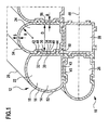
- a first embodiment of a pressure tank which is shown in Fig. 1 and there designated as a whole by 10, comprises a cell assembly 12 from one A plurality of cells 14.
- the cells can be both in rows and in Columns may be arranged as shown in Fig. 1. But it is also possible that only one row is provided.
- a cell 14 there is a receiving chamber delimited by chamber walls 16 18 formed which the fluid, for example natural gas, hydrogen or methanol, receives.
- the absorbed fluid is under pressure.
- the cells 14 are independent units and in particular have rigid chamber walls 16 on.
- a single cell 14 extends in a longitudinal direction 20.
- the longitudinal directions 20 of all cells in the cell network 12 are essentially parallel to each other.
- FIG. 1 is an upper one and one on the left outside Cell 22 connected to its cell 24 adjacent to the upper right.
- Cell 22 in turn is connected to its cell 26, which is adjacent downwards.
- the cell 24 is also connected to its cell 28, which is adjacent downwards.
- the Cells 26 and 28 that are laterally adjacent are also connected to each other.
- Cell 28 is shown in FIG Example of a completely internal cell, which is not part of the cell network has outward-facing outer wall.
- the cell network 12 can, for example thereby achieve that the adjoining chamber walls 16 adjacent cells are welded together.
- the neighboring ones Chamber walls of adjacent cells are anchored to one another.
- the cells 14 are designed so that they have a substantially flat chamber wall have, which faces the adjacent cell.
- the cells 14 includes the cell 22 a chamber wall 30 facing the cell 24 with an in substantially flat inner surface 32 and substantially flat outer surface 34th
- Cell 24 includes a chamber wall 36 with a substantially flat one Inner surface 38 and a substantially flat outer surface 40, which the Outer surface 34 of the cell 22 faces.
- the cell 22 further comprises a chamber wall 43, which essentially is perpendicular to the chamber wall 30 and a substantially flat, one Outer surface of the adjacent chamber wall 45 facing the cell 26 Has outer surface.
- Elevations are spaced above the outer surface 34 of the chamber wall 30 42, 44 are formed which extend parallel to one another in the longitudinal direction 20.
- Such an elevation 42, 44 widens in the form of a dovetail in a transverse direction 46 to the longitudinal direction 20 with a trapezoidal cross-section.
- a width of such an elevation 42, 44 is thereby at a base at the base surface 34 of the chamber wall 30 smaller than at a distance from this outer surface 34.
- the elevations 42, 44 serve as positive locking elements around the chamber walls 30 and 36 can be positively anchored to each other.
- the Chamber wall 36 each adapted to the elevations 42, 44 wells 48, 50 based on their outer surface 40. These depressions 48, 50 serve each for receiving the elevations 42, 44.
- the depressions 48, 50 are designed accordingly dovetail-shaped, their Width increased from the outer surface 40 to just the elevations 42, 44 to record.
- the cell 22 is on the cell 24 in the longitudinal direction 20 can be pushed on or the cell 24 can be pushed onto the cell 22. however the movement in the transverse direction 46 is blocked if the elevation in each case 42 dips into the depression 48 and the elevation 44 into the depression 50 dips. It is then cells 22 and 24 with respect to transverse movements Longitudinal direction 20 anchored to each other.
- cell 22 can be connected to cell 26, which Connect cell 24 to cell 28 and connect cell 26 to cell 28. By anchoring adjacent cells to one another finally the cell network 12 is formed.
- such outer walls are edge-free with the rest Chamber walls connected to avoid peaks in the voltage load.
- an outer chamber wall is curved (rounded) and in particular rounded in a circle.
- Cell 22 for example has an outer wall 52 which is integral with the chamber walls 43 and 30 sits. It sits on the outer wall 43 that in the transition no edge is formed, that is, the tangent of its inner surface at least at the transition with the tangent of the inner surface of the chamber wall 43 coincides. The same applies to the transition of the outer wall 52 on the Chamber wall 30.
- the wall thickness of the outer wall 52 is essentially everywhere equal.
- An outer wall 54 of the cell 24 is semicircular in cross section with a radius R.
- the wall thickness S is essentially everywhere equal.
- the wall thickness S of an outer wall 52 or 54, measured in mm, in the range between P / 60 and P / 30 is, where P is the internal pressure, measured in bar.
- P the internal pressure
- the transverse width D is preferably between P / 6 and P / 4 (D in mm and P in cash).
- a double wall thickness B of Adjacent and adjacent chamber walls in the area between is two times S and five times S.
- the width B corresponds to the distance between the respective inner surfaces of neighboring Chamber walls of adjacent cells, for example the distance between the Inner surfaces 32 and 38 of chamber walls 30 and 36.
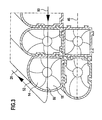
- a cell network 60 in turn a plurality of cells 62 anchored to one another, 64, 66, 68, 70, etc.
- adjacent chamber walls 72, 74 are more adjacent Do not provide cells with elevations, but only with depressions 76, 78 (chamber wall 72) and 80, 82 (chamber wall 74). These are dovetail-shaped and basically the same as above described in connection with the wells 48 and 50.
- each pair of recesses 76, 80 and 78, 82 84 or 86 is provided, which is formed in one piece and has an adapted double dovetail shape with an extension in the longitudinal direction 20.
- Such an intermediate element 84 or 86 leaves then slide into the pair of recesses 76, 80 or 78, 82. at immersed intermediate elements 84 and 86 in turn is the transverse movement the interconnected and anchored cells 62 and 64 locked.
- adjacent cell walls of adjacent cells instead of indentations only have elevations. Accordingly, then be designed an intermediate element on which the cells with the Let elevations be postponed. This intermediate element must then be one Show width that wells can be formed in it.
- the individual cells 14 and 62 as extruded profiles these can be positioned against each other in their longitudinal direction 20 while through the corresponding positive locking elements on adjacent chamber walls neighboring cells block the transverse movement in the Direction 46 can be reached.
- the receiving chambers 18 are at the front in relation to the longitudinal direction 20 and closed at the rear with a cover element 88 (FIG. 3). It can it should be provided that each cell 14 separately with such a cover element 88 is closed or the several cover elements for several Cells are connected.
- a cover element 88 is provided with chamber walls of the corresponding cell 14 especially welded.
- a cover element 88 is held on the cell composite 12 or additionally secured by a fiber composite material is wound around the cell assembly 12. This is in Fig. 3 indicated by reference numeral 90.
- the one end of the cell network 12 fibers laid transversely to the longitudinal direction 20, for example in the transverse direction 46, then on the outer wall, for example the outer wall 52 deflected in the direction 20, at the other end of the cell network 12 again deflected in the direction 46 and then returned in the longitudinal direction 20.
- Windings carried out in accordance with the cover elements 88 on the To hold or secure cell network 12.
- the fibers After wrapping, the fibers are impregnated with a matrix material.
- the cell network 12 in further directions is wrapped, in particular in further transverse directions to the longitudinal direction 20 to additionally secure the cell assembly 12.
- winding with the two winding directions is possible each in the transverse direction to the longitudinal direction 20, and two windings with one Winding direction in the longitudinal direction 20 and a winding direction in the respective transverse directions to this longitudinal direction 20.
- Connection elements for supplying and discharging fluid can be connected to a or several external cells of the cell network 12 can be arranged or also on cover elements 88.
- the pressure tank according to the invention can be manufactured in a simple manner. He can be formed flat over the composition as a cell network 12. by virtue of Anchoring the individual cells to one another is a great variety of shapes authorized.
- a pressure tank can be used with a corresponding Integrate design into the underbody of a motor vehicle.
- External walls can also be designed accordingly to the Pressure tank for example on flanges or the like in one To be able to adapt the motor vehicle.
- a fluid connection between individual cells 40 can be made via connection openings reach between the chamber walls of neighboring cells. It but can also be provided that corresponding connections via the Cover elements 88 are made.
- the chamber walls act under pressure due to the absorbed Fluids forces that put a corresponding strain on them. Over the arched Chamber walls that are particularly kink-free and edge-free with the rest Chamber walls connected to form a corresponding receiving chamber are, these forces can be absorbed over a large area, and in convert essentially pure - unidirectional - tensile forces. The corresponding Tensile stresses can then be reduced by reducing material take up. At the same time, these tensile forces can be at least partially derived and in particular lead to the opposite side. There one curved chamber wall on the opposite side the same forces experiences, forces can be determined in certain, by the structure of the pressure tank ideally derive predetermined directions, so that overall the wall load is optimized and is also minimized.
- the effective power transmission directions for deriving the tensile forces are thereby in all three spatial directions, that is in the longitudinal directions 20 and the two transverse directions along the chamber walls.
- the width of a receiving space is advantageously in the range between 30 mm and 70 mm and in particular between 20 mm and 60 mm.
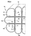
- cells 102 are arranged in a cell network 104.
- the cell assembly 104 comprises external cells 106a and 106b, which have an outer side facing the outer space and are arranged at the end of both a row and a column.
- external cells 108a, 108b are provided, which one for Have exterior facing outside and either a row or complete a column.
- outer chamber walls of the outer cells 106a, 106b and 108a, 108b are curved as described above.
- the cell network 104 is symmetrical with respect to a mirror plane 110 trained.
- Cells that are related to the mirror plane 110 symmetrically opposite, have the same wall design.
- the outer cells 106a and 106b are symmetrical with respect to the mirror plane 110.
- mirror plane 110 oriented at right angles to mirror plane 110 provided, to which the cell network is mirror-symmetrical.
- each cell with to form a cell network each neighboring cell is connected via the chamber walls.
- a corresponding one Cell network is shown in FIG. 1.
- inner cells 70 are over opposite chamber walls connected to adjacent cells, whereby the connection only takes place over two sides and not over four sides.
- each external cell (outer cell) with the neighboring two outer cells over the neighboring ones Chamber walls is connected.
- 4 is the cell 108b with the Cell 106b via a chamber wall 112, 114 facing each other arranged connection 116 connected. This connection is about in particular a positive connection as described above.
- Cell 106b is also connected to the adjacent outer cell 108a adjoining chamber walls 118 and 120 are connected. At a corresponding connection 122 is in particular a positive connection.
- Internal cells such as cells 124, 126 according to FIG. 4 are in the Cell network 104 held by exerting pressure on the surrounding cells.
- Tie rods 128 are preferably provided, which are between one another facing chamber walls transverse and in particular perpendicular to the Mirror plane 110 run. These tie rods clamp outside cells (for example, cells 106a and 106b in Fig.) in a direction transverse to Forces mirror plane 110 with one another or via them, defined forces can be derived.
- tie rods 128 are preferably at the corresponding connection points fixed at which the related to a direction parallel to the mirror plane 110 neighboring cells connected to each other via the chamber walls are.
- Tie rods 130 are also provided, which are essentially parallel to the Mirror plane 110 run and corresponding cells on opposite Brace the sides of the pressure tank together.
- the tension direction is there transversely and in particular perpendicular to the tensioning direction of the tie rods 130.
- the tie rods 128, 130 refer to the mirror plane 110 and the other mirror plane opposite outer cells with each other coupled with regard to the power dissipation and in particular braced together. Due to the transverse and in particular perpendicular lying tension directions is an additional securing of the hold of the cell network 104 causes.
- the tie rods 128, 130 are spaced apart in a longitudinal direction 132 of the pressure tank arranged. As a result, they form a cubic tie rod grid.
- the Anchor points for the tie rods are the connecting points 116, 122, etc., above which external cells 106b, 108b and 106a, 108a are connected to one another are.
- the tie rods 128, 130 extend between opposite connections through the cell network 102.
- tie rods that are only on the Extend area of a cell; for example, a tie rod can serve only connect neighboring cells directly. (In the embodiment 4 adjacent cells are only indirectly with each other coupled via the tie rods 128, 130.
- a cell network 136 is again provided with a plurality of cells 138. Adjacent cells and at least outer neighboring cells are over the mutually facing Chamber walls connected together.
- 138 free spaces between adjacent cells 140 are formed or arranged, which serve, for example, lines such as exhaust lines, electrical lines, hydraulic lines, Take fuel lines, etc.
- the free spaces are in a profile structure 142 formed which is made of a metallic material or a Plastic material is made.
- a profile structure is designed that chamber walls of cells 138 which are adjacent to profile structure 142 are stabilized by this. Examples are corresponding Bracing provided.
- the profile structure 142 is also designed so that it over the Pressure tank 134 protrudes and a support structure is formed with their help, which, for example, for fixing the pressure tank 134 to a vehicle serves. It can also be used to fix other elements to the pressure tank serve.
Landscapes
- Engineering & Computer Science (AREA)
- Mechanical Engineering (AREA)
- General Engineering & Computer Science (AREA)
- Filling Or Discharging Of Gas Storage Vessels (AREA)
- Pressure Vessels And Lids Thereof (AREA)
Applications Claiming Priority (2)
| Application Number | Priority Date | Filing Date | Title |
|---|---|---|---|
| DE10217245 | 2002-04-15 | ||
| DE10217245A DE10217245A1 (de) | 2002-04-15 | 2002-04-15 | Drucktank |
Publications (3)
| Publication Number | Publication Date |
|---|---|
| EP1355105A2 true EP1355105A2 (fr) | 2003-10-22 |
| EP1355105A3 EP1355105A3 (fr) | 2007-01-24 |
| EP1355105B1 EP1355105B1 (fr) | 2016-05-18 |
Family
ID=28458904
Family Applications (1)
| Application Number | Title | Priority Date | Filing Date |
|---|---|---|---|
| EP03008402.4A Expired - Lifetime EP1355105B1 (fr) | 2002-04-15 | 2003-04-11 | Réservoir sous pression |
Country Status (2)
| Country | Link |
|---|---|
| EP (1) | EP1355105B1 (fr) |
| DE (1) | DE10217245A1 (fr) |
Cited By (4)
| Publication number | Priority date | Publication date | Assignee | Title |
|---|---|---|---|---|
| WO2016057022A1 (fr) * | 2014-10-07 | 2016-04-14 | United Technologies Research Center | Ensemble récipient sous pression et procédé de fabrication |
| US10221999B2 (en) | 2014-10-07 | 2019-03-05 | United Technologies Corporation | Pressure vessel fluid manifold assembly |
| US11525545B2 (en) | 2014-10-07 | 2022-12-13 | Raytheon Technologies Corporation | Composite pressure vessel assembly and method of manufacturing |
| FR3143709A1 (fr) * | 2022-12-14 | 2024-06-21 | Faurecia Systemes D'echappement | Réservoir modulaire pour gaz sous pression |
Families Citing this family (3)
| Publication number | Priority date | Publication date | Assignee | Title |
|---|---|---|---|---|
| DE102010043645B4 (de) | 2010-11-09 | 2012-12-06 | Deutsches Zentrum für Luft- und Raumfahrt e.V. | Drucktankverbund |
| DE102021121433A1 (de) | 2021-08-18 | 2023-02-23 | Deutsche Institute Für Textil- Und Faserforschung Denkendorf | Druckbehälter und Verfahren zu dessen Herstellung |
| GB202210492D0 (en) * | 2022-07-18 | 2022-08-31 | Polar Tech Management Group Limited | Storage device |
Citations (1)
| Publication number | Priority date | Publication date | Assignee | Title |
|---|---|---|---|---|
| US5577630A (en) | 1995-02-02 | 1996-11-26 | Thiokol Corporation | Composite conformable pressure vessel |
Family Cites Families (9)
| Publication number | Priority date | Publication date | Assignee | Title |
|---|---|---|---|---|
| US3269389A (en) * | 1963-03-11 | 1966-08-30 | Bernard L Meurer | Compartmental dispensing container for nose and throat preparations |
| FR96255E (fr) * | 1965-12-16 | 1972-06-16 | Rodrigues Edouard Georges Dani | Procédé de fabrication de réservoirs et reservoirs ainsi obtenus. |
| US3955715A (en) * | 1975-03-13 | 1976-05-11 | Topor Alan C | Bath and shower modular dispenser arrangement |
| US4919293A (en) * | 1989-06-02 | 1990-04-24 | Paul Buckley | Multi-unit dispensing container assembly |
| US5316159A (en) * | 1991-03-01 | 1994-05-31 | Plastic Processing Corporation | Dual bottle container |
| US6006935A (en) * | 1998-02-05 | 1999-12-28 | Driver; Peter | Detachable multi-container fuel tank |
| FR2781555B1 (fr) * | 1998-07-22 | 2000-10-13 | Guy Negre | Concept et procede de fabrication de reservoir de fluide, d'air comprime ou autre gaz a haute pression |
| BR0010305B1 (pt) * | 1999-05-03 | 2010-02-09 | grupo de màdulos de fechamento e vaso de pressço de multi-cÉlula. | |
| FR2813378B1 (fr) * | 2000-08-28 | 2002-10-31 | Renault | Dispositif de stockage de fluide sous pression et/ou de reacteurs generant des fluides sous pression, en particulier pour vehicules automobiles |
-
2002
- 2002-04-15 DE DE10217245A patent/DE10217245A1/de not_active Ceased
-
2003
- 2003-04-11 EP EP03008402.4A patent/EP1355105B1/fr not_active Expired - Lifetime
Patent Citations (1)
| Publication number | Priority date | Publication date | Assignee | Title |
|---|---|---|---|---|
| US5577630A (en) | 1995-02-02 | 1996-11-26 | Thiokol Corporation | Composite conformable pressure vessel |
Cited By (7)
| Publication number | Priority date | Publication date | Assignee | Title |
|---|---|---|---|---|
| WO2016057022A1 (fr) * | 2014-10-07 | 2016-04-14 | United Technologies Research Center | Ensemble récipient sous pression et procédé de fabrication |
| CN107257897A (zh) * | 2014-10-07 | 2017-10-17 | 联合工艺公司 | 压力容器组件及其形成方法 |
| US10221999B2 (en) | 2014-10-07 | 2019-03-05 | United Technologies Corporation | Pressure vessel fluid manifold assembly |
| US10648616B2 (en) | 2014-10-07 | 2020-05-12 | United Technologies Corporation | Pressure vessel assembly and method of forming |
| US11525545B2 (en) | 2014-10-07 | 2022-12-13 | Raytheon Technologies Corporation | Composite pressure vessel assembly and method of manufacturing |
| US11898701B2 (en) | 2014-10-07 | 2024-02-13 | Rtx Corporation | Composite pressure vessel assembly and method of manufacturing |
| FR3143709A1 (fr) * | 2022-12-14 | 2024-06-21 | Faurecia Systemes D'echappement | Réservoir modulaire pour gaz sous pression |
Also Published As
| Publication number | Publication date |
|---|---|
| EP1355105B1 (fr) | 2016-05-18 |
| DE10217245A1 (de) | 2003-11-06 |
| EP1355105A3 (fr) | 2007-01-24 |
Similar Documents
| Publication | Publication Date | Title |
|---|---|---|
| EP3625496B1 (fr) | Véhicule muni d'un système de stockage servant à stocker et fournir un gaz sous pression et système de stockage pour véhicule | |
| AT394225B (de) | Baukoerper | |
| DE102020124252A1 (de) | Speichermodul mit mehreren röhrenförmigen Drucktanks | |
| EP1355105B1 (fr) | Réservoir sous pression | |
| DE69801533T2 (de) | Lagergestell für Kernreaktorbrennstabbündel mit durch Rahmen festgehaltenen Neutronenabsorberelementen | |
| EP1355107B1 (fr) | Réservoir sous pression | |
| DE10126234A1 (de) | Aufbaustruktur für ein Kraftfahrzeug mit zusammengesetzten Trägern | |
| EP1355106B1 (fr) | Réservoir sous pression | |
| DE202008018024U1 (de) | Distanzplatte | |
| DE1559490B1 (de) | Bewehrungselement fuer Balken und Stuetzen aus Stahlbeton | |
| DE29518886U1 (de) | Stahlbauskelettkonstruktion | |
| DE102019116886A1 (de) | Verstärkter Zylinderkopf | |
| DE19804854C2 (de) | Mast für ein Handhabungsgerät, insbesondere ein Regalbediengerät | |
| DE3045389C2 (fr) | ||
| DE19713246C2 (de) | Zylinderkopf einer Mehrzylinder-Brennkraftmaschine | |
| DE2261867C3 (de) | Metallträger | |
| DE29909827U1 (de) | Druckbehälter | |
| DE102022205448B3 (de) | Hochvolt-Batteriesystem mit einem Batteriegehäuse, das durch mindestens einen Träger in mehrere Batteriegehäuseteilräume aufgeteilt ist | |
| AT390466B (de) | Bauelement zum errichten von waenden | |
| DE8620412U1 (de) | Sitzelement, insbesondere für verbundartige Anordnungen | |
| DE19949650C2 (de) | Träger aus Profilstäben | |
| WO2001051741A1 (fr) | Support de grille | |
| DE102017107850A1 (de) | Gerüstriegel mit integriertem Unterzug | |
| DE19739253A1 (de) | Leichtbauweise mit Gittern | |
| DE202025106664U1 (de) | Stahlhalle mit Rahmenkonstruktion |
Legal Events
| Date | Code | Title | Description |
|---|---|---|---|
| PUAI | Public reference made under article 153(3) epc to a published international application that has entered the european phase |
Free format text: ORIGINAL CODE: 0009012 |
|
| AK | Designated contracting states |
Kind code of ref document: A2 Designated state(s): AT BE BG CH CY CZ DE DK EE ES FI FR GB GR HU IE IT LI LU MC NL PT RO SE SI SK TR |
|
| AX | Request for extension of the european patent |
Extension state: AL LT LV MK |
|
| PUAL | Search report despatched |
Free format text: ORIGINAL CODE: 0009013 |
|
| AK | Designated contracting states |
Kind code of ref document: A3 Designated state(s): AT BE BG CH CY CZ DE DK EE ES FI FR GB GR HU IE IT LI LU MC NL PT RO SE SI SK TR |
|
| AX | Request for extension of the european patent |
Extension state: AL LT LV MK |
|
| RIC1 | Information provided on ipc code assigned before grant |
Ipc: F17C 13/08 20060101ALI20061219BHEP Ipc: F17C 1/00 20060101AFI20030813BHEP Ipc: F17C 1/14 20060101ALI20061219BHEP |
|
| 17P | Request for examination filed |
Effective date: 20070712 |
|
| AKX | Designation fees paid |
Designated state(s): DE FR IT |
|
| 17Q | First examination report despatched |
Effective date: 20071107 |
|
| GRAP | Despatch of communication of intention to grant a patent |
Free format text: ORIGINAL CODE: EPIDOSNIGR1 |
|
| INTG | Intention to grant announced |
Effective date: 20150804 |
|
| INTG | Intention to grant announced |
Effective date: 20160107 |
|
| GRAS | Grant fee paid |
Free format text: ORIGINAL CODE: EPIDOSNIGR3 |
|
| GRAA | (expected) grant |
Free format text: ORIGINAL CODE: 0009210 |
|
| AK | Designated contracting states |
Kind code of ref document: B1 Designated state(s): DE FR IT |
|
| REG | Reference to a national code |
Ref country code: DE Ref legal event code: R096 Ref document number: 50315467 Country of ref document: DE |
|
| PG25 | Lapsed in a contracting state [announced via postgrant information from national office to epo] |
Ref country code: IT Free format text: LAPSE BECAUSE OF FAILURE TO SUBMIT A TRANSLATION OF THE DESCRIPTION OR TO PAY THE FEE WITHIN THE PRESCRIBED TIME-LIMIT Effective date: 20160518 |
|
| REG | Reference to a national code |
Ref country code: DE Ref legal event code: R097 Ref document number: 50315467 Country of ref document: DE |
|
| REG | Reference to a national code |
Ref country code: FR Ref legal event code: PLFP Year of fee payment: 15 |
|
| PLBE | No opposition filed within time limit |
Free format text: ORIGINAL CODE: 0009261 |
|
| STAA | Information on the status of an ep patent application or granted ep patent |
Free format text: STATUS: NO OPPOSITION FILED WITHIN TIME LIMIT |
|
| 26N | No opposition filed |
Effective date: 20170221 |
|
| REG | Reference to a national code |
Ref country code: FR Ref legal event code: PLFP Year of fee payment: 16 |
|
| PGFP | Annual fee paid to national office [announced via postgrant information from national office to epo] |
Ref country code: FR Payment date: 20190320 Year of fee payment: 17 |
|
| PGFP | Annual fee paid to national office [announced via postgrant information from national office to epo] |
Ref country code: DE Payment date: 20190318 Year of fee payment: 17 |
|
| REG | Reference to a national code |
Ref country code: DE Ref legal event code: R119 Ref document number: 50315467 Country of ref document: DE |
|
| PG25 | Lapsed in a contracting state [announced via postgrant information from national office to epo] |
Ref country code: FR Free format text: LAPSE BECAUSE OF NON-PAYMENT OF DUE FEES Effective date: 20200430 Ref country code: DE Free format text: LAPSE BECAUSE OF NON-PAYMENT OF DUE FEES Effective date: 20201103 |