EP1355211A2 - Kompensation von Zylinderschwingungen in bedruckstoffverarbeitenden Maschinen - Google Patents
Kompensation von Zylinderschwingungen in bedruckstoffverarbeitenden Maschinen Download PDFInfo
- Publication number
- EP1355211A2 EP1355211A2 EP03006211A EP03006211A EP1355211A2 EP 1355211 A2 EP1355211 A2 EP 1355211A2 EP 03006211 A EP03006211 A EP 03006211A EP 03006211 A EP03006211 A EP 03006211A EP 1355211 A2 EP1355211 A2 EP 1355211A2
- Authority
- EP
- European Patent Office
- Prior art keywords
- cylinder
- compensation device
- compensation
- processing machine
- material processing
- Prior art date
- Legal status (The legal status is an assumption and is not a legal conclusion. Google has not performed a legal analysis and makes no representation as to the accuracy of the status listed.)
- Granted
Links
Images



Classifications
-
- B—PERFORMING OPERATIONS; TRANSPORTING
- B41—PRINTING; LINING MACHINES; TYPEWRITERS; STAMPS
- B41F—PRINTING MACHINES OR PRESSES
- B41F13/00—Common details of rotary presses or machines
- B41F13/004—Electric or hydraulic features of drives
- B41F13/0045—Electric driving devices
-
- B—PERFORMING OPERATIONS; TRANSPORTING
- B41—PRINTING; LINING MACHINES; TYPEWRITERS; STAMPS
- B41F—PRINTING MACHINES OR PRESSES
- B41F13/00—Common details of rotary presses or machines
- B41F13/08—Cylinders
- B41F13/085—Cylinders with means for preventing or damping vibrations or shocks
-
- F—MECHANICAL ENGINEERING; LIGHTING; HEATING; WEAPONS; BLASTING
- F16—ENGINEERING ELEMENTS AND UNITS; GENERAL MEASURES FOR PRODUCING AND MAINTAINING EFFECTIVE FUNCTIONING OF MACHINES OR INSTALLATIONS; THERMAL INSULATION IN GENERAL
- F16F—SPRINGS; SHOCK-ABSORBERS; MEANS FOR DAMPING VIBRATION
- F16F15/00—Suppression of vibrations in systems; Means or arrangements for avoiding or reducing out-of-balance forces, e.g. due to motion
- F16F15/02—Suppression of vibrations of non-rotating, e.g. reciprocating systems; Suppression of vibrations of rotating systems by use of members not moving with the rotating systems
-
- B—PERFORMING OPERATIONS; TRANSPORTING
- B65—CONVEYING; PACKING; STORING; HANDLING THIN OR FILAMENTARY MATERIAL
- B65H—HANDLING THIN OR FILAMENTARY MATERIAL, e.g. SHEETS, WEBS, CABLES
- B65H2557/00—Means for control not provided for in groups B65H2551/00 - B65H2555/00
- B65H2557/20—Calculating means; Controlling methods
- B65H2557/264—Calculating means; Controlling methods with key characteristics based on closed loop control
- B65H2557/2644—Calculating means; Controlling methods with key characteristics based on closed loop control characterised by PID control
Definitions
- the invention relates to a compensation device for vibrations Angle size in a printing material processing machine, with an assigned on the angle size acting actuator, the compensation device for the Angular magnitude curve representative signal is supplied and the Compensation device generates an output signal for the actuator.
- These impairments can lead to printing problems, especially to so-called duplication.
- mechanically decoupled parts of a substrate processing machine, in particular two or more printing unit groups of a sheet processing Printing press such impairments can become relevant: From the Vibrations resulting fluctuations in the rotational angle differences on the circumferences of a first and a second cylinder lead directly to one when the sheet is handed over corresponding increase in the circumferential passport to the sheet transfer angle between the separate printing units involved.
- the object of the present invention is to prevent undesirable vibrations of a cylinder or several cylinders in printing material processing machines, in particular Printing machines, reduce or eliminate them.
- the compensation device for vibrations has one Angle size in a printing material processing machine, with an assigned, preferably downstream of the compensation device, on the angular size acting actuator, at least one filter in the form of a transfer function or a sum of transfer functions, the frequency parameters of which to correspond to compensating vibration frequencies, by the effect of which Output signal of the compensation device for the actuator to at least one of the compensating discrete frequency from that supplied to the compensation device for the angular size curve, more precisely for the temporal curve or the temporal Change in the value of the angular size, representative signal is obtained.
- the Angle size can be a rotation angle of a cylinder or a rotation angle difference of a first and second cylinders.
- the vibrations that occur can be represented discretely in the sense of how they are formed by a superposition of vibrations with discrete frequencies. With sufficient precision, the vibrations occurring are finite Number of vibrations can be represented. It is known that the vibrations that occur depend on the operating state of the printing material processing machine. On The parameter with a particularly strong influence is the printing speed.
- the frequency parameters necessary for the compensation device according to the invention are either preset or are in operation during the Printing material processing machine adjustable or changeable.
- An attitude can for example, based on the operating state, as in the Machine control is shown.
- the machine control can be in active connection with the compensation device according to the invention and the frequency parameters influence or change. In particular, the frequency parameters be speed dependent.
- the compensation device according to the invention can be advantageous and simple Way to compensate for integer or non-integer orders of Vibrations related to the machine frequency are used. It is for them Compensation device requires no exact knowledge of the process parameters. Therefore, even with strongly fluctuating processes (process parameters, Process transfer functions) stability can be achieved. To ensure stability only knowledge of the stability range of the process parameters is required.
- a Embodiment of the compensation device includes with little computing effort Second order filter.
- the compensation device can be particularly advantageous for Compensation of vibrations are used, whose energy compared to that Energy of a rotational movement of the angular size is small.
- a compensation method for vibrations Angle size in a printing machine on the angle size with acted on an actuator in such a way that vibrations of the angular size are reduced, wherein a signal representative of the angular size curve is determined and the Compensation device for generating an output signal for the actuator is fed.
- the output signal of the compensation device is effective at least one filter in the form of a transfer function or a sum of Transfer functions, the frequency parameters of which are to be compensated Vibration frequencies correspond to at least one of the discrete to be compensated Frequencies obtained from the signal.
- the compensation device is the transfer function harmonic for each of the frequencies to be compensated, thus a sine or cosine or corresponding phase-shifted function.
- the Transfer functions are each in the Laplace area (S area, for continuous signals) or Z range.
- Basic mathematical properties the Laplace transform and the Z transform are, for example, in "Taschenbuch der Mathematik" by I. N. Bronstein and K. A. Semendjajew, 24th edition, Harri Deutsch, Thun and Frankfurt am Main, Germany, 1989.
- the representative signal for the angular size curve can be a time series, one by one Signal sequences determined or sampled at times. In other words expressed, the representative signal can be from a (preferably time-ordered) row of measured values of the angular size at different times.
- the current The angle size curve can be known at discrete support points. Alternatively, you can a continuous representative signal can also be generated.
- a representative signal can be generated by an angular position encoder. It can be direct or indirect, that is, unprocessed or unmodified or processed and modified by Compensation device are supplied. Processing (modification) can For example, it may be necessary to compensate for systematic errors in the measurement (Calibration). In the procedure according to the invention, the sampling time can vary from Period duration of the vibration to be compensated is independent and is preferred independently.
- the compensation device comprises a Computing device in which a program runs, the at least one section in which the output signal from the representative signal is effective the transfer function is obtained on the representative signal.
- the transfer function can be stored in a memory and a The program has steps according to a calculation rule, such as through the transformation Output signal is obtained from the representative signal. especially the Calculation of the output signal as one corresponding to the transfer function Difference equation from values of the input signal to one or more Times and optionally from values of the output signal for one or more previous times are provided.
- phase shift element to the filter upstream or downstream.
- Filters and phase shift elements can also be integrated.
- the phase shift element can also be in the filter be included.
- the phase shift element can be set to a discrete frequency multiple discrete frequencies or act on a continuum of frequencies. Different expressed, for each frequency to be compensated, a phase shift element be provided or a phase shift element acts on at least a number the frequencies to be compensated.
- the stability of the Compensation also by choosing the phase of the harmonic transfer function be ensured.
- the compensation device according to the invention for vibrations of an angle variable can be assigned to the control element in a control device for this angle variable in a printing material processing machine, with an angle variable transmitter, a control element, an actuator acting on the angle variable, such that the output signal of the compensation device is superimposed on the output signal of the control element ,
- the representative signal can represent the value of the angular variable or the value of the angular variable change or the value of the angular variable acceleration.
- the control element preferably has an input for actual values of the representative signal of the angular variable and an input for target values of the representative signal of the angular variable.
- a control method according to the invention for an angle variable in of a printing material processing machine by influencing the angle size an actuator such that differences between actual values and setpoints of the Angle size can be reduced includes compensation for vibrations of the Angle size with a compensation method according to the invention.
- a printing unit according to the invention a printing material processing machine with at least one cylinder. It draws itself by a compensation device according to the invention and / or a control device according to the invention, which is assigned to the cylinder.
- a printing unit according to the invention can be used in a Printing material processing machine with at least one first cylinder and one second cylinder, a compensation device according to the invention and / or a Control device according to the invention, which the first cylinder and the second Cylinder is assigned.
- a printing group consists of a number of printing groups. Those are preferred Printing units of a printing unit group adjacent to each other. In other words, the Printing material goes from one printing unit to the other printing unit along its Transport route through the printing press.
- the compensation device according to the invention or the inventive Control device can be in a printing press with a continuous gear train or in a printing press with a separate gear train.
- a printing press can separate points between printing units or Printing unit groups exist, the drives of the printing units or Printing unit groups are separated from each other.
- the printing units or printing unit groups viewed individually, they can have one or more drives.
- a printing press according to the invention has at least one according to the invention Printing unit and / or a printing unit group according to the invention. Furthermore alternatively, a printing press according to the invention can have one or more Separation points, which each have boundaries between printing units or printing unit groups form and over which the substrate between not mechanically accurate synchronized cylinders is passed, with a first for each separation point Cylinder and a second cylinder, between which the separation point lies, one compensation device according to the invention and / or an inventive device Control device which is assigned to the first cylinder and the second cylinder is.
- a printing machine according to the invention with at least one first Cylinder and a second cylinder, which mechanically decouples from the first cylinder is characterized by a compensation device according to the invention, which the is assigned to the first cylinder and the second cylinder, and / or an inventive Control device from which the first cylinder and the second cylinder assigned.
- a printing press according to the invention with at least a first Cylinder can by a compensation device according to the invention, which the is assigned to the first cylinder, and / or a control device according to the invention, which is assigned to the first cylinder.
- the printing press can be a web processing (roll processing) or sheet processing machine.
- the machine can use various methods Print:
- the printing process can be a direct or act indirect flat printing, offset printing, flexographic printing or the like.
- typical Printing materials are paper, cardboard, cardboard, organic polymer film or the like.
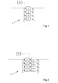
- Figure 1 shows a schematic representation of the structure of an inventive Compensation device.
- the compensation device preferably contains a harmonic transfer function whose angular frequency corresponds to the angular frequency ⁇ n to be compensated.
- the harmonic transfer function can be a cosine transfer function or a sine transfer function or a weighted sum of a cosine and a sine transfer function.
- a cosine transfer function is first considered for the sake of clarity.
- the process is the transfer function from the output of the compensation device 9 to the input of the compensation device 9. In typical suitable designs, a phase shift of -90 ° is only achieved at angular frequencies greater than 100 s -1 .
- an sinusoidal disturbance is completely eliminated - in other words, adjusted to a setpoint 0 - if a model of the disturbance is contained in the compensation device and the closed compensation circuit is stable.
- the order of the angular frequency to be compensated can be integer or non-integer.
- a printing material processing machine has a controller which has the average machine speed as the target speed.
- the parameter b n must be recalculated in accordance with equation (3) in equations (1), (2) and (4) if the mean machine speed or setpoint speed changes.
- the compensation device achieves an elimination of the sinusoidal disturbance without a complex calculation of trigonometric functions and can therefore be used in connection with simple control computers.
- phase of the process can always be adjusted so that it lies in this stable range.
- the transfer function has an infinitely high gain for the angular frequency ⁇ n and a gain dependent on k n for other frequencies, which decreases with the difference between the angular frequency to be compensated and the frequency under consideration.
- the consideration can therefore be reduced to the angular frequency to be compensated.
- the phase shift of the process for this frequency to be compensated is in a range from -90 ° to + 90 °, the sign reversal in the compensation circuit ensures stability. With a relatively rigid coupling of the actuator to the compensation axis, this is usually fulfilled for small orders.
- phase shift lies in a range from -180 ° to 0 °
- a phase increase of + 90 ° can be achieved by switching a differentiating element before or after the compensation device. This is particularly useful for higher orders, since the process typically has a phase shift with a negative sign.
- the use of a differentiator corresponds to the use of a speed signal instead of an angle signal for compensation.
- the compensation approach according to the invention with a harmonic transfer function applies very generally according to the internal interference model (internal model principle) for a large number of transfer functions G R for continuous-time or discrete-time signals which contain a sine or cosine transfer function as a component and therefore the harmonic signal component of the angular frequency required for compensation can generate ⁇ n .
- compensation is possible with the following cosine transfer functions or with the following sine transfer functions, possibly with a stability-shifting phase shift element G V ( z ):
- phase shift element G V ( z ) Without a phase shift element G V ( z ) with a small k R stability with the cosine transfer function there is approximately for phase shifts ⁇ P of the process at the compensation angular frequency from -90 ° to + 90 ° and with the sine transfer function for phase shifts ⁇ P of the process at the compensation angular frequency from 0 ° to + 180 °.
- the transfer functions can be converted into one another by means of a suitable phase shift element.
- the cosine transfer function without a holding element corresponds to this phase shift element G V ( z )
- phase shift element Without the use of a phase shift element, stability can also be achieved by selecting cosine or sine transfer functions for compensation with one of the signs + and -, for example by where ⁇ and P is the phase shift ⁇ P of the process at the compensation frequency measured in the range -180 ° ... + 180 °. Both options ensure stability for small gain factors k R. For large k R , it depends on the process whether stability is given.
- a maximum robustness of the method is maximum robustness due to a parallel use of sine and cosine transfer functions, weighted according to the measured phase shift ⁇ and P of the process at the compensation frequency, for any phase shifts of the process against fluctuations in the phase shift ⁇ P of the process.
- the cosine transfer function is weighted with cos ⁇ and P and an associated sine transfer function with sin ⁇ and P.
- the stability of the compensation is given even when the phase shift ⁇ P of the process fluctuates by up to ⁇ 90 ° at the compensation frequency in relation to the measured ⁇ and P.
- the ratio of the related sine and cosine transfer functions at the compensation frequency, the imaginary unit is i, so that these functions are orthogonal to one another there and have the same amount.
- the selected weighted addition of these functions creates harmonic overall transfer functions which are coordinated for a process with phase shift ⁇ and P at the compensation frequency.
- T AK ⁇ 2 / k R k P cos ⁇ P applies with asymptotic stability and when using the above-mentioned sine transfer functions the relationship T AS ⁇ 2 / k R k P sin ⁇ P.
- FIG. 1 shows an embodiment of a compensation device 9 with a number of filters 13 acting in parallel with harmonic transmission functions, each of which has different frequency parameters corresponding to an oscillation to be compensated for.
- the signal representing an angular size curve with vibrations to be compensated is fed to the inputs of these filters 13.
- the outputs of the filters 13 are added up. The sum thus forms the total output of the compensation device 9.
- the controller 14 of the printing material processing machine is connected to the filters 13.
- the orders to be compensated may also be predetermined and / or calculated by the controller 14 depending on the speed.
- the parameters of the harmonic transfer functions, in particular the b n according to equation (3), can be determined in the controller 14 or in a computing device of the compensation device 9. It can also be provided that the controller 14 specifies fixed circular frequencies instead of orders and / or determines them with measuring devices on the printing-material-processing machine if frequency-fixed disturbances occur.
- FIG. 2 is a schematic illustration of an advantageous development of the Construction of a compensation device according to the invention.
- the filters 13 with Transfer function are each preceded by phase shift elements 12.
- Phase shift element 12 is preferably a linear member, which phase on the The angular frequency of the filter 13 arranged downstream influences it.
- the phase shift element depending on the design, the phase only at the influence the angular frequency to be compensated or phases for any Can influence angular frequencies. Of course, only that is relevant Phase shift for the angular frequency to be compensated.
- the controller 14 determines the structure or parameters of the phase shift elements, in particular the Angular frequency and the amount and direction of the phase shift.
- phase shift elements 12 are dependent on any phase shifts of the phase shift generated by the process in the entire angular range adjustable between 0 ° and 360 °.
- phase shift element with adjustable from 0 ° to + 90 ° Phase shift used.
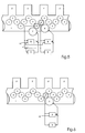
- Figure 3 relates schematically to a section of a Printing material processing machine 1 with separate gear train, two Control devices and a vibration compensation according to the invention.
- the advantageous embodiment shown relates to a transfer point between two arc-guiding cylinders, first cylinder 4 and second cylinder 5, in one Sheet printing machine with several printing units 2 and cylinders 3.
- the wheel train is separated between the first cylinder 4 and the second cylinder 5.
- the first cylinder 4 experiences an angle control by means of a control element 8 and with a first actuator 6, in a simple version with a motor.
- the second cylinder 5 also experiences one Angle control by means of a control element 8 and with a second actuator 7, in simple version with one motor.
- the control elements 8 become representative Signals for the course of the angular sizes (value of the angular size) of the assigned Cylinder, for example obtained by angular position sensors, supplied.
- the control elements 8 can be simple differential controllers or controllers which are complicated Transformations (integrations, differentiations and the like) include.
- the Actuators 6, 7 acting on the angular sizes of the assigned cylinders can be shown in a first embodiment, the individual drives of the assigned cylinders, in one second embodiment, additional auxiliary drives for the assigned cylinders, which are moved by a main drive.
- the control elements 8 become a setpoint of the representative signal, angular magnitude setpoint 10. In the context of Representation of the embodiments is here and in the following only by one Spoken angle size setpoint.
- the one presented here Embodiment requires only one compensation element 9, with which the disturbing Orders of vibrations can be removed directly from the target size. This can be done with great precision.
- Figure 4 is a schematic representation of a section of an embodiment of a Printing material processing machine 1, which several printing units 2 and more Cylinder 3 has, with a separate gear train, two control devices and two Vibration compensation according to the invention.
- a separate compensation of the vibrations on the Transfer point between the first cylinder 4 and the second cylinder 5 in the individual Angle sizes In contrast to the compensation of the Angular difference in the embodiment shown by Figure 3 takes place in the Embodiment of this Figure 4, a separate compensation of the vibrations on the Transfer point between the first cylinder 4 and the second cylinder 5 in the individual Angle sizes.
- the reduction or is advantageous in this embodiment Elimination of the absolute angular magnitude vibrations of the cylinders 4, 5, if necessary even the two machine parts, which are the first and the second cylinder include, as opposed to reducing or eliminating the relative Angular magnitude vibrations in the embodiment of Figure 3.
- a compensation takes place directly in the target values by means of two compensation elements 9, each of which are assigned to the control element 8.
- This embodiment is symmetrical for the First cylinder 4 and the second cylinder 5:
- Each of the cylinders 4, 5 is one Associated control element 8, which is a representative signal for the angular size of the Cylinder (value of the angular size) and an angular size setpoint 10 are supplied.
- a compensation element 9 is provided, the Output signal is superimposed on the output signal of the control element (Subtraction points according to control elements 8). The superimposed signals become the first Actuator 6 and the second actuator 7 supplied.
- FIG. 5 is a section of an alternative embodiment of a Printing material processing machine 1, which several printing units 2 and cylinder 3rd includes, with separate gear train, two control devices and two Vibration compensation according to the invention.
- Compensation of vibrations at a transfer point between two sheet-guiding there is a separate compensation for the first cylinder 4 and for cylinders the second cylinder 5, on the other hand, a relative compensation for the Angular difference, shown here as an example for the second cylinder 5, performed.
- This Embodiment advantageously combines an absolute reduction in Vibrations with the relative reduction in vibrations (relevant angle size for the sheet transfer).
- the first cylinder 4 is assigned a regulating element 8, the one representative signal for the angular size of the first cylinder 4 (value of the angular size) and an angle size setpoint 10 are supplied.
- Parallel to the control element 8 is a Compensation element 9 is provided, the output signal of the output signal of the Control element at the subtraction point after the control elements 8 is superimposed.
- the superimposed signal is supplied to the first actuator 6.
- the second cylinder 5 is too a control element 8 assigned to which a representative signal for the angular size of the second cylinder 5 (value of the angular size) and an angular size setpoint 10 are supplied become.
- the output signal of the compensation element 9 is the output signal of the control element 8 at a subtraction point after the Control element 8 of the second cylinder 5 superimposed.
- the superimposed signal is the second actuator 7 supplied.
- FIG. 6 shows a section of an alternative embodiment of a Printing material processing machine 1, with several printing units 2 and cylinders 3, with a control device and a vibration compensation according to the invention for a cylinder.
- the printing material processing machine 1 of this embodiment can either be a continuous gear train or an interrupted gear train exhibit.
- the use of a compensation device 9 according to the invention and the Use of a control device according to the invention with control element 8 and Compensation device 9 is not dependent on the reduction of vibrations Transfer points between sheet-guiding cylinders limited, but can be in the general to an improved regulation or compensation of Vibrations of cylinders, for example printing form cylinders, transmission or Blanket cylinder or impression cylinder, as well as rollers and rollers in ink and / or Dampening systems can be used.
- FIG 6 is an example of a control with parallel Compensation for a first cylinder 4 is shown: Using an angular position encoder, a representative signal for the course of the angular size (temporal course of the value of the Angle size) generated and the control element 8 together with a Angle size setpoint 10 supplied.
- the control element 8 can be a simple one Differential regulator or also a regulator, which complicated transformations (Integrations, differentiations and the like). That for the course of the Angular magnitude representative signal is also parallel to the compensation element 9 fed.
- Its output signal is the output signal of the control element 8 am Subtraction point after the control elements 8 overlaid.
- the superimposed signal is the first actuator 6 supplied. Because the frequency to be compensated or the compensating frequencies of the compensation element 9 can be adjusted in addition to vibrations of non-integer order compared to the machine frequency Integer order vibrations can also be compensated for.
- FIG. 7 relates to a section of an embodiment of a Printing material processing machine 1 with at least two printing units 2, which in each case a control element 8 and a vibration compensation according to the invention is assigned by a compensation element 9 for a cylinder.
- a control element 8 and a vibration compensation according to the invention is assigned by a compensation element 9 for a cylinder.
- a compensation element 9 for a cylinder With such a Embodiment can also advantageously vibrations in the gear train be reduced or even eliminated.
- Actuators 6 for example individual motors, are provided, each on cylinder 4 Act. To avoid flank changes on gears in the gear train, they are Actuators 6, for example, by the choice of the average engine torque regulate that the energy flow in the substrate processing machine 1 be nowhere Sign changes.
- Each cylinder 4 is assigned a control element 8, the one representative signal for the angular size of the associated cylinder 4 (value of the Angle size) and an angle size setpoint 10 are supplied.
- Parallel to Control element 8 a compensation element 9 is provided, the Output signal after the output signal of the control element 8 at the subtraction point the control elements 8 is superimposed. The superimposed signal is the actuator 6 fed.
- FIG. 8 is a schematic illustration of an embodiment of a Control device with a vibration compensation according to the invention for one Cylinder 5 of a web press.
- the Cylinder 5 is assigned a control element 8, to which a representative signal for the Angular size of the cylinder 5 (value of the angular size) and an angular size setpoint 10 are fed.
- a compensation element 9 is parallel to the control element 8 provided, the output signal of the output signal of the control element 8 am Subtraction point after the control elements 8 is superimposed. The superimposed signal is fed to the actuator 7.
- vibrations of non-integer order in comparison to the machine frequency can also vibrations of integer order by means of compensation element 9 according to the invention can be reduced or eliminated.
- FIG. 9 shows a section of a further alternative embodiment of a Printing material processing machine 1 with a control device and Vibration compensation according to the invention.
- This embodiment is special advantageous to use in printing material processing machines without separated wheel pull to compensate for vibrations near the first natural frequency because the first natural frequency (antinodes at the open ends and a Vibration node in between) largely extinguished here in the entire machine can be.
- the cylinders with rotary encoders are close to the Machine ends arranged.
- the printing material processing machine 1, which several Has printing units 2 and several cylinders 3, has a compensation device 9 at whose input the difference in the angular position signals of the rotary encoder of the first Cylinder 4 and the second cylinder 5 abuts.
- the output signal of the Compensation device 9 is from the output signal of the control element 8, which the Angular position signal of a third cylinder 15 and a to be compensated Angle size setpoint is supplied deducted. It is regulated by means of a first Actuator 6, which acts on the third cylinder 15.
- a first Actuator 6 which acts on the third cylinder 15.
- FIG. 10 shows another further embodiment of a printing material processor Machine 1 with a control device and an inventive Vibration compensation shown.
- This embodiment is advantageous for Interference compensation of orders that are not close to the first natural frequency lie, especially for lower frequencies than the first natural frequency.
- the Printing material processing machine 1, which several printing units 2 and more Cylinder 3 has a compensation device 9, at the input of which Angular position signal of the encoder of the first cylinder 4 is present.
- the Output signal of the compensation device 9 is from the output signal of the Control element 8, the angular position signal of a cylinder 5 to be compensated and a Angle size setpoint is supplied deducted. It is regulated by means of a first Actuator 6, which acts on the cylinder 5.
Landscapes
- Engineering & Computer Science (AREA)
- Mechanical Engineering (AREA)
- General Engineering & Computer Science (AREA)
- Physics & Mathematics (AREA)
- Acoustics & Sound (AREA)
- Aviation & Aerospace Engineering (AREA)
- Inking, Control Or Cleaning Of Printing Machines (AREA)
- Auxiliary Devices For Machine Tools (AREA)
- Rotary Presses (AREA)
- Vibration Prevention Devices (AREA)
- Feedback Control In General (AREA)
- Rolls And Other Rotary Bodies (AREA)
Abstract
Description
Bevorzugt weist das Regelelement einen Eingang für Istwerte des repräsentativen Signals der Winkelgröße und einen Eingang für Sollwerte des repräsentativen Signals der Winkelgröße auf.
- Figur 1
- eine schematische Darstellung des Aufbaus einer erfindungsgemäßen Kompensationseinrichtung,
- Figur 2
- eine schematische Darstellung einer vorteilhaften Weiterbildung des Aufbaus einer erfindungsgemäßen Kompensationseinrichtung,
- Figur 3
- einen Ausschnitt einer bedruckstoffverarbeitenden Maschine mit getrenntem Räderzug, zweier Regelungsvorrichtungen und einer erfindungsgemäßen Schwingungskompensation,
- Figur 4
- einen Ausschnitt einer Ausführungsform einer bedruckstoffverarbeitenden Maschine mit getrenntem Räderzug, zwei Regelungsvorrichtungen und zwei erfindungsgemäßen Schwingungskompensationen,
- Figur 5
- einen Ausschnitt einer alternativen Ausführungsform einer bedruckstoffverarbeitenden Maschine mit getrenntem Räderzug, zwei Regelungsvorrichtungen und zwei erfindungsgemäßen Schwingungskompensationen,
- Figur 6
- einen Ausschnitt einer alternativen Ausführungsform einer bedruckstoffverarbeitenden Maschine mit einer Regelungsvorrichtung und einer erfindungsgemäßen Schwingungskompensation für einen Zylinder,
- Figur 7
- einen Ausschnitt einer Ausführungsform einer bedruckstoffverarbeitenden Maschine, die zwei Zylinder aufweist, denen jeweils eine Regelungsvorrichtung und eine erfindungsgemäße Schwingungskompensation zugeordnet ist,
- Figur 8
- eine Ausführungsform einer Regelungsvorrichtung mit einer erfindungsgemäßen Schwingungskompensation für einen Zylinder einer Rollendruckmaschine,
- Figur 9
- einen Ausschnitt einer weiteren alternativen Ausführungsform einer bedruckstoffverarbeitenden Maschine mit einer Regelungsvorrichtung und einer erfindungsgemäßen Schwingungskompensation, und
- Figur 10
- eine andere weitere Ausführungsform einer bedruckstoffverarbeitenden Maschine mit einer Regelungsvorrichtung und einer erfindungsgemäßen Schwingungskompensation.



Bei Verwendung der oben angegebenen Cosinus-Übertragungsfunktionen gilt dagegen bei asymptotischer Stabilität die Beziehung TAK ≈ 2 / k R k Pcosϕ P und bei Verwendung der oben angegebenen Sinus-Übertragungsfunktionen die Beziehung TAS ≈ 2 / k R k Psinϕ P .
Diese Beziehungen erlauben eine eindeutige Parametrierung der Kompensation in Abhängigkeit der gemessenen Verstärkung k and P und Phasenverschiebung ϕ andP des Prozesses sowie der wählbaren Abklingkonstante TA.
- 1
- bedruckstoffverarbeitende Maschine
- 2
- Druckwerk
- 3
- Zylinder
- 4
- erster Zylinder
- 5
- zweiter Zylinder
- 6
- erster Aktuator zur Regelung des ersten Zylinders
- 7
- zweiter Aktuator zur Regelung des zweiten Zylinders
- 8
- Regelelement
- 9
- Kompensationseinrichtung
- 10
- Winkelgrößensollwert
- 11
- Bedruckstoffbahn
- 12
- Phasenverschiebungselement
- 13
- Filter mit Übertragungsfunktion
- 14
- Steuerung
- 15
- dritter Zylinder
Claims (19)
- Kompensationseinrichtung (9) für Schwingungen einer Winkelgröße in einer bedruckstoffverarbeitenden Maschine (1), mit einem zugeordneten, auf die Winkelgröße einwirkenden Aktuator (6), wobei der Kompensationseinrichtung (9) ein für den Winkelgrößenverlauf repräsentatives Signal zugeführt wird und die Kompensationseinrichtung (9) ein Ausgangssignal für den Aktuator (6) erzeugt,
dadurch gekennzeichnet, dass die Kompensationseinrichtung (9) wenigstens ein Filter (13) in Form einer Übertragungsfunktion oder einer Summe von Übertragungsfunktionen, deren Frequenzparameter den zu kompensierenden Schwingungsfrequenzen entsprechen, aufweist, durch deren Wirkung das Ausgangssignal der Kompensationseinrichtung (9) an wenigstens einer der zu kompensierenden diskreten Frequenz aus dem Signal gewonnen wird. - Kompensationseinrichtung (9) für Schwingungen einer Winkelgröße in einer bedruckstoffverarbeitenden Maschine (1) gemäß Anspruch 1,
dadurch gekennzeichnet, dass die Winkelgröße ein Drehwinkel eines Zylinders (4,5) oder eine Drehwinkeldifferenz eines ersten Zylinders (4) und eines zweiten Zylinders (5) ist. - Kompensationseinrichtung (9) für Schwingungen einer Winkelgröße in einer bedruckstoffverarbeitenden Maschine (1) gemäß Anspruch 1 oder Anspruch 2,
dadurch gekennzeichnet, dass die Übertragungsfunktion für jede der zu kompensierenden Frequenzen harmonisch ist und jeweils im Z-Bereich oder im S-Bereich dargestellt ist. - Kompensationseinrichtung (9) für Schwingungen einer Winkelgröße in einer bedruckstoffverarbeitenden Maschine (1) gemäß Anspruch 3,
dadurch gekennzeichnet, dass die Übertragungsfunktion für jede der zu kompensierenden Frequenzen eine harmonische Übertragungsfunktion ist. - Kompensationseinrichtung (9) für Schwingungen einer Winkelgröße in einer bedruckstoffverarbeitenden Maschine (1) gemäß Anspruch 4,
dadurch gekennzeichnet, dass die Übertragungsfunktion eine Cosinus-Übertragungsfunktion oder eine Sinusübertragungsfunktion oder eine gewichtete Summe einer Cosinus-Übertragungsfuktion und einer Sinus-Übertragungsfunktion ist. - Kompensationseinrichtung (9) für Schwingungen einer Winkelgröße in einer bedruckstoffverarbeitenden Maschine (1) gemäß einem der vorstehenden Ansprüche,
dadurch gekennzeichnet, dass das repräsentative Signal für den Winkelgrößenverlauf eine Zeitreihe, eine durch an Zeitpunkten festgestellte Signalfolge, ist. - Kompensationseinrichtung (9) für Schwingungen einer Winkelgröße in einer bedruckstoffverarbeitenden Maschine (1) gemäß einem der vorstehenden Ansprüche,
dadurch gekennzeichnet, dass die Kompensationseinrichtung (9) eine Recheneinrichtung umfasst, wobei in der Recheneinrichtung ein Programm abläuft, welches wenigstens einen Abschnitt aufweist, in welchem das Ausgangssignal aus dem repräsentativen Signal unter Wirkung der Übertragungsfunktion auf das repräsentative Signal gewonnen wird. - Kompensationseinrichtung (9) für Schwingungen einer Winkelgröße in einer bedruckstoffverarbeitenden Maschine (1) gemäß einem der vorstehenden Ansprüche,
dadurch gekennzeichnet, dass in der Kompensationseinrichtung (9) wenigstens ein lineares Phasenverschiebungselement (12) dem Filter (13) vorgeordnet oder nachgeordnet ist oder im Filter (13) enthalten ist. - Regelungsvorrichtung für eine Winkelgröße in einer bedruckstoffverarbeitenden Maschine (1), mit einem Winkelgrößengeber, einem Regelelement (8), einem auf die Winkelgröße einwirkenden Aktuator (6),
dadurch gekennzeichnet, dass die Regelungsvorrichtung eine Kompensationseinrichtung (9) für Schwingungen der Winkelgröße gemäß einem der vorstehenden Ansprüche aufweist, wobei das Ausgangssignal der Kompensationseinrichtung (9) dem Ausgangsignal des Regelelements (8) überlagert wird. - Regelungsvorrichtung für eine Winkelgröße in einer bedruckstoffverarbeitenden Maschine (1) gemäß Anspruch 9,
dadurch gekennzeichnet, dass das repräsentative Signal den Wert der Winkelgröße oder den Wert der Winkelgrößenänderung oder den Wert der Winkelgrößenbeschleunigung darstellt. - Regelungsvorrichtung für eine Winkelgröße in einer bedruckstoffverarbeitenden Maschine (1) gemäß Anspruch 9 oder Anspruch 10,
dadurch gekennzeichnet, dass das Regelelement (8) einen Eingang für Istwerte des repräsentativen Signals der Winkelgröße und einen Eingang für Sollwerte des repräsentativen Signals der Winkelgröße aufweist. - Druckwerk (2) in einer bedruckstoffverarbeitenden Maschine (1) mit wenigstens einem Zylinder (4),
gekennzeichnet durch
eine Kompensationseinrichtung (9) gemäß einem der Ansprüche 1 bis 8 und/oder eine Regelungsvorrichtung gemäß einem der Ansprüche 9 bis 11, welche dem Zylinder (4) zugeordnet ist. - Druckwerk (2) in einer bedruckstoffverarbeitenden Maschine (1) mit wenigstens einem ersten Zylinder (4) und einem zweiten Zylinder (5),
gekennzeichnet durch
eine Kompensationseinrichtung (9) gemäß einem der Ansprüche 1 bis 8 und/oder eine Regelungsvorrichtung gemäß einem der Ansprüche 9 bis 11, welche dem ersten Zylinder (4) und dem zweiten Zylinder (5) zugeordnet ist. - Druckwerkgruppe in einer bedruckstoffverarbeitenden Maschine mit wenigstens einem ersten Zylinder (4) in einem ersten Druckwerk (2) und einem zweiten Zylinder (5) in einem zweiten Druckwerk (2),
gekennzeichnet durch
eine Kompensationseinrichtung (9) gemäß einem der Ansprüche 1 bis 8 und/oder eine Regelungsvorrichtung gemäß einem der Ansprüche 9 bis 11, welche dem ersten Zylinder (4) und dem zweiten Zylinder (5) zugeordnet ist. - Druckmaschine (1),
gekennzeichnet durch
ein Druckwerk (2) gemäß einem der Ansprüche 12 oder 13 und/oder eine Druckwerksgruppe gemäß Anspruch 14. - Druckmaschine (1) mit wenigstens einem ersten Zylinder (4) und einem zweiten Zylinder (5), welcher vom ersten Zylinder (4) mechanisch entkoppelt ist,
gekennzeichnet durch
eine Kompensationseinrichtung (9) gemäß einem der Ansprüche 1 bis 8 und/oder eine Regelungsvorrichtung gemäß einem der Ansprüche 9 bis 11, welche dem ersten Zylinder (4) und dem zweiten Zylinder (5) zugeordnet ist. - Druckmaschine (1) mit wenigstens einem ersten Zylinder (4),
gekennzeichnet durch
eine Kompensationseinrichtung (9) gemäß einem der Ansprüche 1 bis 8 und/oder eine Regelungsvorrichtung gemäß einem der Ansprüche 9 bis 11, welche dem ersten Zylinder (4) zugeordnet ist. - Kompensationsverfahren für Schwingungen einer Winkelgröße in einer bedruckstoffverarbeitenden Maschine (1), durch Einwirkung auf die Winkelgröße mit einem Aktuator (6) derart, dass Schwingungen der Winkelgröße verringert werden, wobei ein für den Winkelgrößenverlauf repräsentatives Signal bestimmt und zur Erzeugung eines Ausgangssignals für den Aktuator (6) in einer Kompensationseinrichtung (9) verarbeitet wird,
dadurch gekennzeichnet, dass das Ausgangssignal der Kompensationseinrichtung (9) durch Wirkung wenigstens eines Filters in Form einer Übertragungsfunktion oder einer Summe von Übertragungsfunktionen, deren Frequenzparameter den zu kompensierenden Schwingungsfrequenzen entspricht, an wenigstens einer der zu kompensierenden diskreten Frequenz auf das Signal gewonnen wird. - Regelungsverfahren für eine Winkelgröße in einer bedruckstoffverarbeitenden Maschine (1) durch Einwirkung auf die Winkelgröße mit einem Aktuator derart, dass Differenzen zwischen Istwerten und Sollwerten der Winkelgröße verringert werden,
gekennzeichnet durch
eine Kompensation für Schwingungen der Winkelgröße mit einem Kompensationsverfahren gemäß Anspruch 18.
Applications Claiming Priority (2)
| Application Number | Priority Date | Filing Date | Title |
|---|---|---|---|
| DE10217707A DE10217707A1 (de) | 2002-04-17 | 2002-04-17 | Kompensation von Zylinderschwingungen in bedruckstoffverarbeitenden Maschinen |
| DE10217707 | 2002-04-17 |
Publications (3)
| Publication Number | Publication Date |
|---|---|
| EP1355211A2 true EP1355211A2 (de) | 2003-10-22 |
| EP1355211A3 EP1355211A3 (de) | 2006-09-20 |
| EP1355211B1 EP1355211B1 (de) | 2009-06-03 |
Family
ID=28458944
Family Applications (1)
| Application Number | Title | Priority Date | Filing Date |
|---|---|---|---|
| EP03006211A Expired - Lifetime EP1355211B1 (de) | 2002-04-17 | 2003-03-20 | Kompensation von Zylinderschwingungen in bedruckstoffverarbeitenden Maschinen |
Country Status (5)
| Country | Link |
|---|---|
| US (2) | US20030230205A1 (de) |
| EP (1) | EP1355211B1 (de) |
| CN (1) | CN100358715C (de) |
| AT (1) | ATE433143T1 (de) |
| DE (2) | DE10217707A1 (de) |
Cited By (3)
| Publication number | Priority date | Publication date | Assignee | Title |
|---|---|---|---|---|
| DE102004048151A1 (de) * | 2004-10-02 | 2006-04-06 | Koenig & Bauer Ag | Verfahren zur Optimierung von Antriebsreglern |
| DE102007035476A1 (de) | 2007-07-26 | 2009-01-29 | Windmöller & Hölscher Kg | Verfahren zum Betreiben einer Druckmaschine |
| EP1837178A3 (de) * | 2006-03-24 | 2011-04-06 | Heidelberger Druckmaschinen Aktiengesellschaft | Verfahren zur Kompensation einer Schwingung in einer Druckmaschine |
Families Citing this family (17)
| Publication number | Priority date | Publication date | Assignee | Title |
|---|---|---|---|---|
| DE10249475A1 (de) * | 2001-11-20 | 2003-09-11 | Heidelberger Druckmasch Ag | Verfahren und Vorrichtung zum Unterdrücken von Schwingungen in einer drucktechnischen Maschine |
| DE10338976B4 (de) * | 2002-09-19 | 2017-02-16 | Heidelberger Druckmaschinen Ag | Verfahren zur Rhythmuskompensation bei Bogenrotationsdruckmaschinen |
| DE10355122A1 (de) * | 2003-11-24 | 2005-06-23 | Man Roland Druckmaschinen Ag | Vorrichtung und Regelverfahren zur Kompensation von Regelabweichungen bei geregelten Antriebssystemen von Transport- und Bearbeitungsmaschinen, insbesondere Druckmaschinen |
| US8147808B2 (en) * | 2005-05-19 | 2012-04-03 | The Procter & Gamble Company | Consumer noticeable improvement in wetness protection using solid antiperspirant compositions |
| US20060292098A1 (en) * | 2005-05-19 | 2006-12-28 | Scavone Timothy A | Consumer noticeable improvement in wetness protection |
| US20060263311A1 (en) * | 2005-05-19 | 2006-11-23 | Scavone Timothy A | Consumer noticeable improvement in wetness protection using solid antiperspirant compositions |
| US8632755B2 (en) * | 2005-05-19 | 2014-01-21 | The Procter & Gamble Company | Consumer noticeable improvement in wetness protection |
| FI118759B (fi) * | 2005-07-01 | 2008-03-14 | Upm Kymmene Oyj | Menetelmä ja laitteisto painojäljen laadun tarkkailemiseksi |
| DE102005042563A1 (de) * | 2005-09-08 | 2007-03-15 | Man Roland Druckmaschinen Ag | Druckmaschine |
| DE102006004967A1 (de) * | 2006-02-01 | 2007-08-02 | Heidelberger Druckmaschinen Ag | Verfahren zur aktiven Kompensation von Schwingungen in einer Bedruckstoff verarbeitenden Maschine und Bedruckstoff verarbeitende Maschine |
| DE102006014526B4 (de) * | 2006-03-29 | 2024-09-19 | Koenig & Bauer Ag | Verfahren und Vorrichtung zur Reduzierung von periodischen Drehwinkel-Lagedifferenzen |
| DE102006050208A1 (de) * | 2006-10-25 | 2008-04-30 | Heidelberger Druckmaschinen Ag | Verfahren zur Kompensation schwingungsbegründeter Umfangsregisterfehler in einer Bogendruckmaschine |
| DE102007020727B4 (de) * | 2007-05-03 | 2014-07-17 | manroland sheetfed GmbH | Druckmaschine und Verfahren zum Betreiben einer Druckmaschine |
| DE102010036249B4 (de) * | 2009-10-01 | 2026-03-12 | Heidelberger Druckmaschinen Ag | Verfahren zur Ermittlung von Passerabweichungen mittels Rekursionsanalyse |
| US8895041B2 (en) | 2012-03-23 | 2014-11-25 | The Procter & Gamble Company | Compositions for delivering perfume to the skin |
| US9970954B2 (en) * | 2013-03-01 | 2018-05-15 | Computational Systems, Inc. | Integer ratiometric analysis of rotating assets |
| AT516669B1 (de) * | 2014-11-24 | 2016-08-15 | Ge Jenbacher Gmbh & Co Og | Verfahren zur Steuerung einer Brennkraftmaschine |
Family Cites Families (41)
| Publication number | Priority date | Publication date | Assignee | Title |
|---|---|---|---|---|
| US3731526A (en) * | 1971-08-05 | 1973-05-08 | United Aircraft Corp | Variable center frequency filter |
| US4047002A (en) * | 1975-02-24 | 1977-09-06 | Time/Data Corporation | Laplace transform system |
| US4395904A (en) * | 1979-05-18 | 1983-08-02 | Ivanov Gely M | Device for damping oscillations |
| ZA828700B (en) * | 1981-11-26 | 1983-09-28 | Sound Attenuators Ltd | Method of and apparatus for cancelling vibrations from a source of repetitive vibrations |
| DE3540645A1 (de) * | 1985-11-15 | 1987-05-21 | Koenig & Bauer Ag | Offset-rollenrotationsdruckmaschine |
| DE3884824T2 (de) * | 1987-02-04 | 1994-02-10 | Matsushita Electric Ind Co Ltd | Objekt-Positionierungssystem. |
| DE3828638C1 (de) * | 1988-08-24 | 1989-07-27 | Heidelberger Druckmaschinen Ag, 6900 Heidelberg, De | |
| FR2653514B1 (fr) | 1989-10-20 | 1992-02-07 | Matra Sep Imagerie Inf | Dispositif d'amortissement actif de vibrations. |
| JP2504307B2 (ja) * | 1990-08-01 | 1996-06-05 | 三菱電機株式会社 | 電動機の速度制御装置 |
| FR2677096B1 (fr) * | 1991-05-31 | 1995-02-17 | Hutchinson Sa | Dispositif d'attenuation des vibrations periodiques d'une structure mecanique. |
| DE4137979B4 (de) * | 1991-11-19 | 2004-05-06 | Heidelberger Druckmaschinen Ag | Antrieb für eine Druckmaschine mit mindestens zwei mechanisch voneinander entkoppelten Druckwerken |
| JP2714905B2 (ja) * | 1992-01-31 | 1998-02-16 | 富士通株式会社 | 位置決め制御装置 |
| US5379210A (en) * | 1992-07-24 | 1995-01-03 | M&M Software Products, Inc. | Natural tracking controller |
| US6427590B1 (en) * | 1992-10-12 | 2002-08-06 | Heidelberger Druckmaschinen Ag | Drive for a printing press with a plurality of printing units |
| US5596931A (en) * | 1992-10-16 | 1997-01-28 | Heidelberger Druckmaschinen Ag | Device and method for damping mechanical vibrations of a printing press |
| US5383392A (en) * | 1993-03-16 | 1995-01-24 | Ward Holding Company, Inc. | Sheet registration control |
| US5359269A (en) * | 1993-05-13 | 1994-10-25 | Hughes Aircraft Company | Torque oscillation compensation using torque transducer feedback |
| DE69412719T2 (de) * | 1993-06-24 | 1999-02-18 | Canon K.K., Tokio/Tokyo | Steuerung für einen mehrphasigen Motor |
| DE4322744C2 (de) * | 1993-07-08 | 1998-08-27 | Baumueller Nuernberg Gmbh | Elektrisches Antriebssystem und Positionierverfahren zur synchronen Verstellung mehrerer dreh- und/oder verschwenkbarer Funktionsteile in Geräten und Maschinen, Antriebsanordnung mit einem Winkellagegeber und Druckmaschine |
| FR2723625B1 (fr) * | 1994-08-09 | 1996-11-08 | Heidelberg Harris Sa | Procede et dispositif d'amortissement des vibrations en flexion des cylindres dans une presse a imprimer. |
| DE19525593C2 (de) * | 1995-07-13 | 1997-04-30 | Roland Man Druckmasch | Mehrmotorenantrieb für eine Druckmaschine |
| JPH0945022A (ja) * | 1995-08-01 | 1997-02-14 | Sharp Corp | 情報記録再生装置のモータ制御装置 |
| JP3742143B2 (ja) * | 1996-04-19 | 2006-02-01 | 株式会社三共製作所 | 変動トルク相殺装置 |
| DE19623223C2 (de) * | 1996-06-11 | 2001-05-17 | Roland Man Druckmasch | Antrieb für eine Druckmaschine |
| DE19650075A1 (de) * | 1996-12-03 | 1998-06-04 | Roland Man Druckmasch | Antrieb für eine Druckmaschine |
| DE59809058D1 (de) * | 1997-06-02 | 2003-08-28 | Wifag Maschf | Registerhaltige Abstimmung von Druckzylindern einer Rollenrotationsmaschine |
| DE19740153C2 (de) * | 1997-09-12 | 2001-02-01 | Roland Man Druckmasch | Verfahren zur Regelung eines Antriebes innerhalb einer Druckmaschine und Antrieb für eine Druckmaschine |
| AU3167299A (en) * | 1998-04-09 | 1999-11-01 | Nikon Corporation | Vibration eliminating device and exposure system |
| US6196345B1 (en) * | 1998-05-18 | 2001-03-06 | Bae Systems Controls, Inc. | Drive-line damping control for an electric vehicle |
| US6095073A (en) * | 1998-08-03 | 2000-08-01 | Burkett; Jerry Douglas | Multihull boat |
| DE19846637A1 (de) * | 1998-10-09 | 2000-04-13 | Heidenhain Gmbh Dr Johannes | Verfahren und Schaltungsanordnung zur automatischen Parametrierung eines schnellen digitalen Drehzahlregelkreises |
| FI982717L (fi) * | 1998-12-16 | 2000-07-31 | Paul A Wuori | Analyysimenetelmä ja analysaattori |
| DE19903869B4 (de) * | 1999-02-01 | 2013-08-14 | Siemens Aktiengesellschaft | Verfahren zur Antriebssteuerung von Bogendruckmaschinen |
| DE19914627B4 (de) * | 1999-03-31 | 2011-05-12 | Heidelberger Druckmaschinen Ag | Verfahren und Vorrichtung zur Kompensation der Drehschwingungen einer Druckmaschine |
| US6560059B1 (en) * | 1999-05-07 | 2003-05-06 | Seagate Technology Llc | Method and apparatus for suppressing seek-induced vibration in a disc drive |
| US6198246B1 (en) * | 1999-08-19 | 2001-03-06 | Siemens Energy & Automation, Inc. | Method and apparatus for tuning control system parameters |
| US6487524B1 (en) * | 2000-06-08 | 2002-11-26 | Bbnt Solutions Llc | Methods and apparatus for designing a system using the tensor convolution block toeplitz-preconditioned conjugate gradient (TCBT-PCG) method |
| DE10149525A1 (de) * | 2000-10-26 | 2002-05-02 | Heidelberger Druckmasch Ag | Verfahren zur Kompensation mechanischer Schwingungen in Maschinen |
| CZ302554B6 (cs) * | 2000-10-26 | 2011-07-13 | Heidelberger Druckmaschinen Ag | Zpusob kompenzace mechanického kmitání, zejména v tiskarských strojích |
| US6526888B2 (en) * | 2000-12-01 | 2003-03-04 | Heidelberger Druckmaschinen Ag | Reduced vibration printing press and method |
| US6493689B2 (en) * | 2000-12-29 | 2002-12-10 | General Dynamics Advanced Technology Systems, Inc. | Neural net controller for noise and vibration reduction |
-
2002
- 2002-04-17 DE DE10217707A patent/DE10217707A1/de not_active Withdrawn
-
2003
- 2003-03-20 EP EP03006211A patent/EP1355211B1/de not_active Expired - Lifetime
- 2003-03-20 DE DE50311564T patent/DE50311564D1/de not_active Expired - Lifetime
- 2003-03-20 AT AT03006211T patent/ATE433143T1/de not_active IP Right Cessation
- 2003-04-10 CN CNB03110357XA patent/CN100358715C/zh not_active Expired - Fee Related
- 2003-04-16 US US10/417,284 patent/US20030230205A1/en not_active Abandoned
-
2006
- 2006-07-20 US US11/489,890 patent/US7559276B2/en not_active Expired - Fee Related
Cited By (7)
| Publication number | Priority date | Publication date | Assignee | Title |
|---|---|---|---|---|
| DE102004048151A1 (de) * | 2004-10-02 | 2006-04-06 | Koenig & Bauer Ag | Verfahren zur Optimierung von Antriebsreglern |
| DE102004048151B4 (de) | 2004-10-02 | 2018-06-21 | Koenig & Bauer Ag | Verfahren zur Optimierung von Antriebsreglern |
| EP1837178A3 (de) * | 2006-03-24 | 2011-04-06 | Heidelberger Druckmaschinen Aktiengesellschaft | Verfahren zur Kompensation einer Schwingung in einer Druckmaschine |
| US8375856B2 (en) | 2006-03-24 | 2013-02-19 | Heidelberger Druckmaschinen Ag | Method for compensating for an oscillation in a printing press |
| DE102007035476A1 (de) | 2007-07-26 | 2009-01-29 | Windmöller & Hölscher Kg | Verfahren zum Betreiben einer Druckmaschine |
| WO2009013355A1 (de) * | 2007-07-26 | 2009-01-29 | Windmöller & Hölscher Kg | Verfahren zum betreiben einer druckmaschine |
| US8899153B2 (en) | 2007-07-26 | 2014-12-02 | Windmoeller & Hoelscher Kg | Printing machine and method of operating the machine to avoid undesired vibrations |
Also Published As
| Publication number | Publication date |
|---|---|
| US7559276B2 (en) | 2009-07-14 |
| US20030230205A1 (en) | 2003-12-18 |
| ATE433143T1 (de) | 2009-06-15 |
| US20060254442A1 (en) | 2006-11-16 |
| CN100358715C (zh) | 2008-01-02 |
| HK1060090A1 (zh) | 2004-07-30 |
| CN1451535A (zh) | 2003-10-29 |
| EP1355211A3 (de) | 2006-09-20 |
| EP1355211B1 (de) | 2009-06-03 |
| DE50311564D1 (de) | 2009-07-16 |
| DE10217707A1 (de) | 2003-11-06 |
Similar Documents
| Publication | Publication Date | Title |
|---|---|---|
| EP1355211B1 (de) | Kompensation von Zylinderschwingungen in bedruckstoffverarbeitenden Maschinen | |
| DE2452756C3 (de) | Zuführungsvorrichtung für eine in eine Druckmaschine einlaufende Materialbahn | |
| EP1815979B1 (de) | Verfahren zur aktiven Kompensation von Schwingungen in einer Bedruckstoff verarbeitenden Maschine und Bedruckstoff verarbeitende Maschine | |
| EP1202147B1 (de) | Verfahren zur Kompensation mechanischer Schwingungen in Maschinen | |
| EP0847617B1 (de) | Verfahren und vorrichtung zur korrektur einer flussrichtung eines modellflusses einer geberlosen, feldorientiert betriebenen drehfeldmaschine bis zur frequenz null | |
| DE10149525A1 (de) | Verfahren zur Kompensation mechanischer Schwingungen in Maschinen | |
| WO2006024350A1 (de) | Leistungsregelung für drehfeldmaschinen | |
| EP0917954B1 (de) | Vorrichtung und Verfahren zum Erstellen eines Einzelpositionbezugwertes in einem Druckprozess | |
| EP1916106B1 (de) | Verfahren zur Kompensation schwingungsbegründeter Umfangsregisterfehler in einer Bogendruckmaschine | |
| DE69024285T2 (de) | Servosteuerungsanordnung für ein System mit Rückführung und Anwendung davon bei Verstärken und Servomechanismen | |
| WO2021099641A1 (de) | Rotationsmaschine | |
| DE10259494B4 (de) | Verfahren zum Steuern einer Druckmaschine | |
| EP3672808B1 (de) | Regelung von druckmaschinen mit mehreren hauptantriebsmotoren | |
| DE3812295C1 (de) | ||
| EP0739500B1 (de) | Regelungsverfahren | |
| DE102004050621B4 (de) | Schaltkreis zur Taktinterpolation | |
| DE102024118790A1 (de) | Korrekturwertberechnungsverfahren, korrekturwertberechnungsprogramm, korrekturwertberechnungsvorrichtung und wertgeber | |
| EP1779504B1 (de) | Anordnung zum antrieb eines lastelementes | |
| DE10338976B4 (de) | Verfahren zur Rhythmuskompensation bei Bogenrotationsdruckmaschinen | |
| EP3886189B1 (de) | Steuern eines antriebs mit periodischem ungleichlauf | |
| DE69913235T2 (de) | Vorrichtung zur Verminderung von Vibrationen auf einem Schiff | |
| DE102018213941B3 (de) | Rotorlagebeobachter | |
| EP4369116A1 (de) | Verfahren zur stillstandsregelung eines mehrkörpersystems | |
| EP0827267A1 (de) | Verfahren zur Bestimmung der Lage des Flussmaximums bei einer permanenterregten oder fremdmagnetisierten Synchronmaschine sowie Vorrichtung zur Durchführung des Verfahrens | |
| DE102004007069A1 (de) | Rotationselement einer Druckmaschine, mit einem Encoder |
Legal Events
| Date | Code | Title | Description |
|---|---|---|---|
| PUAI | Public reference made under article 153(3) epc to a published international application that has entered the european phase |
Free format text: ORIGINAL CODE: 0009012 |
|
| AK | Designated contracting states |
Kind code of ref document: A2 Designated state(s): AT BE BG CH CY CZ DE DK EE ES FI FR GB GR HU IE IT LI LU MC NL PT RO SE SI SK TR |
|
| AX | Request for extension of the european patent |
Extension state: AL LT LV MK |
|
| PUAL | Search report despatched |
Free format text: ORIGINAL CODE: 0009013 |
|
| AK | Designated contracting states |
Kind code of ref document: A3 Designated state(s): AT BE BG CH CY CZ DE DK EE ES FI FR GB GR HU IE IT LI LU MC NL PT RO SE SI SK TR |
|
| AX | Request for extension of the european patent |
Extension state: AL LT LV MK |
|
| RIC1 | Information provided on ipc code assigned before grant |
Ipc: B41F 13/08 20060101ALI20060817BHEP Ipc: F16F 15/02 20060101ALI20060817BHEP Ipc: B41F 13/004 20060101ALI20060817BHEP Ipc: G05D 19/02 20060101AFI20030724BHEP |
|
| 17P | Request for examination filed |
Effective date: 20070320 |
|
| AKX | Designation fees paid |
Designated state(s): AT BE BG CH CY CZ DE DK EE ES FI FR GB GR HU IE IT LI LU MC NL PT RO SE SI SK TR |
|
| 17Q | First examination report despatched |
Effective date: 20070620 |
|
| GRAP | Despatch of communication of intention to grant a patent |
Free format text: ORIGINAL CODE: EPIDOSNIGR1 |
|
| GRAS | Grant fee paid |
Free format text: ORIGINAL CODE: EPIDOSNIGR3 |
|
| GRAA | (expected) grant |
Free format text: ORIGINAL CODE: 0009210 |
|
| AK | Designated contracting states |
Kind code of ref document: B1 Designated state(s): AT BE BG CH CY CZ DE DK EE ES FI FR GB GR HU IE IT LI LU MC NL PT RO SE SI SK TR |
|
| REG | Reference to a national code |
Ref country code: GB Ref legal event code: FG4D Free format text: NOT ENGLISH |
|
| REG | Reference to a national code |
Ref country code: CH Ref legal event code: EP |
|
| REG | Reference to a national code |
Ref country code: IE Ref legal event code: FG4D Free format text: LANGUAGE OF EP DOCUMENT: GERMAN |
|
| REF | Corresponds to: |
Ref document number: 50311564 Country of ref document: DE Date of ref document: 20090716 Kind code of ref document: P |
|
| PG25 | Lapsed in a contracting state [announced via postgrant information from national office to epo] |
Ref country code: FI Free format text: LAPSE BECAUSE OF FAILURE TO SUBMIT A TRANSLATION OF THE DESCRIPTION OR TO PAY THE FEE WITHIN THE PRESCRIBED TIME-LIMIT Effective date: 20090603 |
|
| NLV1 | Nl: lapsed or annulled due to failure to fulfill the requirements of art. 29p and 29m of the patents act | ||
| PG25 | Lapsed in a contracting state [announced via postgrant information from national office to epo] |
Ref country code: SI Free format text: LAPSE BECAUSE OF FAILURE TO SUBMIT A TRANSLATION OF THE DESCRIPTION OR TO PAY THE FEE WITHIN THE PRESCRIBED TIME-LIMIT Effective date: 20090603 Ref country code: SE Free format text: LAPSE BECAUSE OF FAILURE TO SUBMIT A TRANSLATION OF THE DESCRIPTION OR TO PAY THE FEE WITHIN THE PRESCRIBED TIME-LIMIT Effective date: 20090903 Ref country code: NL Free format text: LAPSE BECAUSE OF FAILURE TO SUBMIT A TRANSLATION OF THE DESCRIPTION OR TO PAY THE FEE WITHIN THE PRESCRIBED TIME-LIMIT Effective date: 20090603 |
|
| REG | Reference to a national code |
Ref country code: IE Ref legal event code: FD4D |
|
| PG25 | Lapsed in a contracting state [announced via postgrant information from national office to epo] |
Ref country code: IE Free format text: LAPSE BECAUSE OF FAILURE TO SUBMIT A TRANSLATION OF THE DESCRIPTION OR TO PAY THE FEE WITHIN THE PRESCRIBED TIME-LIMIT Effective date: 20090603 Ref country code: ES Free format text: LAPSE BECAUSE OF FAILURE TO SUBMIT A TRANSLATION OF THE DESCRIPTION OR TO PAY THE FEE WITHIN THE PRESCRIBED TIME-LIMIT Effective date: 20090914 Ref country code: EE Free format text: LAPSE BECAUSE OF FAILURE TO SUBMIT A TRANSLATION OF THE DESCRIPTION OR TO PAY THE FEE WITHIN THE PRESCRIBED TIME-LIMIT Effective date: 20090603 Ref country code: RO Free format text: LAPSE BECAUSE OF FAILURE TO SUBMIT A TRANSLATION OF THE DESCRIPTION OR TO PAY THE FEE WITHIN THE PRESCRIBED TIME-LIMIT Effective date: 20090603 |
|
| PG25 | Lapsed in a contracting state [announced via postgrant information from national office to epo] |
Ref country code: SK Free format text: LAPSE BECAUSE OF FAILURE TO SUBMIT A TRANSLATION OF THE DESCRIPTION OR TO PAY THE FEE WITHIN THE PRESCRIBED TIME-LIMIT Effective date: 20090603 |
|
| PG25 | Lapsed in a contracting state [announced via postgrant information from national office to epo] |
Ref country code: BG Free format text: LAPSE BECAUSE OF FAILURE TO SUBMIT A TRANSLATION OF THE DESCRIPTION OR TO PAY THE FEE WITHIN THE PRESCRIBED TIME-LIMIT Effective date: 20090903 Ref country code: PT Free format text: LAPSE BECAUSE OF FAILURE TO SUBMIT A TRANSLATION OF THE DESCRIPTION OR TO PAY THE FEE WITHIN THE PRESCRIBED TIME-LIMIT Effective date: 20091003 |
|
| PLBE | No opposition filed within time limit |
Free format text: ORIGINAL CODE: 0009261 |
|
| STAA | Information on the status of an ep patent application or granted ep patent |
Free format text: STATUS: NO OPPOSITION FILED WITHIN TIME LIMIT |
|
| PG25 | Lapsed in a contracting state [announced via postgrant information from national office to epo] |
Ref country code: DK Free format text: LAPSE BECAUSE OF FAILURE TO SUBMIT A TRANSLATION OF THE DESCRIPTION OR TO PAY THE FEE WITHIN THE PRESCRIBED TIME-LIMIT Effective date: 20090603 |
|
| 26N | No opposition filed |
Effective date: 20100304 |
|
| BERE | Be: lapsed |
Owner name: HEIDELBERGER DRUCKMASCHINEN A.G. Effective date: 20100331 |
|
| PG25 | Lapsed in a contracting state [announced via postgrant information from national office to epo] |
Ref country code: MC Free format text: LAPSE BECAUSE OF NON-PAYMENT OF DUE FEES Effective date: 20100331 Ref country code: GR Free format text: LAPSE BECAUSE OF FAILURE TO SUBMIT A TRANSLATION OF THE DESCRIPTION OR TO PAY THE FEE WITHIN THE PRESCRIBED TIME-LIMIT Effective date: 20090904 |
|
| PG25 | Lapsed in a contracting state [announced via postgrant information from national office to epo] |
Ref country code: BE Free format text: LAPSE BECAUSE OF NON-PAYMENT OF DUE FEES Effective date: 20100331 |
|
| PG25 | Lapsed in a contracting state [announced via postgrant information from national office to epo] |
Ref country code: IT Free format text: LAPSE BECAUSE OF FAILURE TO SUBMIT A TRANSLATION OF THE DESCRIPTION OR TO PAY THE FEE WITHIN THE PRESCRIBED TIME-LIMIT Effective date: 20090603 |
|
| PGFP | Annual fee paid to national office [announced via postgrant information from national office to epo] |
Ref country code: CZ Payment date: 20110222 Year of fee payment: 9 |
|
| PGFP | Annual fee paid to national office [announced via postgrant information from national office to epo] |
Ref country code: CH Payment date: 20110405 Year of fee payment: 9 |
|
| PG25 | Lapsed in a contracting state [announced via postgrant information from national office to epo] |
Ref country code: AT Free format text: LAPSE BECAUSE OF NON-PAYMENT OF DUE FEES Effective date: 20100320 |
|
| PG25 | Lapsed in a contracting state [announced via postgrant information from national office to epo] |
Ref country code: CY Free format text: LAPSE BECAUSE OF FAILURE TO SUBMIT A TRANSLATION OF THE DESCRIPTION OR TO PAY THE FEE WITHIN THE PRESCRIBED TIME-LIMIT Effective date: 20090603 |
|
| PG25 | Lapsed in a contracting state [announced via postgrant information from national office to epo] |
Ref country code: LU Free format text: LAPSE BECAUSE OF NON-PAYMENT OF DUE FEES Effective date: 20100320 Ref country code: HU Free format text: LAPSE BECAUSE OF FAILURE TO SUBMIT A TRANSLATION OF THE DESCRIPTION OR TO PAY THE FEE WITHIN THE PRESCRIBED TIME-LIMIT Effective date: 20091204 |
|
| PG25 | Lapsed in a contracting state [announced via postgrant information from national office to epo] |
Ref country code: CZ Free format text: LAPSE BECAUSE OF NON-PAYMENT OF DUE FEES Effective date: 20120320 Ref country code: TR Free format text: LAPSE BECAUSE OF FAILURE TO SUBMIT A TRANSLATION OF THE DESCRIPTION OR TO PAY THE FEE WITHIN THE PRESCRIBED TIME-LIMIT Effective date: 20090603 |
|
| REG | Reference to a national code |
Ref country code: CH Ref legal event code: PL |
|
| PG25 | Lapsed in a contracting state [announced via postgrant information from national office to epo] |
Ref country code: LI Free format text: LAPSE BECAUSE OF NON-PAYMENT OF DUE FEES Effective date: 20120331 Ref country code: CH Free format text: LAPSE BECAUSE OF NON-PAYMENT OF DUE FEES Effective date: 20120331 |
|
| PGFP | Annual fee paid to national office [announced via postgrant information from national office to epo] |
Ref country code: GB Payment date: 20130326 Year of fee payment: 11 |
|
| GBPC | Gb: european patent ceased through non-payment of renewal fee |
Effective date: 20140320 |
|
| PG25 | Lapsed in a contracting state [announced via postgrant information from national office to epo] |
Ref country code: GB Free format text: LAPSE BECAUSE OF NON-PAYMENT OF DUE FEES Effective date: 20140320 |
|
| REG | Reference to a national code |
Ref country code: FR Ref legal event code: PLFP Year of fee payment: 13 |
|
| REG | Reference to a national code |
Ref country code: FR Ref legal event code: PLFP Year of fee payment: 14 |
|
| REG | Reference to a national code |
Ref country code: FR Ref legal event code: PLFP Year of fee payment: 15 |
|
| PGFP | Annual fee paid to national office [announced via postgrant information from national office to epo] |
Ref country code: FR Payment date: 20170323 Year of fee payment: 15 |
|
| PGFP | Annual fee paid to national office [announced via postgrant information from national office to epo] |
Ref country code: DE Payment date: 20170331 Year of fee payment: 15 |
|
| REG | Reference to a national code |
Ref country code: DE Ref legal event code: R119 Ref document number: 50311564 Country of ref document: DE |
|
| PG25 | Lapsed in a contracting state [announced via postgrant information from national office to epo] |
Ref country code: DE Free format text: LAPSE BECAUSE OF NON-PAYMENT OF DUE FEES Effective date: 20181002 |
|
| PG25 | Lapsed in a contracting state [announced via postgrant information from national office to epo] |
Ref country code: FR Free format text: LAPSE BECAUSE OF NON-PAYMENT OF DUE FEES Effective date: 20180331 |