EP1355301A2 - Aktuator für optisches Abtastgerät - Google Patents
Aktuator für optisches Abtastgerät Download PDFInfo
- Publication number
- EP1355301A2 EP1355301A2 EP03009076A EP03009076A EP1355301A2 EP 1355301 A2 EP1355301 A2 EP 1355301A2 EP 03009076 A EP03009076 A EP 03009076A EP 03009076 A EP03009076 A EP 03009076A EP 1355301 A2 EP1355301 A2 EP 1355301A2
- Authority
- EP
- European Patent Office
- Prior art keywords
- coils
- lens holder
- magnet
- polarities
- coil
- Prior art date
- Legal status (The legal status is an assumption and is not a legal conclusion. Google has not performed a legal analysis and makes no representation as to the accuracy of the status listed.)
- Withdrawn
Links
Images


Classifications
-
- G—PHYSICS
- G11—INFORMATION STORAGE
- G11B—INFORMATION STORAGE BASED ON RELATIVE MOVEMENT BETWEEN RECORD CARRIER AND TRANSDUCER
- G11B7/00—Recording or reproducing by optical means, e.g. recording using a thermal beam of optical radiation by modifying optical properties or the physical structure, reproducing using an optical beam at lower power by sensing optical properties; Record carriers therefor
- G11B7/08—Disposition or mounting of heads or light sources relatively to record carriers
- G11B7/09—Disposition or mounting of heads or light sources relatively to record carriers with provision for moving the light beam or focus plane for the purpose of maintaining alignment of the light beam relative to the record carrier during transducing operation, e.g. to compensate for surface irregularities of the latter or for track following
- G11B7/095—Disposition or mounting of heads or light sources relatively to record carriers with provision for moving the light beam or focus plane for the purpose of maintaining alignment of the light beam relative to the record carrier during transducing operation, e.g. to compensate for surface irregularities of the latter or for track following specially adapted for discs, e.g. for compensation of eccentricity or wobble
- G11B7/0956—Disposition or mounting of heads or light sources relatively to record carriers with provision for moving the light beam or focus plane for the purpose of maintaining alignment of the light beam relative to the record carrier during transducing operation, e.g. to compensate for surface irregularities of the latter or for track following specially adapted for discs, e.g. for compensation of eccentricity or wobble to compensate for tilt, skew, warp or inclination of the disc, i.e. maintain the optical axis at right angles to the disc
-
- G—PHYSICS
- G11—INFORMATION STORAGE
- G11B—INFORMATION STORAGE BASED ON RELATIVE MOVEMENT BETWEEN RECORD CARRIER AND TRANSDUCER
- G11B7/00—Recording or reproducing by optical means, e.g. recording using a thermal beam of optical radiation by modifying optical properties or the physical structure, reproducing using an optical beam at lower power by sensing optical properties; Record carriers therefor
- G11B7/08—Disposition or mounting of heads or light sources relatively to record carriers
- G11B7/09—Disposition or mounting of heads or light sources relatively to record carriers with provision for moving the light beam or focus plane for the purpose of maintaining alignment of the light beam relative to the record carrier during transducing operation, e.g. to compensate for surface irregularities of the latter or for track following
- G11B7/0925—Electromechanical actuators for lens positioning
- G11B7/0933—Details of stationary parts
-
- G—PHYSICS
- G11—INFORMATION STORAGE
- G11B—INFORMATION STORAGE BASED ON RELATIVE MOVEMENT BETWEEN RECORD CARRIER AND TRANSDUCER
- G11B7/00—Recording or reproducing by optical means, e.g. recording using a thermal beam of optical radiation by modifying optical properties or the physical structure, reproducing using an optical beam at lower power by sensing optical properties; Record carriers therefor
- G11B7/08—Disposition or mounting of heads or light sources relatively to record carriers
- G11B7/09—Disposition or mounting of heads or light sources relatively to record carriers with provision for moving the light beam or focus plane for the purpose of maintaining alignment of the light beam relative to the record carrier during transducing operation, e.g. to compensate for surface irregularities of the latter or for track following
- G11B7/0925—Electromechanical actuators for lens positioning
- G11B7/0935—Details of the moving parts
-
- G—PHYSICS
- G11—INFORMATION STORAGE
- G11B—INFORMATION STORAGE BASED ON RELATIVE MOVEMENT BETWEEN RECORD CARRIER AND TRANSDUCER
- G11B7/00—Recording or reproducing by optical means, e.g. recording using a thermal beam of optical radiation by modifying optical properties or the physical structure, reproducing using an optical beam at lower power by sensing optical properties; Record carriers therefor
- G11B7/08—Disposition or mounting of heads or light sources relatively to record carriers
- G11B7/09—Disposition or mounting of heads or light sources relatively to record carriers with provision for moving the light beam or focus plane for the purpose of maintaining alignment of the light beam relative to the record carrier during transducing operation, e.g. to compensate for surface irregularities of the latter or for track following
- G11B7/0925—Electromechanical actuators for lens positioning
- G11B7/093—Electromechanical actuators for lens positioning for focusing and tracking
-
- G—PHYSICS
- G11—INFORMATION STORAGE
- G11B—INFORMATION STORAGE BASED ON RELATIVE MOVEMENT BETWEEN RECORD CARRIER AND TRANSDUCER
- G11B7/00—Recording or reproducing by optical means, e.g. recording using a thermal beam of optical radiation by modifying optical properties or the physical structure, reproducing using an optical beam at lower power by sensing optical properties; Record carriers therefor
- G11B7/08—Disposition or mounting of heads or light sources relatively to record carriers
- G11B7/09—Disposition or mounting of heads or light sources relatively to record carriers with provision for moving the light beam or focus plane for the purpose of maintaining alignment of the light beam relative to the record carrier during transducing operation, e.g. to compensate for surface irregularities of the latter or for track following
- G11B7/0925—Electromechanical actuators for lens positioning
- G11B7/0932—Details of sprung supports
Definitions
- the present invention relates to an optical pick-up actuator and more particularly to an optical pick-up actuator operable in multiple axes.
- an optical pick-up actuator plays a role of maintaining constant relative position between an object lens and an optical recording medium (e.g. a disk) by moving elements (bobbin, lens holder, etc.) including an object lens. Also, the optical pick-up actuator plays a role of recording information and playing recorded information by tracing a track of an optical recording medium.
- an optical recording medium e.g. a disk
- moving elements bobbin, lens holder, etc.
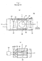
- Fig.1 is a view of a structure for an optical pick-up actuator of a related art.
- the optical pick-up actuator of a related art is of a structure such that an object lens 101 is mounted on a lens holder 102, a focusing coil 105 for performing focusing being attached on a periphery of the lens holder 102, a tracking coil 106 wired in an appropriate direction, for performing tracking being attached on each corner section.
- a permanent magnet 103 is fixed on the inner surface of an U-shaped yoke 104 which is a member of ferromagnetic material positioned on right and left of the lens holder 102, and the yoke 104 is integrally formed together with a pick-up base(not shown) by integrating means.
- a fixing unit 108 is joined to the central part on the lateral side of the upper and the lower part of such lens holder 102, one end of two parallel wire suspensions 107 being fixed in each of the fixing units 108, and the other end of the wire suspension 107 being fixed in a main PCB through a frame 109 prepared on one side of the lens holder 102.
- a damper (not shown) is joined in the inside of the frame 109 so that the wire suspension 107 having rigid property may have attenuation characteristics and a main PCB (not shown) is joined in the outside of the frame so that the other end of the wire suspension 107 may be fixed in a soldering manner.
- Such wire suspension 107 raises the lens holder 102, playing a role of supplying a current as a relay line.
- a focusing coil 105 is wired in vertical direction unlike a tracking coil, so that magnetic flux is generated in up and down direction upon flowing of a current i, interacting with magnetic flux of a fixed magnet 103, whereby force is generated, in vertical direction, at the focusing coil 105. Thanks to such vertical force, the lens holder 102 is moved in a focusing direction(vertically up and down) and a focusing servo operates for correcting a focusing error.
- the tracking coils 106 attached on the lens holder 102 are appropriately wired each other, for generating magnetic flux in a predetermined direction upon flowing of a current, interacting with magnetic force of the fixed magnet 103, whereby repulsive force is generated. Thanks to such repulsive force, the lens holder 102 is moved in tracking direction (right and left), whereby a tracking servo operates for correcting a tracking error.
- a type such that a magnet is attached on the outer periphery of the lens holder 102 and moved together with the lens holder 102 is referred to as a moving magnet type.
- movement types by the magnet and the coil make use of Lorenz force by Fleming's left-hand rule.
- Such optical pick-up actuator 100 moves using coils operable by magnetic field of permanent magnet, whereby an object lens is moved to a predetermined desired position on an optical recording medium.
- the lens holder which is a moving part of the optical pick-up actuator, is fixed by the wire suspension having rigid property and attenuation characteristics, so that a predetermined frequency characteristics is provided.
- the lens holder performs a translational motion in the focusing and the tracking directions which are two mutually perpendicular directions, and motion should be performed without unnecessary vibration such as rotation and twisting.
- a width of a track itself and an interval between tracks are useful so that data could be sequentially and sufficiently accessed by only movements of the pick-up itself and the lens of the actuator, but in a disk format of high density, data could not be exactly accessed by the actuator of a related art.
- a tilt component needs to be corrected so that a laser beam reflected through the reflecting mirror 111 may be exactly projected to a reflection plane of an optical disk 110 by an object lens 101.
- the actuator should operates in a tilting motion mode in radial direction as well as the translational motions in the tracking and the focusing directions. According to the structure of a related art, however, operation to the tilting motion mode is not possible.
- An object of the invention is to solve at least the above problems and/or disadvantages and to provide an optical pick-up actuator operable in multiple axes.
- one object of the present invention is to solve the foregoing problems by providing an optical pick-up actuator such that a magnetic circuit is prepared by a plurality of coils connected in series/paxallel in each of both sides of a moving part and a polarity generating means where different polazities are perpendicular each other, and moving the lens holder to the tracking, the focusing, and the radical directions using the magnetic circuit is possibly performed.
- Another object of the present invention is to provide an optical pick-up actuator having a magnetic circuit such that coils on the central portion on both sides of the moving part are series connected and faced with a boundary surface between different polarities, for tracking movement, and coils on right/left in both sides of the lens holder are parallel connected and faced with a boundary surface between different polarities, for moving in focusing/radial tilting direction among a plurality of the coils.
- Another object of the invention is to provide an optical pick-up actuator capable of improving movement force of the focusing coil, the tracking coil and the tilting coil prepared in the corresponding position due to effect of the magnet having multiple poles, by arranging the magnet having multiple poles and magnetic yoke so that magnetic flux generated from magnetic material having different poles constitutes a closed circuit.
- an optical pick-up actuator including: a lens holder for receiving and moving an object lens in a predetermined direction; a plurality of first coils parallel connected on one side of both sides of the lens holder, for focusing and tilting movement of the lens holder; a single second coil attached on a central portion in both sides of the lens holder, for tracking movement of the lens holder; and a polarity generating means faced with the first and the second coils, for generating different polarity in perpendicular directions.
- Fig. 1 is a plan view and a sided view of an optical pick-up actuator of a related art
- Fig.2 is a view showing operation status of a magnetic circuit of an optical pick-up actuator of a related art
- Fig.3 is a view showing tilt correction for a disk according to an actuator
- Fig.4 is a plan view of an optical pick-up actuator according to an embodiment of the present invention.
- Fig.5 is a view showing application status of wire type coil according to an embodiment of the present invention.
- Fig.6 is a view showing application status of a fine pattern coil according to an embodiment of the present invention.
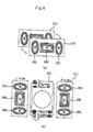
- Fig.7 is a view showing magnetic circuit construction of an optical pick-up actuator according to a first embodiment of the present invention.
- Fig.8 is a view showing movement status to the tracking, focusing, tilting directions by a magnetic circuit of Fig.7;
- Fig.9 is a view showing another example for a shape of a fine pattern coil according to the present invention.
- Fig.10 is a view showing a magnetic circuit construction of an optical pick-up actuator according to a second embodiment of the present invention.
- Fig.11 is a view showing movement status to the tracking, the focusing, the tilting directions by a magnetic circuit construction of Fig.10;
- Fig.12 is a view showing a magnetic circuit construction of an optical pick-up actuator according to a third embodiment of the present invention.
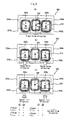
- Fig.13 is a view showing a magnetic circuit construction of an optical pick-up actuator according to a fourth embodiment of the present invention.
- Fig.14 is a view showing an example of movement status to the tracking, the focusing, the tilting directions by a magnetic circuit of Fig.13;
- Fig.15 is a view showing another example of movement status to the tracking, the focusing, the tilting directions by a magnetic circuit of Fig.13;
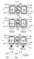
- Fig.16 is a view showing a magnetic circuit construction of an optical pick-up actuator according to a fifth embodiment of the present invention.
- Fig.17 is a view showing movement status to the tracking, the focusing, the tilting directions by a magnetic circuit of Fig.14;
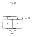
- Fig.18 is a view of construction showing another example of four polarities according to the present invention.
- Fig.19 through Fig.22 are a schematic view applying a wire type coil to a magnetic circuit according to an embodiment of the present invention and a view showing magnetic field distribution of a magnet;
- Fig.23 is a view showing the tracking, the focusing movement status by a magnetic circuit of Fig.22;
- Fig.24 is a view showing movement status to the tracking, the focusing, the tilting directions by a magnetic circuit of Fig.22;
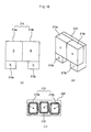
- Fig.25 is a view of construction showing another embodiment of an optical pick-up actuator according to the present invention.
- Fig.26 is a view of a magnetic circuit construction of Fig.25 of the present invention.
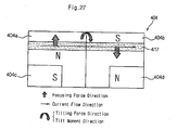
- Fig.27 is a view showing tilting movement status in a magnetic circuit of Fig.26.
- the present invention provides a magnetic circuit for moving a lens holder of an optical pick-up actuator in the tracking, the focusing, and the radial tiling directions
- the magnetic circuit includes a magnet and a polarity auxiliary means whose polarity is induced so that different polarity are prepared in perpendicular direction and a center of coil movement is faced with a boundary surface between the different polarities.
- a polarity auxiliary means instead of a polarity auxiliary means, one single magnet having multiple poles or a plurality of single pole magnets may be used in order to generate at least more than four polarities, and the coil faced with the boundary surface between the polarities may be prepared, so that the lens holder could be moved
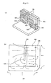
- Fig.4 is a plan view of an optical pick-up actuator according to the present invention.
- an optical pick-up actuator of the present invention includes: a lens holder 202 having an object lens 201 on its central portion; an U-shaped yoke 203 projected from a yoke 204 of a pick-up base; a magnet 204 having multiple poles, attached on an inside of the U-shaped yoke 203; a plurality of first coils 205 attached on right/left in both sides of the lens holder 202 for being faced with the magnet 204, and a second coil 206 attached on a central portion of the lens holder 202; a pair of wire suspensions 207 for connecting and supporting a fixing unit 208 on a lateral end of the lens holder 202 and a fixed frame 209; and a main PCB 211 attached on a back of the wire suspension 207.
- the first coils 205 are focusing/tilting coils such that a plurality of coils is parallel connected and different polarities are faced with each other in vertical direction, and movement in the focusing or the tilting directions is controlled by making directions(+,-) of a current applied to the first coils 205 same or different each other.
- the second coil 206 is a tracking coil such that different polarities of the magnet 204 are faced with in horizontal direction, so that the lens holder is moved in the tracking direction depending on directions(+,-) and intensity of a current.
- the first coils and the second coil 205 and 206 may be installed independently on both sides of the lens holder, respectively, or on one single substrate in form of a printed status.
- the first coils and the second coil 205 and 206 may be fixed by a manner of a wire type coil where the first coils and the second coil are wired respectively and attached on the lens holder with being fixed by a bobbin(not shown), or as shown in Fig.6 (a) and (b), the first coils and the second coil may be installed by being printed on a fine pattern coil PCB 210 in form of fine pattern(FP).
- the coils are formed in a rectangular shape so that big movement force could be generated.
- first coils 205 and the second coil 206 are provided with a current from the wire suspension 207 connected, in pairs(two or three), on each lateral side of the lens holder.
- the optical pick-up actuator mounts the object lens 202 on the central portion of the lens holder 202, constituting a magnetic circuit using a pair of the first coils 205 parallel connected on both lateral sides, one single second coil 206, the yoke 203 and the magnet 204.
- the coils 205 and 206 arc installed respectively in form of the wire type coil or the fine pattern type coil PCB on which coils are wired in a fine pattern.
- the magnet having multiple poles, a plurality of single pole magnets, combination of a plurality of magnetic yokes may be used in order to generate at least four polarities.
- Such lens holder 201 is supported by the wire suspension 207 under the influence of electromagnetic force generated from the magnetic circuit and moved in the tracking, the focusing, and the tilting directions.
- Fig.7 and Fig.8 show the first embodiment of the present invention.
- the first embodiment includes: a magnet 204(204a, 204b) having multiple poles of different polarities; a plurality of magnetic yokes 203a and 203b; and a plurality of coils 205a, 205b, 206.
- description will be made with the reference numerals 204a and 204b given to the first magnet and the second magnet, respectively, depending on polarity of the magnet 204.
- the magnet 204(204a and 204b) having multiple poles in a symmetric shape is attached horizontally on the yoke body 203, and the magnetic yokes 203a and 203b projected right/left from the yoke body 203 are formed on one end in the lower portion of the magnet 204, respectively.
- a plurality of single pole magnets may be used instead of the magnet having two poles.
- a polarity opposite to the polarity of the first magnet 204a on the upper end is induced at the first magnetic yoke 203a
- a polarity opposite to the polarity of the second magnet 204b on the upper end is induced at the second magnetic yoke 203b.
- the magnetic yokes 203a and 203b are integrally formed on the yoke body 203.
- magnets 204(204a and 204b) and the magnetic yokes 203a and 203b From and to such magnets 204(204a and 204b) and the magnetic yokes 203a and 203b, magnetic flux that is perpendicular in horizontal and vertical directions, diverges and converges.
- the polarities of the magnets may be made opposite.
- the magnet 204(204a and 204b) having multiple poles and the magnetic yokes 203a and 203b are faced with the first coils and the second coil 205 and 206, whereby the magnetic circuit could be prepared.
- the first coils 205 are parallel connected each other in their right/left sides, and a center of movement of each coil 205a and 205b is positioned on a boundary between the magnets 204a and 204b in vertical direction, and a boundary between the magnetic yokes 203a and 203b, namely, a boundary between polarities, while a center of movement of the second coil 206 is positioned on a boundary between the first and the second magnets 204a, 204b having different polarities.
- the first and the second coils may be used in form of the wire type coil or in a status printed on the fine pattern coil PCB 220.
- directions of the focusing movement force and tilting movement force could be controlled by polarities of the magnets 204a and 204b, induced polarities of the magnetic yokes 203a and 203b, and directions of the current flowing in the first coils 205a and 205b parallel connected, whereby focusing servo and tilting servo for recording medium could be performed.
- direction of the tracking movement force could be controlled by direction of a current flowing in the second coil 206 prepared in the boundary between polarities of the magnets 204a and 204b, whereby tracking servo for recording medium could be performed.
- magnetic field flux of a closed circuit is formed with use of the magnet 204 having multiple poles and a plurality of magnetic yokes 203a and 203b, and the focusing/tilting coils and tracking coil are mounted on the position where the formed magnetic field flux could be effectively used, whereby the focusing movement force, die tilting movement force and the tracking movement force could be improved.
- magnet 204 having multiple poles instead of the magnet 204 having multiple poles used in the above, a plurality of single pole magnets may be used.
- Fig.9 is a view showing a status that coils are formed on the PCB 210.
- Wiring shape of the second coil 206 may be formed in a rhombic shape or an egg shape, and the first coils 205 may be printed, by a fine pattern, in a shape corresponding to the wiring shape of the second coil 206.
- Fig.10 and Fig.11 show the second embodiment of the present invention.
- the magnetic circuit includes: a magnet 214(214a, 214b) having multiple poles; two magnetic yokes 213a and 213b; and a plurality of coils 215a, 215b, 216.
- description will be made with the reference numerals 214a and 214b given to the first magnet and the second magnet, respectively, depending on polarity of the magnet 214.
- a plurality of magnets 214(214a and 214b) of a rectangular shape horizontally arranged and attached on the yoke body 213, and a first and a second magnetic yokes 213a and 213b projected from the yoke body 213 on each of lower portions of the magnets 214 are provided, and the first and the second yokes 213a and 213b have induced polarities opposite to the polarities of the magnets 214.
- the magnet instead of the magnet having multiple poles and the magnetic yokes, two or four single pole magnets may be used.
- first coils 215(215a and 215b) arc printed on the left/right sides of a fine pattern PCB, and a second coil 216 is arranged on the center.
- a center of movement of the first coil 215a on the left is faced with a boundary between the first magnet 214a and the first magnetic yoke 213a
- a center of movement of the first coil 215b on the right is faced with a boundary between the second magnet 214b and the second magnetic yoke 213b
- a center of movement of the second coil 216 is faced with a boundary between the first and the second magnets 214a, 214b.
- the first coils and the second coil may be used in a printed form on a fine pattern coil PCB 220 or independently used in form of a wire type coil.
- Fig.11 (a),(b),(c) show controlling of the tracking, the focusing, and the tilting movements by the magnetic circuit as shown in Fig.10.
- Fig.11 operates in the same way as Fig.8. Therefore, detailed description thereof will be omitted.
- Fig.12 shows the third embodiment of the present invention.
- the magnetic cizcuit includes: a magnet 224(224a, 224b, 224c, 224d) having multiple poles; and coils 225a, 225b, 226.
- description will be made with the reference numerals 224a, 224b, 224c, 224d given to the first, the second, the third, the fourth magnets, respectively, depending on polarity of the magnet 224.
- the first and the second magnets 224a and 224b symmetric in a shape, and the third and the fourth magnets 224c and 224d having opposite polarities on the lower end of the first and the second magnets 224a and 224b, are integrally attached to the yoke body 223. Accordingly, S and N poles of the first and the second magnets 224a and 224b are positioned in vertical direction, while S and N poles of the first and the third magnets 224a and 224c are positioned on the left column in vertical direction, and N and S poles of the second and the fourth magnets 224b and 224d are positioned on the right column in vertical direction.
- two magnets having two poles or four single pole magnets may be used.
- the first coil 225a on the left is faced with a boundary between the first and the third magnets
- the first coil 225b on the right is faced with a boundary between the second and the fourth magnets
- the second coil 226 on the center is faced with a boundary between the first and the second magnets.
- the first and the second coils may be used in a printed form on a fine pattern coil PCB 230 or independently attached in form of a wire type coil.
- Such magnetic circuit according to the third embodiment of the present invention is the same as the magnetic circuit in Fig.11, so that detailed description thereof will be omitted, and the lens holder is moved in the tracking, the focusing and the tilting directions.
- the magnetic circuit has been prepared with use of four polarities and three pairs of coils, but a magnetic circuit having six polarities and corresponding coil structure will be described in the following.
- Fig.13 through Fig.15 show the fourth embodiment of the present invention.
- the magnetic circuit includes: a magnet 234(234a, 234b) having multiple poles; a plurality of magnetic yokes 233a, 233b from which different polarities are induced; and coils 235a through 235d.
- description will be made with the reference numerals 234a, 234b given to the first and the second magnets, respectively, depending on polarity of the magnet 234.
- two single pole magnets may be used instead of the magnet having multiple poles.
- the magnetic circuit is configured such that the magnet 234(234a, 234b) having two poles(S and N) is fixed on the center of the yoke body 233 and the first and the second magnetic yokes 233a and 233b are projected, with the same width, on the upper/lower end of the first and the second magnets 234a and 234b. Accordingly, the first and the second magnetic yokes 233a and 233b have induced polarities, respectively, opposite to the polarities of the first and the second magnets 234a and 234b on the center.
- the polarities of the first and the second magnets 234a and 234b are N and S, respectively, the polarities of the first magnetic yoke 233a on the upper end are induced into S and N, and the polarities of the second magnetic yoke 233b on the lower end are induced into S and N.
- the polarities of the magnetic yokes change depending on polarities of the magnets.
- the polarities of the magnet 234 are represented as two columns S:N:S and N:S:N in vertical direction. Namely, the left column is arranged in the order of S of the first magnetic yoke, N of the first magnet, and S of the second magnetic yoke, while the right column is arranged in the order of N of the first magnetic yoke, S of the second magnet, and N of the second magnetic yoke.
- the coils of the magnetic circuit is configured such that a pair of 1a coils 235a and 235b on the left/right in the upper portion, a pair of 1b coils 235c and 235d on the left/right in the lower portion, the second coil 236 on the center, are formed.
- the 1a and 1b coils 235a through 235d are faced with boundaries between the magnets 234a, 234b and the magnetic yokes 233a, 233b, and the second coil 236 is faced with a boundary between polarities of the magnets 234a and 234b.
- Fig.14 shows an embodiment for movement control by construction of the magnetic circuit as shown in Fig.13.
- the 1a coils 235a and 235b positioned on the left/right in the upper portion are series connected each other, and the 1b coils 235c and 235d positioned on the left/right in the lower portion are series connected each other.
- the focusing movement is determined through control of direction and intensity of a current applied to the 1a coils 235a and 235b on the upper portion
- the tilting movement is determined through control of direction and intensity of a current applied to the 1b coils 235c and 235d on the lower portion.
- the left/right of the 1b coils 235c and 235d are wired in the opposite directions each other for control of the radial tilt
- the tracking movement is determined through control of direction and intensity of a current applied to the second coil 236 positioned on a boundary between the first and the second magnets 234a, 234b.
- the magnetic circuit may be formed by separation of the focusing coil, the tilting coil and the tracking coil.
- a current for the focusing movement upon application of a current for the focusing movement, to 1 ⁇ ,2 ⁇ of the 1a coil, a current of the same direction is applied to 3 ⁇ ,4 ⁇ of the 1b coil, so that focusing movement force could be improved.
- Fig.15 shows another embodiment for movement control by construction of the magnetic circuit as shown in Fig.13.
- Fig.15 (a) is a view showing a status of the tracking movement
- Fig.15 (b) shows a status of the focusing movement If directions and intensities of currents are equally controlled with respect to the right/left of the 1a and the 1b coils 235a through 235d, the coils on the right/left all are moved to the focusing direction by electromagnetic force generated between the magnets 234a, 234b and the magnetic yokes 233a, 233b faced with the coils 235a through 235d.
- Fig.15 (c) shows a status of the tilting movement. If directions of currents applied to the coils 235a and 235c on the left and the coils 235b and 235d on the right, are reversed with same intensity, then the movement to the radial tilting direction is controlled. Namely, the left of the lens holder is moved to the down direction and the right of the lens holder is moved to the up direction.
- the magnetic circuit of Fig.15 is configured such that 1 ⁇ /2 ⁇ and 3 ⁇ /4 ⁇ of the first coils are series connected, respectively, and the same current is applied to 1 ⁇ /2 ⁇ coils and 3 ⁇ /4 ⁇ coils, respectively, for the focusing movement, and currents of different directions are applied to 1 ⁇ /2 ⁇ coils and 3 ⁇ /4 ⁇ coils of the first coils, respectively, for the tilting movement
- Fig.16 and Fig.17 show the fifth embodiment of the present invention.
- the magnetic circuit includes: a magnet 244(244a through 244d) having four poles; and a pair of the first coils 245(245a and 245b) and the second coils 246(246a and 246b) faced with a boundary between polarities.
- description will be made with the reference numerals 244a, 244b, 244c, 244d given to the first, the second, the third, the fourth magnets, respectively, depending on polarity of the magnet 244 having four poles.
- the magnet 244(244a through 244d) having four poles is fixed on the front of the yoke body 243.
- the first coils 245(245a and 245b) on the left/right in both sides of the lens holder, are faced with a boundary between polarities of the first and the third magnets 244a, 244c, and faced with a boundary between polarities of the second and the fourth magnets 244b, 244d vertically arranged, and are moved to the focusing/tilting directions.
- the second coils 246(246a and 246b) on the up/down of the center in both sides of the lens holder are respectively faced with boundaries between polarities of the magnets 244a, 244b, and 244c, 244d, and are moved to the tracking direction.
- the magnet instead of the magnet having four poles, four single pole magnets or two magnets having two poles may be used.
- the coils may be used in form of a wire type coil or in a printed form on a fine pattern coil PCB 250.
- Fig.17 shows an embodiment for movement control by construction of the magnetic circuit as shown in Fig.16. Operation of the magnetic circuit will be described in the following.
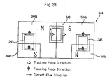
- Fig.17 (a) shows a status for the tracking movement. If a current of the same direction is applied to the second coils 246a and 246b, the lens holder is moved to the tracking direction by different polarities of the magnets 244a through 244d.
- Fig.17 (b) shows a status for the focusing movement. If the first coils on the right/left are controlled by a current of the same direction and intensity, the lens holder is moved to the focusing direction by electromagnetic forces generated between the first and the third magnets 244a, 244c, and between the second and the fourth magnets 244b, 244d faced with the first coils 245a and 245b.
- Fig.17 (c) shows a status for the tilting movement If the coils 245a and 245b on the left/right are controlled by currents of opposite directions with the same intensity, the lens holder is moved to the tilting directions by electromagnetic forces generated between the magnets 244a. and 244c and between the magnets 244b and 244d faced with the first coils 245a and 245b.
- the direction of the tracking movement force is controlled by the direction flowing in the second coils 246a and 246b positioned on a boundary between single pole magnets 244 on the left and the right columns, and polarity arrangement of the single pole magnets 244, whereby tracking servo for recording medium could be performed.
- magnetic field flux of a dosed circuit is formed with use of a plurality of the single magnets 244 having different pole, and the focusing/tilting coils and tracking coil are mounted on the position where the formed magnetic field flux could be effectively used, whereby the focusing movement force, the tilting movement force and the tracking movement force could be improved.
- Fig.18 shows an example of a polarity generating means for the magnetic circuit. It is another embodiment of four polarities, in which a magnet having two poles or a plurality of single pole magnets is formed, and a magnetic yoke 253 having the same width as the above magnet and from which opposite polarities are induced, is formed.
- Fig.19 and Fig.22 are drawings showing magnetic field distribution for the wire type coil and polarity.
- Fig.19 shows the first embodiment applying the wire type coil.
- the magnetic circuit includes: two single pole magnets 304 or one magnet having two poles on the front of the yoke body 303; a pair of first coils 305 on the right/left, faced with the single pole magnet in vertical direction; and the second coil 306 on the center, faced with the boundary between polarities in horizontal direction.
- the magnetic flux has characteristic distribution diverging from N pole and converging into S pole and the yoke body.
- Fig.20 shows the second embodiment applying the wire type coil.
- Fig.20 (a) is the same as the magnetic circuit in Fig.7 in its construction, so that detailed description thereof will be omitted. Namely, if opposite polarities S and N are induced at two magnetic yokes 313a and 313b, respectively, by the magnet 314 having two poles N and S or one magnet having two poles, then four polarities are generated, so that the magnetic field flux, as shown in Fig.20 (b), diverges from N pole, converging into S pole, thereby constituting a closed circuit
- Fig.21 and Fig.22 show the third and the fourth embodiments applying the wire type coil.
- Fig.21 (a) and Fig.22 (a) show construction of the magnetic circuit including: the magnet 324 having four poles; a pair of first coils 325 on the right/left, faced with the magnet; and the second coil 326 on the center.
- Fig.21 (b) and Fig.22 (b) are drawings showing magnetic field distributions due to the magnet having four poles.
- the magnet having four poles instead of the magnet having four poles, four single pole magnets or two magnets having two poles may be used.
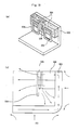
- Fig.23 is another embodiment of the present invention, showing the magnetic circuit of two axes where the tracking and the focusing movements are possibly performed with use of three pairs of coils 345 and 346 faced with the magnets 344(344a through 344d) having four poles.
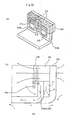
- Fig.24 is further another embodiment of the present invention, showing the magnetic circuit of three axes where the tracking, the focusing and the tilting movements are possibly performed with use of three pairs of coils 345 and 346 faced with the magnets 344 having four poles.
- All the embodiments (the first through the fourth embodiments) described in the foregoing, relates to the actuator of three axes for the focusing, the tracking, and the tilting movements. If the actuator of two axes of the related art for the focusing and the tracking movements without the tilting movement, is used for application, a pair of the focusing coils on the right/left parallel connected, is all simply series connected, so that the same current flows and usage for only the focusing movement may be possible. Therefore, the actuator could be used as the actuator of two axes together with the tracking movement of the related art. As operation thereof would be understood from descriptions of each embodiment in the above, detailed description will be omitted.
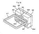
- Fig.25 through Fig.27 show still further another embodiment of the present invention.
- the magnetic circuit for the tracking and the focusing movement is formed by the magnet 404(404a through 404d) having multiple poles, or four single pole magnets, or two magnets having two poles, faced with the coils 405 and 406 on both sides of the lens holder, and the magnetic circuit for the radial tilting movement is formed by the magnets 404a and 404b, and the third coil 417 wired on the outer periphery of the lens holder 402.
- description will be made with the reference numerals 404a, 404b, 404c, 404d given to the first, the second, the third, the fourth magnets, respectively, depending on polarity of the magnet 404.
- the first coils 405 are faced with the boundaries between polarities of the magnets 404a, 404c and 404b, 404d having different polarities, which are vertically arranged on the left and right sides
- the second coil 406 is faced with the boundary between polarities of the first and the second magnets 404a, 404b having different polarities, which are horizontally arranged on the center
- the third coil 417 is horizontally wired and faced with the boundary between polarities of the first and the second magnets 404a, 404b which are horizontally arranged.
- the first coil 405 is moved to the up/down directions vertically under the influence of electromagnetic force generated between the first and the third magnets 404a, 404c, and between the second and the fourth magnets 404b, 404d which are vertically different in their polarities, while the second coil 406 is moved to the right/left directions horizontally under the influence of electromagnetic force generated between the first and the second magnets 404a, 404b which are horizontally different in their polarities.
- the third coil 417 is the radial tilting coil If a current of a predetermined direction, is applied to the third coil 417, the left and the right of the third coil 417 are moved to the vertically opposite directions, respectively, under the influence of electromagnetic force generated between the first and the second magnets 404a, 404b which are horizontally different in their polarities, so that the radial tilting movement is performed.
- At least two or three wire suspensions 407 could be connected to the center on the right/left of the lens holder in order to provide a current to the coils 405 and 417.
- three coils on both sides of the lens holder are faced with perpendicularly different polarities, so that control of three axes including the tracking, the focusing, and the tilting movements, is possibly performed.
- a perpendicular polarity generating means one single magnet having multiple poles, or a plurality of single pole magnets, or combination of magnetic yokes whose opposite polarities are induced from one side of the magnet, could be used. Also, at least four polarities are provided as perpendicularly different polarities.
- the coils could be used in form of the wire type coil or in a printed form on the PCB of the fine pattern coil shape.
- a type using the separate tilting coil according to an embodiment in Fig.26 could be used for the actuator for the focusing, the tracking, and the tilting movements like all the above embodiments(the first-the fifth embodiments).
- a pair of the coils on the right/left parallel connected is all series connected so that the same current may flow and only the focusing movement is possibly performed, for the tilting movement is no more needed.
- operation method thereof would be understood from descriptions of embodiments in the above, detailed description will be omitted.
- the present invention realizes effects due to the magnet having multiple poles, by constituting a closed circuit using magnetic flux generated from the magnet having multiple poles, or by obtaining multiple polarities using the single pole magnets and the magnetic yokes, whereby movement forces of the focusing, the tracking, and the tilting coils prepared on the relevant position are possibly improved.
Landscapes
- Optical Recording Or Reproduction (AREA)
Applications Claiming Priority (4)
| Application Number | Priority Date | Filing Date | Title |
|---|---|---|---|
| KR2002021747 | 2002-04-20 | ||
| KR10-2002-0021747A KR100488039B1 (ko) | 2002-04-20 | 2002-04-20 | 광픽업 액츄에이터 |
| KR2002048957 | 2002-08-19 | ||
| KR10-2002-0048957A KR100479617B1 (ko) | 2002-08-19 | 2002-08-19 | 광픽업 액츄에이터 |
Publications (2)
| Publication Number | Publication Date |
|---|---|
| EP1355301A2 true EP1355301A2 (de) | 2003-10-22 |
| EP1355301A3 EP1355301A3 (de) | 2006-03-29 |
Family
ID=28677695
Family Applications (1)
| Application Number | Title | Priority Date | Filing Date |
|---|---|---|---|
| EP03009076A Withdrawn EP1355301A3 (de) | 2002-04-20 | 2003-04-18 | Aktuator für optisches Abtastgerät |
Country Status (3)
| Country | Link |
|---|---|
| US (1) | US7385885B2 (de) |
| EP (1) | EP1355301A3 (de) |
| CN (1) | CN1312676C (de) |
Cited By (8)
| Publication number | Priority date | Publication date | Assignee | Title |
|---|---|---|---|---|
| EP1544853A3 (de) * | 2003-12-17 | 2006-05-24 | Samsung Electronics Co., Ltd. | Magnetkreisanordnung und damit versehenes optisches Aufzeichnungs- und/oder Wiedergabegerät |
| EP1605447A3 (de) * | 2004-06-10 | 2006-07-05 | Samsung Electronics Co., Ltd. | Optisches Plattengerät mit der Fähigkeit zur Neigungskompensation eines optischen Abtastgeräts, und Neigungskompensationsverfahren |
| DE102005000909A1 (de) * | 2005-01-06 | 2006-07-20 | Deutsche Thomson-Brandt Gmbh | Optische Abtastvorrichtung für Geräte zur Aufzeichung oder Wiedergabe von Informationen mit einem optischen Aufzeichnungsträger |
| EP1612780A3 (de) * | 2004-06-25 | 2006-08-02 | Lg Electronics Inc. | Antrieb für einen optischen Abtastkopf |
| EP1724766A1 (de) * | 2005-05-18 | 2006-11-22 | Deutsche Thomson-Brandt Gmbh | Abtasteinrichtung für optische Aufzeichnungsträger und Gerät mit dieser Abtasteinrichtung |
| EP1560207A3 (de) * | 2004-01-27 | 2006-12-06 | Samsung Electronics Co., Ltd. | Magnetischer Kreis und Stellantrieb für optisches Abtastgerät und optisches Aufzeichnungs- und/oder Wiedergabegerät das diesen Stellantrieb verwendet |
| WO2007072333A1 (en) * | 2005-12-21 | 2007-06-28 | Koninklijke Philips Electronics N.V. | Optical pickup actuator and optical scanning device |
| EP2136365A1 (de) * | 2003-11-13 | 2009-12-23 | Samsung Electronics Co., Ltd. | Hochempfindlicher Lesekopf für ein Laufwerk |
Families Citing this family (19)
| Publication number | Priority date | Publication date | Assignee | Title |
|---|---|---|---|---|
| KR100522594B1 (ko) * | 2002-10-25 | 2005-10-24 | 삼성전자주식회사 | 호환형 광픽업장치 및 이를 채용한 광기록재생장치 |
| KR100486285B1 (ko) * | 2002-11-26 | 2005-04-29 | 삼성전자주식회사 | 광픽업 액츄에이터 및 이를 채용한 광 기록 및/또는재생기기 |
| JP3095448U (ja) * | 2003-01-23 | 2003-07-31 | 船井電機株式会社 | 光ピックアップ |
| KR100547360B1 (ko) * | 2003-09-16 | 2006-01-26 | 삼성전기주식회사 | 권선 코일이 일체화된 보빈, 이를 채용한 광픽업액추에이터 및 그 제조 방법 |
| JP2006066048A (ja) * | 2003-12-25 | 2006-03-09 | Nidec Sankyo Corp | 対物レンズ駆動装置、及びそれを備えた光ヘッド装置 |
| KR100555657B1 (ko) * | 2004-05-28 | 2006-03-03 | 삼성전자주식회사 | 광픽업용 액츄에이터 |
| DE602005008647D1 (de) * | 2004-12-09 | 2008-09-11 | Thomson Licensing Sa | Aktor für einen optischen scanner |
| US7408848B2 (en) * | 2004-12-28 | 2008-08-05 | Industrial Technology Research Institute | Objective lens actuator |
| JP2006286049A (ja) * | 2005-03-31 | 2006-10-19 | Toshiba Corp | 光ディスク装置 |
| CN100428345C (zh) * | 2005-04-15 | 2008-10-22 | 清华大学 | 倾斜驱动方式的三维物镜驱动装置 |
| TW200709200A (en) * | 2005-08-29 | 2007-03-01 | Lite On It Corp | Actuator of optical pickup head with horizontal-arranged magnetic field generator and coil apparatus |
| EP1783758A1 (de) * | 2005-11-07 | 2007-05-09 | Deutsche Thomson-Brandt Gmbh | Antriebsvorrichtung einer Objektivlinse für optische Aufzeichnungsträger und Gerät mit einer solcher Antriebsvorrichtung |
| TWI322424B (en) * | 2005-12-27 | 2010-03-21 | Ind Tech Res Inst | Objective lens deiving apparatus |
| EP1914763B1 (de) * | 2006-10-17 | 2013-01-09 | Harman Becker Automotive Systems GmbH | Leiterplatte mit gedruckten Wicklungen |
| JP4666236B2 (ja) * | 2008-06-09 | 2011-04-06 | ソニー株式会社 | 光ピックアップ及びディスクドライブ装置 |
| JP2013069389A (ja) * | 2011-09-26 | 2013-04-18 | Sanyo Electric Co Ltd | 対物レンズ駆動装置およびそれを備えた光ピックアップ装置 |
| US8817116B2 (en) | 2011-10-28 | 2014-08-26 | Lg Innotek Co., Ltd. | Camera module |
| CN102722064A (zh) * | 2012-06-01 | 2012-10-10 | 深圳市立博电子有限公司 | 滤光片切换器 |
| US10935752B2 (en) * | 2016-07-21 | 2021-03-02 | Lg Innotek Co., Ltd. | Lens driving device, and camera module and optical device, which include same |
Family Cites Families (17)
| Publication number | Priority date | Publication date | Assignee | Title |
|---|---|---|---|---|
| JPS63257927A (ja) * | 1987-04-15 | 1988-10-25 | Pioneer Electronic Corp | ピツクアツプアクチユエ−タ |
| JPH04366429A (ja) * | 1991-06-14 | 1992-12-18 | Toshiba Corp | 対物レンズ駆動装置 |
| JP3246140B2 (ja) * | 1993-11-16 | 2002-01-15 | ソニー株式会社 | 対物レンズ駆動装置 |
| US5663840A (en) * | 1994-06-14 | 1997-09-02 | Nec Corporation | Objective lens actuator for optical head and used for high speed access |
| JP2760307B2 (ja) | 1995-03-30 | 1998-05-28 | 日本電気株式会社 | 光ヘッドの対物レンズアクチュエータ |
| US5986983A (en) * | 1997-11-19 | 1999-11-16 | Eastman Kodak Company | Multiple degrees of freedom actuator for optical recording |
| SG72954A1 (en) | 1998-05-21 | 2000-05-23 | Samsung Electronics Co Ltd | Optical pickup |
| US6343053B1 (en) * | 1998-08-28 | 2002-01-29 | Ricoh Company, Ltd. | Objective lens driving apparatus for driving an objective lens of an optical disk drive |
| US6344936B1 (en) * | 1999-09-29 | 2002-02-05 | Matsushita Electric Industrial Co., Ltd. | Objective lens driving apparatus |
| JP2001155358A (ja) * | 1999-11-24 | 2001-06-08 | Nec Corp | 対物レンズ駆動装置 |
| TW522394B (en) * | 2000-07-14 | 2003-03-01 | Tdk Corp | Objective lens drive apparatus for use in optical pickup |
| JP3875522B2 (ja) * | 2000-07-14 | 2007-01-31 | Tdk株式会社 | 光ピックアップの対物レンズ駆動装置 |
| CN1355613A (zh) | 2000-11-25 | 2002-06-26 | 郑禄 | 无线公共电话装置 |
| KR100727911B1 (ko) * | 2000-12-08 | 2007-06-14 | 삼성전자주식회사 | 광픽업용 4축구동 액추에이터 |
| KR100421042B1 (ko) * | 2001-06-19 | 2004-03-04 | 삼성전자주식회사 | 광픽업 액튜에이터 구동 방법 및 광픽업 액튜에이터 |
| KR100421041B1 (ko) * | 2001-06-19 | 2004-03-04 | 삼성전자주식회사 | 광픽업 액튜에이터, 광픽업 장치 및 광기록/재생 장치 |
| JP2003196870A (ja) * | 2001-12-26 | 2003-07-11 | Tdk Corp | 光ディスクドライブ装置、光ピックアップ及びこれらの製造方法、調整方法 |
-
2003
- 2003-04-18 EP EP03009076A patent/EP1355301A3/de not_active Withdrawn
- 2003-04-21 CN CNB031225780A patent/CN1312676C/zh not_active Expired - Fee Related
- 2003-04-21 US US10/419,533 patent/US7385885B2/en not_active Expired - Lifetime
Non-Patent Citations (1)
| Title |
|---|
| None * |
Cited By (12)
| Publication number | Priority date | Publication date | Assignee | Title |
|---|---|---|---|---|
| EP2136365A1 (de) * | 2003-11-13 | 2009-12-23 | Samsung Electronics Co., Ltd. | Hochempfindlicher Lesekopf für ein Laufwerk |
| EP1544853A3 (de) * | 2003-12-17 | 2006-05-24 | Samsung Electronics Co., Ltd. | Magnetkreisanordnung und damit versehenes optisches Aufzeichnungs- und/oder Wiedergabegerät |
| US8018800B2 (en) | 2003-12-17 | 2011-09-13 | Samsung Electronics Co., Ltd. | Optical recording and/or reproducing apparatus having a high-sensitivity magnetic circuit |
| EP1560207A3 (de) * | 2004-01-27 | 2006-12-06 | Samsung Electronics Co., Ltd. | Magnetischer Kreis und Stellantrieb für optisches Abtastgerät und optisches Aufzeichnungs- und/oder Wiedergabegerät das diesen Stellantrieb verwendet |
| CN100341058C (zh) * | 2004-01-27 | 2007-10-03 | 三星电子株式会社 | 磁路、光学拾取致动器及光学记录和/或重现装置 |
| US7631322B2 (en) | 2004-01-27 | 2009-12-08 | Samsung Electronics Co., Ltd. | Magnetic circuit, optical pickup actuator, optical recording and/or reproducing apparatus, and methods therefor |
| EP1605447A3 (de) * | 2004-06-10 | 2006-07-05 | Samsung Electronics Co., Ltd. | Optisches Plattengerät mit der Fähigkeit zur Neigungskompensation eines optischen Abtastgeräts, und Neigungskompensationsverfahren |
| EP1612780A3 (de) * | 2004-06-25 | 2006-08-02 | Lg Electronics Inc. | Antrieb für einen optischen Abtastkopf |
| US7724614B2 (en) | 2004-06-25 | 2010-05-25 | Lg Electronics Inc. | Optical pickup actuator |
| DE102005000909A1 (de) * | 2005-01-06 | 2006-07-20 | Deutsche Thomson-Brandt Gmbh | Optische Abtastvorrichtung für Geräte zur Aufzeichung oder Wiedergabe von Informationen mit einem optischen Aufzeichnungsträger |
| EP1724766A1 (de) * | 2005-05-18 | 2006-11-22 | Deutsche Thomson-Brandt Gmbh | Abtasteinrichtung für optische Aufzeichnungsträger und Gerät mit dieser Abtasteinrichtung |
| WO2007072333A1 (en) * | 2005-12-21 | 2007-06-28 | Koninklijke Philips Electronics N.V. | Optical pickup actuator and optical scanning device |
Also Published As
| Publication number | Publication date |
|---|---|
| US20030198148A1 (en) | 2003-10-23 |
| CN1479284A (zh) | 2004-03-03 |
| CN1312676C (zh) | 2007-04-25 |
| EP1355301A3 (de) | 2006-03-29 |
| US7385885B2 (en) | 2008-06-10 |
Similar Documents
| Publication | Publication Date | Title |
|---|---|---|
| EP1355301A2 (de) | Aktuator für optisches Abtastgerät | |
| US4679904A (en) | Lens driving device for an optical pickup unit with simplified construction | |
| CN100380467C (zh) | 光拾取器中所使用的物镜驱动装置 | |
| US6744722B2 (en) | Optical pickup actuator | |
| JP3791914B2 (ja) | 光ピックアップアクチュエータの3軸駆動装置 | |
| US20020006090A1 (en) | Objective lens drive apparatus for use in optical pickup | |
| US7308752B2 (en) | Method for making an optical pickup apparatus having a movable unit supported by springs attached to a fixed unit | |
| EP2136365B1 (de) | Hochempfindlicher Lesekopf-Stellantrieb für ein Laufwerk | |
| KR100505687B1 (ko) | 광픽업 액츄에이터 및 이를 채용한 광디스크 드라이브 | |
| US8514675B2 (en) | Suspension system for an optical pickup assembly | |
| CN1164735A (zh) | 用于光学拾波器的三轴运动执行器 | |
| US6996039B2 (en) | Optical pick-up actuator | |
| KR100361498B1 (ko) | 틸팅 구동이 가능한 액츄에이터의 지지구조 | |
| JP3834767B2 (ja) | 光ピックアップの対物レンズ駆動装置 | |
| JP2798992B2 (ja) | 情報記録再生装置 | |
| KR20020006828A (ko) | 전자석을 이용한 다축구동 액츄에이터 및 틸트 제어방법 | |
| CN1153193C (zh) | 光盘光学头多维物镜驱动装置 | |
| JPH04351722A (ja) | 光学式ピックアップのアクチュエータ | |
| JPS6076039A (ja) | 対物レンズ駆動装置 | |
| JP2004013997A (ja) | 対物レンズ駆動装置、光ピックアップ装置及び光ディスク装置 | |
| CN100423105C (zh) | 光拾取器中所使用的物镜驱动装置 | |
| JPH09251653A (ja) | 二軸アクチュエータ | |
| JP3983149B2 (ja) | 光ピックアップの対物レンズ駆動装置 | |
| JPH01220137A (ja) | 光ヘッド用アクチュエータ | |
| JPS62125545A (ja) | 光学式ピツクアツプ用アクチユエ−タ |
Legal Events
| Date | Code | Title | Description |
|---|---|---|---|
| PUAI | Public reference made under article 153(3) epc to a published international application that has entered the european phase |
Free format text: ORIGINAL CODE: 0009012 |
|
| AK | Designated contracting states |
Kind code of ref document: A2 Designated state(s): AT BE BG CH CY CZ DE DK EE ES FI FR GB GR HU IE IT LI LU MC NL PT RO SE SI SK TR |
|
| AX | Request for extension of the european patent |
Extension state: AL LT LV MK |
|
| PUAL | Search report despatched |
Free format text: ORIGINAL CODE: 0009013 |
|
| AK | Designated contracting states |
Kind code of ref document: A3 Designated state(s): AT BE BG CH CY CZ DE DK EE ES FI FR GB GR HU IE IT LI LU MC NL PT RO SE SI SK TR |
|
| AX | Request for extension of the european patent |
Extension state: AL LT LV MK |
|
| 17P | Request for examination filed |
Effective date: 20060429 |
|
| 17Q | First examination report despatched |
Effective date: 20061016 |
|
| AKX | Designation fees paid |
Designated state(s): DE GB NL |
|
| STAA | Information on the status of an ep patent application or granted ep patent |
Free format text: STATUS: THE APPLICATION IS DEEMED TO BE WITHDRAWN |
|
| 18D | Application deemed to be withdrawn |
Effective date: 20070427 |