EP1355406B1 - Vorrichtung zum Anschluss und zur Isolierung eines Überhitzungsschutzes und/oder einer Sicherung für die elektrischen Wicklungen eines Motors - Google Patents
Vorrichtung zum Anschluss und zur Isolierung eines Überhitzungsschutzes und/oder einer Sicherung für die elektrischen Wicklungen eines Motors Download PDFInfo
- Publication number
- EP1355406B1 EP1355406B1 EP03004987A EP03004987A EP1355406B1 EP 1355406 B1 EP1355406 B1 EP 1355406B1 EP 03004987 A EP03004987 A EP 03004987A EP 03004987 A EP03004987 A EP 03004987A EP 1355406 B1 EP1355406 B1 EP 1355406B1
- Authority
- EP
- European Patent Office
- Prior art keywords
- shell
- protector
- spool
- fuse
- components
- Prior art date
- Legal status (The legal status is an assumption and is not a legal conclusion. Google has not performed a legal analysis and makes no representation as to the accuracy of the status listed.)
- Expired - Lifetime
Links
- 230000001012 protector Effects 0.000 title claims abstract description 38
- 238000004804 winding Methods 0.000 title claims abstract description 28
- 230000000295 complement effect Effects 0.000 claims abstract description 10
- 239000004033 plastic Substances 0.000 claims abstract description 5
- 229920003023 plastic Polymers 0.000 claims abstract description 5
- 241000761557 Lamina Species 0.000 claims description 4
- 238000007493 shaping process Methods 0.000 claims description 2
- 238000004519 manufacturing process Methods 0.000 description 4
- 239000012467 final product Substances 0.000 description 2
- 238000001514 detection method Methods 0.000 description 1
- 238000005516 engineering process Methods 0.000 description 1
- 239000003779 heat-resistant material Substances 0.000 description 1
- 238000009413 insulation Methods 0.000 description 1
- 230000000670 limiting effect Effects 0.000 description 1
- 239000000463 material Substances 0.000 description 1
- 238000000034 method Methods 0.000 description 1
- 238000012986 modification Methods 0.000 description 1
- 230000004048 modification Effects 0.000 description 1
- 230000002093 peripheral effect Effects 0.000 description 1
- 239000000047 product Substances 0.000 description 1
- 230000035945 sensitivity Effects 0.000 description 1
Images


Classifications
-
- H—ELECTRICITY
- H02—GENERATION; CONVERSION OR DISTRIBUTION OF ELECTRIC POWER
- H02K—DYNAMO-ELECTRIC MACHINES
- H02K11/00—Structural association of dynamo-electric machines with electric components or with devices for shielding, monitoring or protection
- H02K11/20—Structural association of dynamo-electric machines with electric components or with devices for shielding, monitoring or protection for measuring, monitoring, testing, protecting or switching
- H02K11/25—Devices for sensing temperature, or actuated thereby
-
- H—ELECTRICITY
- H02—GENERATION; CONVERSION OR DISTRIBUTION OF ELECTRIC POWER
- H02K—DYNAMO-ELECTRIC MACHINES
- H02K3/00—Details of windings
- H02K3/46—Fastening of windings on the stator or rotor structure
- H02K3/52—Fastening salient pole windings or connections thereto
- H02K3/521—Fastening salient pole windings or connections thereto applicable to stators only
- H02K3/524—Fastening salient pole windings or connections thereto applicable to stators only for U-shaped, E-shaped or similarly shaped cores
Definitions
- the present invention relates to a device for connecting and insulating a thermal protector and/or a fuse for electrical windings of motors.
- thermal protector one very important component of the protection means of an electric motor is the so-called thermal protector and in particular its connection and insulation.
- the thermal protector substantially consists of a component that is sensitive to the temperature variations of the windings of the motor and ensures that such windings, upon reaching a preset temperature, are disconnected from the contacts with the electric power supply.
- the thermal protectors currently applied to motors are substantially connected by means of wires that are clinched or welded and then insulated with heat-shrinking sheaths and are positioned manually, and therefore it is necessary to provide a specialized operator dedicated to the wiring and assembly thereof.
- US Patent No. 6,326,879 discloses a thermal device for electric motors that is attached to the peripheral external surface of the front winding by means of an intermediate layer 90 of a heat-resistant material that can be glued.
- European Patent No. 0431238 discloses a housing box for a thermal protection switch that can be placed in the intermediate space between the winding head and the stator laminate stack.
- the aim of the present invention is to provide a device for connecting and insulating a thermal protector and/or a fuse for electrical windings of motors that is substantially standardized for a plurality of motors and ensures automated assembly without however renouncing the assurances of safety and quality of the final product.
- an object of the present invention is to provide a device for connecting and insulating a thermal protector and/or a fuse that allows to eliminate welded connections.
- Another object of the invention is to provide a device for connecting and insulating a thermal protector and/or a fuse that ensures total lack of significant interference regarding the properties of detection and sensitivity to temperature variations of the winding.
- Another object of the present invention is to provide a device for connecting and insulating a thermal protector and/or a fuse whose structure ensures high flexibility in application both in terms of shape and in terms of dimensions.
- Another object of the present invention is to provide a device for connecting and insulating a thermal protector and/or a fuse whose structure allows application also to types of motors that are already in production and have been developed.
- Another object of the present invention is to provide a device for connecting and insulating a thermal protector and/or a fuse whose structure allows to manufacture it With known technologies and equipment.
- a spool of the winding of a motor comprising a winding and a device for connecting and insulating a thermal protector and/or a fuse for electrical windings of motors, said device comprising a tray-like shell which contains the protector and/or the fuse, the protector and/or the fuse having one or more electrical contact terminals that protrude from said shell, said shell being complementary with respect to the spool of the winding of the motor, whose structure it completes, said shell having one or more male/female interlocking components that are complementary to corresponding male/female interlocking components of said spool, said device being characterized in that said tray-like shell is made of plastics and said winding covers said spool with said shell complementary connected thereto.
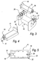
- a device for connecting and insulating a thermal protector and/or a fuse for electrical winding of motors having the structure according to the invention is generally designated by the reference numeral 10.
- the device 10 comprises a rigid tray-like shell 11 made of plastics, which substantially has a rectangular shape, for example for a thermal protector 12 (a component that is sensitive to temperature variations), which in this case has two terminals 17, described in greater detail hereinafter, for electrical contact with the power supply of an electric motor, not shown, as specified more clearly hereinafter, which protrude from the shell 11.
- a thermal protector 12 a component that is sensitive to temperature variations
- two terminals 17, described in greater detail hereinafter for electrical contact with the power supply of an electric motor, not shown, as specified more clearly hereinafter, which protrude from the shell 11.
- the shell 11 is complementarily to a spool 16 of the winding 14 of the motor, whose structure it completes and to which it is coupled before the winding operation.
- the shell 11 has a shape that complements the shape of the spool 16 so that, together, they form a whole structure.
- the shell 11 has two mutually opposite male interlocking components, designated by the reference numerals 18 and 19 respectively, which are complementary to corresponding female interlocking components, designated by the reference numerals 20 and 21 respectively, of the spool 16.
- the male components 18 and 19 lie at right angles to the plane of arrangement of the thermal protector 12 and have a dovetail profile that is shaped complementarily to the respective female components 21 and 22.
- An additional tab-shaped element 23 having a quadrangular profile is parallel to the component 18 and laterally adjacent thereto in order to enter a complementarily shaped seat 33 of the spool 16.
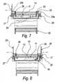
- the male components 18, 19 and the element 23 have respective passages 30, 31 and 32 that can be crossed by electrical terminals, which in the case of Figures 2 and 7 are constituted by the terminals 17 that pass through the component 18 and through the element 23.
- the shell 11 is conveniently arranged adjacent to the position of the windings 14, so that the thermal protector 12 is adjacent thereto and can sense the temperature.
- the electrical contact terminals 17 are constituted by a corresponding number of metallic laminas obtained by blanking and shaping, which protrude from the shell 11 and are partially accommodated in, and rested on, the passages 30, 31 and 32 of the components 18 and 19 and of the element 23.
- Each lamina 17 for the protector 12 has a first portion 17a that is parallel to the protector 12, a second portion 17b that is perpendicular but lies on the same plane, a third portion 17c that is perpendicular to the preceding one (to be inserted in the corresponding passage 30 or 31), and a fourth portion 17d that is parallel to the first one.
- the spool 16 also made of plastics, is conveniently provided with mutually opposite connectors 26 and 27, which accommodate winding connection electrical terminals 28 and 29 for connection to the winding 14 and to the protector 12 and/or to the fuse 24.
- the assembly of the protector and/or of the fuse is substantially guided and practically free from possibilities of assembly errors.
- the particular structure of the protector allows to place it in an optimum situation in order to detect effectively the temperature changes of the winding.
- the structure of the shell of the thermal protector allows to eliminate welded connections.
- the materials and the dimensions may be any according to requirements.
Landscapes
- Engineering & Computer Science (AREA)
- Microelectronics & Electronic Packaging (AREA)
- Power Engineering (AREA)
Claims (10)
- Spulenkörper (16) einer Wicklung (14) eines Motors umfassend eine Wicklung (14) und eine Vorrichtung (10) zum Anschluss und zur Isolierung eines Überhitzungsschutzes (12) und/oder einer Sicherung (24) für elektrische Wicklungen (14) von Motoren, wobei die Vorrichtung (10) umfasst:eine wannenförmige Schale (11), die den Überhitzungsschutz (12) und/oder die Sicherung (24) enthält, wobei der Überhitzungsschutz (12) und/oder die Sicherung (24) eine oder mehrere elektrische Kontaktstellen (17) aufweisen, die von der Schale (11) abstehen, wobei die Schale (11) in Bezug auf den Spulenkörper (16) der Motorwicklung (14) komplementär ist und dessen Struktur vervollständigt, und die Schale (11) eine oder mehrere männliche/weibliche Verriegelungskomponenten (18, 19) aufweist, die zu entsprechenden männlichen/weiblichen Verriegelungskomponenten (20, 21) des Spulenkörpers (16) komplementär sind, wobei die Vorrichtung (10) dadurch gekennzeichnet ist, dass die wannenförmige Schale (11) aus Kunststoff gebildet ist und die Wicklung (14) den Spulenkörper (16) abdeckt, wobei der Spulenkörper (16) komplementär mit der Schale (11) verbunden ist.
- Vorrichtung (10) nach Anspruch 1, dadurch gekennzeichnet, dass die Schale (11) zwei einander gegenüberliegende männliche Verriegelungskomponenten (18, 19) aufweist, die zu entsprechenden weiblichen Verriegelungskomponenten (20, 21) des Spulenkörpers (16) komplementär sind.
- Vorrichtung (10) nach einem oder mehreren der vorhergehenden Ansprüche, dadurch gekennzeichnet, dass die männlichen Verriegelungskomponenten (18, 19) im rechten Winkel zur Ebene der Anordnung des Überhitzungsschutzes (12) und/oder der Sicherung (24) liegen.
- Vorrichtung (10) nach einem oder mehreren der vorhergehenden Ansprüche, dadurch gekennzeichnet, dass die männlichen Verriegelungskomponenten (18, 19) ein Schwalbenschwanzprofil aufweisen, das komplementär zur den jeweiligen weiblichen Komponenten (21, 22) geformt ist.
- Vorrichtung (10) nach einem oder mehreren der vorhergehenden Ansprüche, dadurch gekennzeichnet, dass ein weiteres scheibenförmiges Element (23) mit einem rechtwinkligen Profil parallel und seitlich benachbart zu einer der männlichen Komponenten (18, 19) angeordnet ist, so dass es in einen komplementär geformten Sitz (33) des Spulenkörpers (16) eingreift.
- Vorrichtung (10) nach Anspruch 5, dadurch gekennzeichnet, dass die männlichen Komponenten (18, 19) und das Element (23) mit entsprechenden Durchgängen (30, 31, 32) versehen sind und mit den elektrischen Anschlüssen (17) gekreuzt werden können.
- Vorrichtung (10) nach den Ansprüchen 1 und 6, dadurch gekennzeichnet, dass die elektrischen Anschlüsse (17) durch Metallstreifen gebildet sind, die durch Stanzen und Formen erhalten sind.
- Vorrichtung (10) nach Anspruch 6, dadurch gekennzeichnet, dass jeder der Anschlüsse (17) für den Überhitzungsschutz (12) ein Streifen ist, der mit einem ersten Teil (17a) versehen ist, der zum Überhitzungsschutz (12) parallel ist, einem zweiten Teil (17b) versehen ist, der zum Überhitzungsschutz (12) senkrecht ist, aber in der selben Ebene liegt, einem dritten Teil (17c) versehen ist, der zum vorhergehenden senkrecht ist, so dass er in den entsprechenden Durchgang (30, 31) eingesetzt werden kann, und einem vierten Teil (17d) versehen ist, der zum ersten Teil (17a) parallel ist.
- Vorrichtung (10) nach den Ansprüchen 7 oder 8, dadurch gekennzeichnet, dass die Metallstreifen von der Schale (11) abstehen und teilweise in den Durchgängen (30, 31, 32) der männlichen Komponenten (18, 19) und dem Element (23) angeordnet sind und daran anliegen.
- Vorrichtung (10) nach einem oder mehreren der vorhergehenden Ansprüche, dadurch gekennzeichnet, dass der Spulenkörper (16) mit einander gegenüberliegenden Verbindungselementen (26, 27) versehen ist, die elektrische Anschlüsse (28, 29) zur Verbindung mit der Wicklung (14) und dem Überhitzungsschutz (12) und/oder der Sicherung (24) aufnehmen.
Applications Claiming Priority (2)
| Application Number | Priority Date | Filing Date | Title |
|---|---|---|---|
| ITPD20020094 | 2002-04-15 | ||
| IT2002PD000094A ITPD20020094A1 (it) | 2002-04-15 | 2002-04-15 | Dispositivo per la connessione e l'isolamento di un protettore termico e/o di un fusibile per avvolgimenti elettrici di motori. |
Publications (2)
| Publication Number | Publication Date |
|---|---|
| EP1355406A1 EP1355406A1 (de) | 2003-10-22 |
| EP1355406B1 true EP1355406B1 (de) | 2007-05-16 |
Family
ID=28460729
Family Applications (1)
| Application Number | Title | Priority Date | Filing Date |
|---|---|---|---|
| EP03004987A Expired - Lifetime EP1355406B1 (de) | 2002-04-15 | 2003-03-11 | Vorrichtung zum Anschluss und zur Isolierung eines Überhitzungsschutzes und/oder einer Sicherung für die elektrischen Wicklungen eines Motors |
Country Status (6)
| Country | Link |
|---|---|
| US (1) | US7046495B2 (de) |
| EP (1) | EP1355406B1 (de) |
| AT (1) | ATE362671T1 (de) |
| DE (1) | DE60313823T2 (de) |
| ES (1) | ES2284998T3 (de) |
| IT (1) | ITPD20020094A1 (de) |
Cited By (1)
| Publication number | Priority date | Publication date | Assignee | Title |
|---|---|---|---|---|
| EP2124320A2 (de) | 2008-05-20 | 2009-11-25 | MIELE & CIE. KG | Elektromotor mit Sensor und/oder Thermoschutzschalter |
Families Citing this family (10)
| Publication number | Priority date | Publication date | Assignee | Title |
|---|---|---|---|---|
| ITPD20060361A1 (it) * | 2006-10-03 | 2008-04-04 | Inarca Spa | Gruppo di connessione di una scheda elettronica di controllo agli avvolgimenti statorici di un motore elettrico per tende a rullo o similari |
| JP5693138B2 (ja) * | 2010-10-19 | 2015-04-01 | 三菱重工業株式会社 | 密閉型電動圧縮機 |
| KR101495023B1 (ko) | 2011-01-21 | 2015-02-24 | 브로제 파르초이크타일레 게엠베하 운트 코. 카게, 뷔르츠부르크 | 특히 모터 차량 부품의 제어 전자기기를 위한 보호 장치 |
| DE202011001820U1 (de) * | 2011-01-21 | 2012-04-27 | Brose Fahrzeugteile GmbH & Co. Kommanditgesellschaft, Würzburg | Schutzvorrichtung für die Steuerelektronik einer Kraftfahrzeugkomponente |
| JP6259715B2 (ja) * | 2014-05-30 | 2018-01-10 | Kyb株式会社 | 回転電機 |
| CN108309131A (zh) * | 2018-04-14 | 2018-07-24 | 江阴市志翔电子科技有限公司 | 智能坐便器温控器 |
| US12057754B2 (en) * | 2019-09-30 | 2024-08-06 | Jiangsu Leili Motor Co., Ltd. | Motor with flame-resistant terminal connecting device and lead portion |
| JP7728142B2 (ja) * | 2021-10-18 | 2025-08-22 | 株式会社マキタ | 電動作業機 |
| DE102021133376A1 (de) | 2021-12-15 | 2023-06-15 | Hanning Elektro-Werke Gmbh & Co. Kg | Thermoschalter-Anschlussanordnung und Herstellverfahren hierfür |
| DE102022116095A1 (de) * | 2022-06-28 | 2023-12-28 | Sysko AG Systeme & Komponenten | Treiberspulenvorrichtung |
Family Cites Families (5)
| Publication number | Priority date | Publication date | Assignee | Title |
|---|---|---|---|---|
| US4132913A (en) * | 1976-11-22 | 1979-01-02 | Gould Inc. | Field-coil bobbin with built-in-one-shot thermal protector |
| JPH0779536B2 (ja) * | 1987-10-30 | 1995-08-23 | 三菱電機株式会社 | 電動機 |
| DE8914335U1 (de) * | 1989-12-06 | 1990-02-08 | Licentia Patent-Verwaltungs-Gmbh, 6000 Frankfurt | Aufnahmegehäuse für einen Thermoschutzschalter |
| DE19852929C1 (de) * | 1998-11-17 | 2000-03-30 | Hanning Elektro Werke | Thermoschalter-Anordnung für elektromagnetische Spulen |
| IT1315706B1 (it) * | 2000-06-05 | 2003-03-18 | Inarca Spa | Rocchetto perfezionato per avvolgimenti elettrici di motori |
-
2002
- 2002-04-15 IT IT2002PD000094A patent/ITPD20020094A1/it unknown
-
2003
- 2003-03-11 EP EP03004987A patent/EP1355406B1/de not_active Expired - Lifetime
- 2003-03-11 DE DE60313823T patent/DE60313823T2/de not_active Expired - Lifetime
- 2003-03-11 AT AT03004987T patent/ATE362671T1/de not_active IP Right Cessation
- 2003-03-11 ES ES03004987T patent/ES2284998T3/es not_active Expired - Lifetime
- 2003-03-14 US US10/387,449 patent/US7046495B2/en not_active Expired - Fee Related
Cited By (2)
| Publication number | Priority date | Publication date | Assignee | Title |
|---|---|---|---|---|
| EP2124320A2 (de) | 2008-05-20 | 2009-11-25 | MIELE & CIE. KG | Elektromotor mit Sensor und/oder Thermoschutzschalter |
| DE102008024378A1 (de) * | 2008-05-20 | 2009-12-03 | Miele & Cie. Kg | Elektromotor mit Sensor und/oder Thermoschutzschalter |
Also Published As
| Publication number | Publication date |
|---|---|
| ITPD20020094A1 (it) | 2003-10-15 |
| DE60313823D1 (de) | 2007-06-28 |
| ATE362671T1 (de) | 2007-06-15 |
| DE60313823T2 (de) | 2008-01-24 |
| ES2284998T3 (es) | 2007-11-16 |
| EP1355406A1 (de) | 2003-10-22 |
| US20030193768A1 (en) | 2003-10-16 |
| US7046495B2 (en) | 2006-05-16 |
Similar Documents
| Publication | Publication Date | Title |
|---|---|---|
| US7579732B2 (en) | Insulating motor housing | |
| JP4295319B2 (ja) | 回路支持体を有する回転電機 | |
| EP1909362B1 (de) | Anordnung für den Anschluss einer elektronischen Schalttafel an die Statorwicklungen eines Elektromotors für Rollladen o.Ä. | |
| US10756592B2 (en) | Contacting arrangement between a stator and a circuit board | |
| US10044239B2 (en) | Stator of electric motor, electric motor, air conditioner, and method of manufacturing stator of electric motor | |
| US11843296B2 (en) | Motor and air conditioner | |
| US7046495B2 (en) | Device for connecting and insulating a thermal protector and/or a fuse for electrical windings of motors | |
| US9954412B2 (en) | Electric motor, air conditioner, and electric apparatus | |
| EP2798725B1 (de) | Elektromotor mit einem thermoschalter | |
| US6326879B1 (en) | Thermal switch arrangement for electromagnetic coils | |
| WO2014080675A1 (ja) | 電動機、空気調和機、および電動機の製造方法 | |
| US6744160B2 (en) | Device for connecting and insulating a thermal protector for electrical windings of motors | |
| EP3062423B1 (de) | Elektromotor, klimaanlage und elektrisches gerät | |
| WO2011056392A1 (en) | Motor assembly with switch module | |
| US20090009014A1 (en) | Stator end disk for a commutator motor and corresponding commutator motor | |
| JPH087741A (ja) | 電気機器の端子カバー | |
| SI9400264A (en) | Electromotor with sheet metal holder | |
| JP5132425B2 (ja) | 電気的接続部品の加工方法 | |
| JPH0793096B2 (ja) | 漏電遮断器 | |
| EP1441433B1 (de) | Verbindungsanordnung, insbesondere für die Statorwicklungen eines Elektromotor | |
| KR102608044B1 (ko) | 고정자 조립체를 제조하기 위한 방법, 및 고정자 조립체 | |
| JP2022080937A (ja) | 端子部絶縁構造および電気接続箱 | |
| JPH06245425A (ja) | 回転電機の固定子 | |
| JPH05332469A (ja) | 電磁弁の製造方法 | |
| HK1018923B (en) | Terminal pin structure of resolver |
Legal Events
| Date | Code | Title | Description |
|---|---|---|---|
| PUAI | Public reference made under article 153(3) epc to a published international application that has entered the european phase |
Free format text: ORIGINAL CODE: 0009012 |
|
| AK | Designated contracting states |
Kind code of ref document: A1 Designated state(s): AT BE BG CH CY CZ DE DK EE ES FI FR GB GR HU IE IT LI LU MC NL PT RO SE SI SK TR |
|
| AX | Request for extension of the european patent |
Extension state: AL LT LV MK |
|
| 17P | Request for examination filed |
Effective date: 20040301 |
|
| 17Q | First examination report despatched |
Effective date: 20040407 |
|
| AKX | Designation fees paid |
Designated state(s): AT BE BG CH CY CZ DE DK EE ES FI FR GB GR HU IE IT LI LU MC NL PT RO SE SI SK TR |
|
| GRAP | Despatch of communication of intention to grant a patent |
Free format text: ORIGINAL CODE: EPIDOSNIGR1 |
|
| GRAS | Grant fee paid |
Free format text: ORIGINAL CODE: EPIDOSNIGR3 |
|
| GRAA | (expected) grant |
Free format text: ORIGINAL CODE: 0009210 |
|
| AK | Designated contracting states |
Kind code of ref document: B1 Designated state(s): AT BE BG CH CY CZ DE DK EE ES FI FR GB GR HU IE IT LI LU MC NL PT RO SE SI SK TR |
|
| PG25 | Lapsed in a contracting state [announced via postgrant information from national office to epo] |
Ref country code: FI Free format text: LAPSE BECAUSE OF FAILURE TO SUBMIT A TRANSLATION OF THE DESCRIPTION OR TO PAY THE FEE WITHIN THE PRESCRIBED TIME-LIMIT Effective date: 20070516 |
|
| REG | Reference to a national code |
Ref country code: GB Ref legal event code: FG4D |
|
| REG | Reference to a national code |
Ref country code: CH Ref legal event code: EP |
|
| REG | Reference to a national code |
Ref country code: IE Ref legal event code: FG4D |
|
| REF | Corresponds to: |
Ref document number: 60313823 Country of ref document: DE Date of ref document: 20070628 Kind code of ref document: P |
|
| REG | Reference to a national code |
Ref country code: SE Ref legal event code: TRGR |
|
| REG | Reference to a national code |
Ref country code: CH Ref legal event code: NV Representative=s name: ROTTMANN, ZIMMERMANN + PARTNER AG |
|
| REG | Reference to a national code |
Ref country code: HU Ref legal event code: AG4A Ref document number: E001660 Country of ref document: HU |
|
| REG | Reference to a national code |
Ref country code: RO Ref legal event code: EPE |
|
| NLV1 | Nl: lapsed or annulled due to failure to fulfill the requirements of art. 29p and 29m of the patents act | ||
| ET | Fr: translation filed | ||
| REG | Reference to a national code |
Ref country code: ES Ref legal event code: FG2A Ref document number: 2284998 Country of ref document: ES Kind code of ref document: T3 |
|
| PG25 | Lapsed in a contracting state [announced via postgrant information from national office to epo] |
Ref country code: BE Free format text: LAPSE BECAUSE OF FAILURE TO SUBMIT A TRANSLATION OF THE DESCRIPTION OR TO PAY THE FEE WITHIN THE PRESCRIBED TIME-LIMIT Effective date: 20070516 |
|
| PG25 | Lapsed in a contracting state [announced via postgrant information from national office to epo] |
Ref country code: SI Free format text: LAPSE BECAUSE OF FAILURE TO SUBMIT A TRANSLATION OF THE DESCRIPTION OR TO PAY THE FEE WITHIN THE PRESCRIBED TIME-LIMIT Effective date: 20070516 Ref country code: PT Free format text: LAPSE BECAUSE OF FAILURE TO SUBMIT A TRANSLATION OF THE DESCRIPTION OR TO PAY THE FEE WITHIN THE PRESCRIBED TIME-LIMIT Effective date: 20071016 Ref country code: NL Free format text: LAPSE BECAUSE OF FAILURE TO SUBMIT A TRANSLATION OF THE DESCRIPTION OR TO PAY THE FEE WITHIN THE PRESCRIBED TIME-LIMIT Effective date: 20070516 Ref country code: DK Free format text: LAPSE BECAUSE OF FAILURE TO SUBMIT A TRANSLATION OF THE DESCRIPTION OR TO PAY THE FEE WITHIN THE PRESCRIBED TIME-LIMIT Effective date: 20070516 |
|
| PLBE | No opposition filed within time limit |
Free format text: ORIGINAL CODE: 0009261 |
|
| STAA | Information on the status of an ep patent application or granted ep patent |
Free format text: STATUS: NO OPPOSITION FILED WITHIN TIME LIMIT |
|
| 26N | No opposition filed |
Effective date: 20080219 |
|
| PG25 | Lapsed in a contracting state [announced via postgrant information from national office to epo] |
Ref country code: GR Free format text: LAPSE BECAUSE OF FAILURE TO SUBMIT A TRANSLATION OF THE DESCRIPTION OR TO PAY THE FEE WITHIN THE PRESCRIBED TIME-LIMIT Effective date: 20070817 |
|
| PG25 | Lapsed in a contracting state [announced via postgrant information from national office to epo] |
Ref country code: MC Free format text: LAPSE BECAUSE OF NON-PAYMENT OF DUE FEES Effective date: 20080331 |
|
| PG25 | Lapsed in a contracting state [announced via postgrant information from national office to epo] |
Ref country code: EE Free format text: LAPSE BECAUSE OF FAILURE TO SUBMIT A TRANSLATION OF THE DESCRIPTION OR TO PAY THE FEE WITHIN THE PRESCRIBED TIME-LIMIT Effective date: 20070516 Ref country code: IE Free format text: LAPSE BECAUSE OF NON-PAYMENT OF DUE FEES Effective date: 20080311 |
|
| PGFP | Annual fee paid to national office [announced via postgrant information from national office to epo] |
Ref country code: AT Payment date: 20090325 Year of fee payment: 7 Ref country code: HU Payment date: 20090311 Year of fee payment: 7 |
|
| PGFP | Annual fee paid to national office [announced via postgrant information from national office to epo] |
Ref country code: BG Payment date: 20090310 Year of fee payment: 7 Ref country code: CZ Payment date: 20090309 Year of fee payment: 7 Ref country code: RO Payment date: 20090119 Year of fee payment: 7 Ref country code: SK Payment date: 20090227 Year of fee payment: 7 |
|
| PGFP | Annual fee paid to national office [announced via postgrant information from national office to epo] |
Ref country code: CH Payment date: 20090226 Year of fee payment: 7 Ref country code: GB Payment date: 20090330 Year of fee payment: 7 |
|
| PG25 | Lapsed in a contracting state [announced via postgrant information from national office to epo] |
Ref country code: CY Free format text: LAPSE BECAUSE OF FAILURE TO SUBMIT A TRANSLATION OF THE DESCRIPTION OR TO PAY THE FEE WITHIN THE PRESCRIBED TIME-LIMIT Effective date: 20070516 |
|
| PGFP | Annual fee paid to national office [announced via postgrant information from national office to epo] |
Ref country code: SE Payment date: 20090318 Year of fee payment: 7 Ref country code: TR Payment date: 20090303 Year of fee payment: 7 |
|
| PG25 | Lapsed in a contracting state [announced via postgrant information from national office to epo] |
Ref country code: LU Free format text: LAPSE BECAUSE OF NON-PAYMENT OF DUE FEES Effective date: 20080311 |
|
| REG | Reference to a national code |
Ref country code: CH Ref legal event code: PL |
|
| EUG | Se: european patent has lapsed | ||
| GBPC | Gb: european patent ceased through non-payment of renewal fee |
Effective date: 20100311 |
|
| PG25 | Lapsed in a contracting state [announced via postgrant information from national office to epo] |
Ref country code: CZ Free format text: LAPSE BECAUSE OF NON-PAYMENT OF DUE FEES Effective date: 20100311 Ref country code: AT Free format text: LAPSE BECAUSE OF NON-PAYMENT OF DUE FEES Effective date: 20100311 |
|
| REG | Reference to a national code |
Ref country code: SK Ref legal event code: MM4A Ref document number: E 1913 Country of ref document: SK Effective date: 20100311 |
|
| PG25 | Lapsed in a contracting state [announced via postgrant information from national office to epo] |
Ref country code: BG Free format text: LAPSE BECAUSE OF NON-PAYMENT OF DUE FEES Effective date: 20101031 Ref country code: HU Free format text: LAPSE BECAUSE OF NON-PAYMENT OF DUE FEES Effective date: 20100312 Ref country code: LI Free format text: LAPSE BECAUSE OF NON-PAYMENT OF DUE FEES Effective date: 20100331 Ref country code: SK Free format text: LAPSE BECAUSE OF NON-PAYMENT OF DUE FEES Effective date: 20100311 Ref country code: CH Free format text: LAPSE BECAUSE OF NON-PAYMENT OF DUE FEES Effective date: 20100331 |
|
| PG25 | Lapsed in a contracting state [announced via postgrant information from national office to epo] |
Ref country code: GB Free format text: LAPSE BECAUSE OF NON-PAYMENT OF DUE FEES Effective date: 20100311 |
|
| PG25 | Lapsed in a contracting state [announced via postgrant information from national office to epo] |
Ref country code: RO Free format text: LAPSE BECAUSE OF NON-PAYMENT OF DUE FEES Effective date: 20100311 |
|
| PG25 | Lapsed in a contracting state [announced via postgrant information from national office to epo] |
Ref country code: SE Free format text: LAPSE BECAUSE OF NON-PAYMENT OF DUE FEES Effective date: 20100312 |
|
| PG25 | Lapsed in a contracting state [announced via postgrant information from national office to epo] |
Ref country code: TR Free format text: LAPSE BECAUSE OF NON-PAYMENT OF DUE FEES Effective date: 20100311 |
|
| PGFP | Annual fee paid to national office [announced via postgrant information from national office to epo] |
Ref country code: FR Payment date: 20130327 Year of fee payment: 11 Ref country code: DE Payment date: 20130326 Year of fee payment: 11 Ref country code: ES Payment date: 20130228 Year of fee payment: 11 |
|
| REG | Reference to a national code |
Ref country code: DE Ref legal event code: R119 Ref document number: 60313823 Country of ref document: DE |
|
| REG | Reference to a national code |
Ref country code: FR Ref legal event code: ST Effective date: 20141128 |
|
| REG | Reference to a national code |
Ref country code: DE Ref legal event code: R119 Ref document number: 60313823 Country of ref document: DE Effective date: 20141001 |
|
| PG25 | Lapsed in a contracting state [announced via postgrant information from national office to epo] |
Ref country code: DE Free format text: LAPSE BECAUSE OF NON-PAYMENT OF DUE FEES Effective date: 20141001 Ref country code: FR Free format text: LAPSE BECAUSE OF NON-PAYMENT OF DUE FEES Effective date: 20140331 |
|
| REG | Reference to a national code |
Ref country code: ES Ref legal event code: FD2A Effective date: 20150424 |
|
| PG25 | Lapsed in a contracting state [announced via postgrant information from national office to epo] |
Ref country code: ES Free format text: LAPSE BECAUSE OF NON-PAYMENT OF DUE FEES Effective date: 20140312 |
|
| PGFP | Annual fee paid to national office [announced via postgrant information from national office to epo] |
Ref country code: IT Payment date: 20181221 Year of fee payment: 17 |
|
| PG25 | Lapsed in a contracting state [announced via postgrant information from national office to epo] |
Ref country code: IT Free format text: LAPSE BECAUSE OF NON-PAYMENT OF DUE FEES Effective date: 20200311 |