EP1355497A2 - Appareil de codage et décodage de séquences vidéo - Google Patents
Appareil de codage et décodage de séquences vidéo Download PDFInfo
- Publication number
- EP1355497A2 EP1355497A2 EP20030011993 EP03011993A EP1355497A2 EP 1355497 A2 EP1355497 A2 EP 1355497A2 EP 20030011993 EP20030011993 EP 20030011993 EP 03011993 A EP03011993 A EP 03011993A EP 1355497 A2 EP1355497 A2 EP 1355497A2
- Authority
- EP
- European Patent Office
- Prior art keywords
- data
- subbands
- coefficient
- decoding
- components
- Prior art date
- Legal status (The legal status is an assumption and is not a legal conclusion. Google has not performed a legal analysis and makes no representation as to the accuracy of the status listed.)
- Withdrawn
Links
Images


Classifications
-
- H—ELECTRICITY
- H04—ELECTRIC COMMUNICATION TECHNIQUE
- H04N—PICTORIAL COMMUNICATION, e.g. TELEVISION
- H04N11/00—Colour television systems
- H04N11/04—Colour television systems using pulse code modulation
- H04N11/042—Codec means
-
- H—ELECTRICITY
- H04—ELECTRIC COMMUNICATION TECHNIQUE
- H04N—PICTORIAL COMMUNICATION, e.g. TELEVISION
- H04N19/00—Methods or arrangements for coding, decoding, compressing or decompressing digital video signals
- H04N19/10—Methods or arrangements for coding, decoding, compressing or decompressing digital video signals using adaptive coding
- H04N19/102—Methods or arrangements for coding, decoding, compressing or decompressing digital video signals using adaptive coding characterised by the element, parameter or selection affected or controlled by the adaptive coding
- H04N19/129—Scanning of coding units, e.g. zig-zag scan of transform coefficients or flexible macroblock ordering [FMO]
-
- H—ELECTRICITY
- H04—ELECTRIC COMMUNICATION TECHNIQUE
- H04N—PICTORIAL COMMUNICATION, e.g. TELEVISION
- H04N19/00—Methods or arrangements for coding, decoding, compressing or decompressing digital video signals
- H04N19/10—Methods or arrangements for coding, decoding, compressing or decompressing digital video signals using adaptive coding
- H04N19/169—Methods or arrangements for coding, decoding, compressing or decompressing digital video signals using adaptive coding characterised by the coding unit, i.e. the structural portion or semantic portion of the video signal being the object or the subject of the adaptive coding
- H04N19/186—Methods or arrangements for coding, decoding, compressing or decompressing digital video signals using adaptive coding characterised by the coding unit, i.e. the structural portion or semantic portion of the video signal being the object or the subject of the adaptive coding the unit being a colour or a chrominance component
-
- H—ELECTRICITY
- H04—ELECTRIC COMMUNICATION TECHNIQUE
- H04N—PICTORIAL COMMUNICATION, e.g. TELEVISION
- H04N19/00—Methods or arrangements for coding, decoding, compressing or decompressing digital video signals
- H04N19/30—Methods or arrangements for coding, decoding, compressing or decompressing digital video signals using hierarchical techniques, e.g. scalability
- H04N19/36—Scalability techniques involving formatting the layers as a function of picture distortion after decoding, e.g. signal-to-noise [SNR] scalability
-
- H—ELECTRICITY
- H04—ELECTRIC COMMUNICATION TECHNIQUE
- H04N—PICTORIAL COMMUNICATION, e.g. TELEVISION
- H04N19/00—Methods or arrangements for coding, decoding, compressing or decompressing digital video signals
- H04N19/60—Methods or arrangements for coding, decoding, compressing or decompressing digital video signals using transform coding
- H04N19/61—Methods or arrangements for coding, decoding, compressing or decompressing digital video signals using transform coding in combination with predictive coding
-
- H—ELECTRICITY
- H04—ELECTRIC COMMUNICATION TECHNIQUE
- H04N—PICTORIAL COMMUNICATION, e.g. TELEVISION
- H04N19/00—Methods or arrangements for coding, decoding, compressing or decompressing digital video signals
- H04N19/60—Methods or arrangements for coding, decoding, compressing or decompressing digital video signals using transform coding
- H04N19/63—Methods or arrangements for coding, decoding, compressing or decompressing digital video signals using transform coding using sub-band based transform, e.g. wavelets
- H04N19/64—Methods or arrangements for coding, decoding, compressing or decompressing digital video signals using transform coding using sub-band based transform, e.g. wavelets characterised by ordering of coefficients or of bits for transmission
-
- H—ELECTRICITY
- H04—ELECTRIC COMMUNICATION TECHNIQUE
- H04N—PICTORIAL COMMUNICATION, e.g. TELEVISION
- H04N19/00—Methods or arrangements for coding, decoding, compressing or decompressing digital video signals
- H04N19/10—Methods or arrangements for coding, decoding, compressing or decompressing digital video signals using adaptive coding
- H04N19/102—Methods or arrangements for coding, decoding, compressing or decompressing digital video signals using adaptive coding characterised by the element, parameter or selection affected or controlled by the adaptive coding
- H04N19/13—Adaptive entropy coding, e.g. adaptive variable length coding [AVLC] or context adaptive binary arithmetic coding [CABAC]
Definitions
- the present invention pertains to the field of digital video processing and relates to a video coding device for efficiently encoding video data and a video decoding device for decoding video data coded by the video coding device.
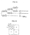
- the well-known high-efficient subband encoding method is used to decompose an input image into frequency bands by a bank of band-decomposing filters.
- the band-decomposing filter-bank is a one-dimensional filter-bank that can serve as a two-dimensional band-decomposing filter-bank by repeating processing of the input image in horizontal and vertical directions. This method was reported by Fujii, Noumura. "Topics on Wavelet Transform" in a Report of "TECHNICAL REPORT of IEICE, IE92-11, 1992".
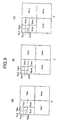
- a subband image as shown in Fig. 1B obtained by conducting two-dimensional subband decomposition three times.
- the first two-dimensional subband decomposition obtains a horizontal high-pass and a vertical low-pass band, a horizontal low-pass and vertical high-pass band and a horizontal and vertical high-pass band, which are designated by HL1, LH1 and HH1 respectively.
- a horizontal and vertical low-pass band obtained by the first decomposition is further subjected to two-dimensional band-decomposition by which three subbands HL2, LH2 and HH2 are obtained.
- a horizontal and vertical low-pass subband obtained by the second decomposition is further subjected to third two-dimensional subband decomposition by which three subbands HL3, LH3 and HH3 and a horizontal and vertical low-pass subband LL3 are obtained.
- a Wavelet-converting filter-bank or a band-decomposing and synthesizing filter-bank may be used as the band-decomposing filter-bank.
- the decomposed subband-images are of a hierarchical (layer) structure from low-frequency band to high-frequency band.
- the progressive image transmitting method enables a video decoding device to reproduce a low-resolution image by using only a part of coded data. The more coded data is reproduced, the higher resolution the decoded image has.
- Japanese Laid-Open Patent Publication (TOKKAI HEI) No. 8-242379 describes a system (referred hereinafter to as a prior art system) to realize the progressive image transmitting.
- a video coding device using in the prior art system comprises a subband decomposing portion for decomposing an input image into subband images by using two-dimensional decomposing filters, a coefficient coding portion for encoding coefficients of the decomposed subband images, a variable-length coding portion for performing variable-length coding of the coded coefficient data from the coefficient coding portion and a line-transmitting portion for transmitting a plurality of components composing the image per line at a time.
- the coefficient coding portion performs encoding the coefficients by using any one of various kinds of coding methods (e.g., DPCM coding, zero-tree coding, and scalar-quantizing coding). This process includes a quantizing step.
- the line-transmitting portion transmits the components Y, U and V sequentially line by line in the order from the first line of the subband LL3. Having transferred all lines of the subband LL3, the portion transfers the components Y, U and V in the subbands LH3, HL3 and HH3 respectively in the order: the component Y on the first lines of the subbands LH3, HL3 and HH3; the component U on the first lines of the subbands LH3, HL3 and HH3; the component V on the first lines of the subbands LH3, HL3 and HH3; the component Y on the second lines of the subbands LH3, HL3 and HH3; U on the second lines of LH3, HL3 and HH3; V on the second lines of the subbands LH3, HL3 and HH3 and so on.
- the line transmitting portion transfers, in similar way, lines of LH2, HL2, HH2 and, then, lines of LH1, HL1, HH1.
- the above-mentioned procedure of the line-transmitting portion is executed according to a programed flow.
- the prior art video decoding device comprises a line receiving portion for receiving the coded data from the line-transmitting portion of the video-coding device above-mentioned and rearranging the data to respective component groups, a variable-length decoding portion for decoding the rearranged variable-length-coded data, a decoded data counting portion for counting bits of data decoded by the variable-length decoding portion, a decoding truncating portion for comparing the number of the bits counted by the decoded-data counting portion with a preset threshold or an externally-given threshold to give a command for stopping the decoding operation of the variable-length decoding portion when the number of decoded bits exceeds the threshold, a data completing portion for compensating for lack of truncated data by adding zero when having truncated the decoding the coded data at the specified number of bits, a coefficient decoding portion for decoding coded coefficient data by reversing the same processing procedure of the coefficient coding portion and a subband synthesizing portion
- the video decoding device can thus reproduce an entire image from coded data having a hierarchical structure or a part thereof.
- the conventional video-coding and video-decoding system can realize progressive image transmitting by transmitting image components per line in an ascending order starting from the lowest-resolution band-image.
- the prior art system encounters several inconvenient problems resulting from the fixed transfer-unit of a line. For example, an image composed of luminance component Y and chrominance components U and V may be easier recognized by transmitting only the component Y before the components U and V rather than transmitting all components as a unit.
- the prior art system presumes that components of an image have the same size. Therefore, it cannot be adaptable to an input image composed of different sizes of components in format of, e.g., 4:2:2 or 4:2:0.
- the present invention is directed to a system for effective progressive image transmitting by solving the foregoing problems involved in the prior arts.
- the devices can first separate and transmit lowest-resolution subbands of respective components A n to first give a summary content of an image, making it possible to improve subjective quality of the reproduced image.
- the well-known high-efficient subband encoding method is used to decompose an input image into such frequency bands as shown in Fig. 1B by a bank of band-decomposing filters as shown in Fig. 1A.
- the band-decomposing filter-bank shown in Fig. 1A is a one-dimensional filter-bank that can serve as a two-dimensional band-decomposing filter-bank by repeating processing the input image in horizontal and vertical directions. This method was reported by Fujii, Noumura. "Topics on Wavelet Transform" in a Report of "TECHNICAL REPORT of IEICE, IE92-11, 1992".
- Fig. 1B there is shown a subband image obtained by conducting two-dimensional subband decomposition three times.
- the first two-dimensional subband decomposition obtains a horizontal high-pass and a vertical low-pass band, a horizontal low-pass and vertical high-pass band and a horizontal and vertical high-pass band, which are designated by HL1, LH1 and HH1 respectively.
- a horizontal and vertical low-pass band obtained by the first decomposition is further subjected to two-dimensional band-decomposition by which three subbands HL2, LH2 and HH2 are obtained.
- a horizontal and vertical low-pass subband obtained by the second decomposition is further subjected to third two-dimensional subband decomposition by which three subbands HL3, LH3 and HH3 and a horizontal and vertical low-pass subband LL3 are obtained.
- a Wavelet-converting filter-bank or a band-decomposing and synthesizing filter-bank may be used as the band-decomposing filter-bank.
- the decomposed subband-images are of a hierarchical (layer) structure from low-frequency band to high-frequency band.
- the progressive image transmitting method enables a video decoding device to reproduce a low-resolution image by using only a part of coded data. The more coded data is reproduced, the higher resolution the decoded image has.
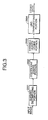
- Japanese Laid-Open Patent Publication (TOKKAI HEI) No. 8-242379 describes a system (referred hereinafter to as a prior art system) to realize the progressive image transmitting, which structure is shown in Figs. 3 and 4.
- Fig. 3 shows a video coding device using in the prior art system
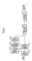
- Fig. 4 shows a video decoding device using the system.
- the video coding device as shown in Fig. 3 comprises a subband decomposing portion 2001 for decomposing an input image into subband images by using two-dimensional decomposing filters, a coefficient coding portion 2002 for encoding coefficients of the decomposed subband images, a variable-length coding portion 2003 for performing variable-length coding of the coded coefficient data from the coefficient coding portion 2002 and a line-transmitting portion 2004 for transmitting a plurality of components composing the image per line at a time.
- the coefficient coding portion 2002 performs encoding the coefficients by using any one of various kinds of coding methods (e.g., DPCM coding, zero-tree coding, and scalar-quantizing coding). This process includes a quantizing step.
- the line-transmitting portion 2004 transmits the components Y, U and V sequentially line by line in the order from the first line of the subband LL3. Having transferred all lines of the subband LL3, the portion transfers the components Y, U and V in the subbands LH3, HL3 and HH3 respectively in the order: the component Y on the first lines of the subbands LH3, HL3 and HH3; the component U on the first lines of the subbands LH3, HL3 and HH3; the component V on the first lines of the subbands LH3, HL3 and HH3; the component Y on the second lines of the subbands LH3, HL3 and HH3; U on the second lines of LH3, HL3 and HH3; V on the second lines of the subbands LH3, HL3 and HH3 and so on.
- the line transmitting portion transfers, in similar way, lines of LH2, HL2, HH2 and, then, lines of LH1, HL1, HH1.
- the above-mentioned procedure of the line-transmitting portion 2004 is illustrated by a flowchart of Fig. 6.
- the video decoding device comprises a line receiving portion 2104 for receiving the coded data from the line-transmitting portion 2004 of the video-coding device of Fig. 3 and rearranging the data to respective component groups, a variable-length decoding portion 2101 for decoding the rearranged variable-length-coded data, a decoded data counting portion 2102 for counting bits of data decoded by the variable-length decoding portion, a decoding truncating portion 2103 for comparing the number of the bits counted by the decoded-data counting portion with a preset threshold or an externally-given threshold to give a command for stopping the decoding operation of the variable-length decoding portion 2101 when the number of decoded bits exceeds the threshold, a data completing portion 2105 for compensating for lack of truncated data by adding zero when having truncated the decoding of the coded data at the specified number of bits, a coefficient decoding portion 2106 for decoding coded coefficient data by reversing the
- the video decoding device can thus reproduce an entire image from coded data having a hierarchical structure or a part thereof.
- the conventional video-coding and video-decoding system can realize progressive image transmitting by transmitting image components per line in an ascending order starting from the lowest-resolution band-image.
- the prior art system encounters several inconvenient problems resulting from the fixed transfer-unit of a line. For example, an image composed of luminance component Y and chrominance components U and V may be easier recognized by transmitting only the component Y before the components U and V rather than transmitting all components as a unit.
- the prior art system presumes that components of an image have the same size. Therefore, it cannot be adaptable to an input image composed of different sizes of components in format of, e.g., 4:2:2 or 4:2:0.
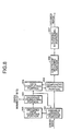
- Fig. 7 is a block diagram showing a video coding device which is a first embodiment of the present invention.
- the first embodiment of the present invention includes a subband decomposing portion (subband decomposing means) 101, a coefficient coding portion (coefficient coding means) 102 and a variable-length coding portion (variable-length coding means) 103, which are similar in construction to portions 2001, 2002 and 2003, respectively, of Fig. 3.
- numeral 104 designates a transfer-order deciding and rearranging portion (rearranging means) that decides an integrated component unit prepared by combining luminance or chrominance elements from coded coefficient data provided from the coefficient coding portion 102 and arranges coded coefficient data of subbands in a transmitting order starting from the coded coefficient data of the lowest-resolution subband.
- the prior art video-coding device rearranges coded coefficient data in the transmitting order after variable-length coding of the data
- the video-coding device according to the present invention rearranges the coded coefficient data in the transmitting order before variable-length coding of the data.
- variable-length coding of the coded coefficient data by, e.g., an arithmetic coding method besides the Huffman coding method.
- the operation of the first embodiment is described below with an input image composed of three components Y (luminance), U (chrominance) and V (chrominance), which is the same as that used in the prior art device. In this embodiment, these components have the same resolution, i.e., the same image sizes.
- An integrated component unit may be prepared from coefficient-coded data by combining elements Y, U and V.
- the following example is an integrated component unit that is prepared of subbands of Y, U and V.
- Fig. 9 shows coefficients of subband images obtained through performing three times of subband-decomposition of respective image components Y, U and V ((a), (b) and (c) part of Fig. 9, respectively).
- the image sizes of the components Y, U and V are equal to each other.
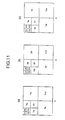
- Figs. 10 and 11 show the order of transmitting the subband image coefficients of Y, U and V ((a), (b) and (c) part of both of Fig.10 and Fig. 11) in Fig. 9, respectively.
- Characters Y, U and V with numeral suffixes in both of Figs. 10, 11 denote the order of transmitting subbands of respective components.
- the transmitting order is as follows: (Y 1 , U 1 , V 1 ), (Y 2 , U 2 , V 2 ), ..., (Y 10 , U 10 , V 10 ).
- a coefficient of high resolution in a horizontal direction is transferred before a coefficient of high resolution in vertical direction
- a coefficient of high resolution in a vertical direction is transferred before a coefficient of high resolution in horizontal direction. Accordingly, the resolution of the image reproduced at the decoding side can be improved first in the horizontal direction in the case of Fig. 10 and first in the vertical direction in the case of Fig. 11.
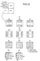
- Processing of coefficients within a subband may be performed in any of the orders shown in Fig. 12.
- the subband is horizontally scanned from above left to below right (part designated by (1) of Fig. 12) or vertically scanned from above left to below right (part (2) of Fig. 12) or scanned spirally from the center of the subband to the outside thereof (part (3) of Fig. 12).
- coefficients in a subband are processed by one scanning as shown in each part (a) of parts (1) to (3) and coefficients in a subband are processed by scanning twice as shown in each parts (b) and (c) of the parts (1) to (3) respectively.
- each arrow shows a coefficient or a set of plural (t) coefficients.
- a set of (t) coefficients is transferred in the direction indicated by the arrow, a subsequent set of (t) coefficients is not transferred and a further subsequent set of (t) coefficients is transferred in the direction indicated by the arrow.
- These steps are repeated in the first scanning process.
- the coefficients left not-transferred in the first scanning process (shown as arrows with real lines) are transferred in the second scanning process (shown as arrows with broken lines) in the similar way as in the first scanning process.
- the first scan in case of part (1) in Fig. 12 encodes coefficients, as shown part (4) in Fig. 12 at the positions of (0, 0), (0, DX), (0, 2*DX) ... ; the second scan encodes coefficients at the positions (0, 1), (0, DX+1), (0, 2*DX+1) ... ; the third scan encodes coefficients at the positions (0, 2), (0, DX+2)...(0, 2*DX+2) ...
- the subband coefficients encoded by scanning at intervals provided between the respective coefficients can reproduce an image whose content can be recognized at an earlier stage of decoding and which image can give better subjective impression by the effect of gradually improving the quality of the decoded image.
- FIG. 13 shows another transmitting order of coefficients of the subband image of Fig. 9.
- three subbands (1, 2, 3) shown in the part (a) of Fig. 13 correspond to one element set in an integrated component unit.
- these three subbands are treated as one element, three coefficients having the same relative positions in respective three subbands are treated as one set as shown in a part (c) of Fig. 13.
- coefficient Y 4 Three coefficients existing at the same relative positions in the respective three subbands in Fig. 13 are supposed as one coefficient, i.e., a (coefficient Y HL1 , coefficient Y LH1 , coefficient Y HH1 ) are represented by a (coefficient Y 4 ).
- the component Y in each of the layers shown in the part (b) of Fig. 13 is transferred first in the scanning order shown in Fig. 12.
- the component U is transferred next and the component V is then transferred.
- Coefficients of subband images of the same resolution levels in horizontal, vertical and diagonal directions are transmitted together from the coding side, so the resolutions of a reproduced image in horizontal, vertical and diagonal directions are increased at a time at the decoding side.
- a subband 1 is first transmitted completely, a subband 2 is then transmitted completely and a subband 3 is finally transmitted.
- the subband 1 of the component Y is transmitted in the scanning order shown in Fig. 12.
- the subband 2 of the component Y is transmitted in the same scanning order and then the subband 3 of the component Y is transmitted in the same scanning order.
- the subbands 1, 2 and 3 of the component U are transmitted one by one in the same scanning order as that for the component Y.
- the subbands 1, 2 and 3 of the components V are transmitted one by one in the same scanning order as that for the component Y.
- An integrated component unit includes elements (the subband 1 of the component Y, the subband 2 of the component Y, the subband 3 of the component Y, the subband 1 of the component U, the subband 2 of the component U, the subband 3 of the component U, the subband 1 of the component V, the subband 2 of the component V, the subband 3 of the component V).
- resolution of an image reproduced at a decoding side is increased in a horizontal direction, vertical direction and diagonal direction in the described order. Transmission of these three subbands in the order of subband 2, subband 1 and subband 3 causes an increase in resolution of the image in the horizontal, vertical and diagonal directions in the described order at the decoding side.
- transmitting subband coefficients may be selectably used. If a codable image is known to be of higher resolution in a specified direction, coefficients of a subband in the known high-resolution direction are transferred first at the coding side and the transferring order is rearranged at the decoding side to earlier reproduce the coefficients of the subband image in the known high-resolution direction. This makes it possible to increase the quality of images in the decoding process at the decoding side. In this instance, it is necessary to inform the decoding side of the transmitting order in which coefficients are encoded by placing such information in the coded data.
- the above-mentioned embodiment treats all coefficients in a subband as one group, it may also prepare an integrated component unit by using a coefficient or a plurality of coefficients in a subband as a group.
- the following example treats one line in a subband as a group of coefficients.
- Fig. 14 shows an integrated component unit consisting of horizontal lines one in each of the subbands, which is expressed as follows:
- an integrated component unit consists of horizontal lines one in each of the subbands, which corresponds to the scanning order shown in the part (a) of part (1) of Fig. 12.
- an integrated component unit composed of vertical lines one in each of the subbands as shown in the part (a) of part (2) of Fig. 12.
- components Y, U, V may be expressed each by one arrow. This processing is done on all subbands in the order shown in Fig. 10, Fig. 11 or the part (b) of Fig. 13.
- Fig. 15 is a flow chart depicting an example of the operation of the transmitting order deciding and rearranging portion 104 of Fig. 7.
- the integrated component unit may be changed over from the subbands to coefficients (one or more groups of coefficient) or vice versa.
- the portion may be designed to operate by using only one of the two units.
- the video coding device can prepare coded data having a hierarchical structure by decomposing an input image composed of a plurality of components Y, U and V into subband images and encoding the subband images in an ascending order of their resolution starting from the lowest-resolution subband.
- the first embodiment of the present invention can perform adaptive encoding of input video data in view of the data characteristics by applying integrated component units according to subband-based and/or coefficient-based integration of the components Y, U and V.
- This video decoding device is intended to decode video data prepared by the video coding device according to the first embodiment of the present invention.
- the video-decoding device comprises a variable-length decoding portion (variable-length decoding means) 201, a decoded-data counting portion (decoded data counting means) 202, a decoding truncating portion (decoding truncating means) 203, a data completing portion (data completing means) 205, a coefficient decoding portion (coefficient decoding means) 206 and a subband synthesizing portion (subband synthesizing means) 207.
- variable-length decoding portion 2101 a decoded data counting portion 2102, a decoding truncating portion 2103, a data completing portion 2105, a coefficient decoding portion 2106 and a subband synthesizing portion 2107, respectively, of Fig. 4.
- numeral 204 designates a component separating portion (component separating means, arranging means) for separating coefficient-coded data rearranged by the transfer-order deciding and rearranging portion of the coding device into data for respective components.
- the component separating portion 204 rearranges coded data into respective component groups Y, U and V by reversing the procedure performed by the coding side.
- the component separating portion 204 has a memory (not shown) for storing respective components Y, U and V.
- This memory has basically the same capacity that the subband decomposing portion 101 of the video coding device has.
- this portion 204 may be designed to separate an integrated component unit into coefficients for respective component groups Y, U, V and output the separated coefficients to the coefficient decoding portion 206 on completion of separation of the integrated component unit.
- the portion may have sufficient memory to store the largest integrated-component unit only.
- the component separating portion 204 may also be designed to work by successively separating and outputting coefficients of an integrated component unit to the coefficient decoding portion 206.
- the component separating portion 204 may have a memory large enough to store a plurality of separated coefficients irrespective of the size of any integrated component unit to be separated.
- the separated coefficients outputted from the component separating portion 204 are decoded by the coefficient decoding portion 206 and then stored in a memory (not shown) of the coefficient decoding portion 206.
- the coefficient decoding portion 206 includes decoded-data arranging means.
- the coefficients separated by the component separating portion 204 may be stored in a variety of memory means.
- the component separating portion 204 separates integrated component units by writing separated coefficients in its memory having the same capacity as has the memory of the subband decomposing portion 101 of the video coding device.
- an integrated component unit composed of subband data (Y 1 ,U 1 ,V 3 ) is decomposed into separate elements Y 1 , U 1 and V 1 respectively.
- the separated elements Y 1 , U 1 , and V 1 are written into corresponding subbands positions in a memory.
- a unit (Y 2 , Y 2 , V 2 ) is decomposed into separate elements Y 2 , U 2 and V 2 that are then written in specified positions of the corresponding subbands in the memory for storing Y, U and V. This processing is done on all the subbands.
- the order of decoding coefficients in each subband is the same as described for the process shown in Fig. 12.
- the coding side performed scans as shown in the part (1) of Fig. 12, so the decoding side must do scans as shown in the part (1) of Fig. 12.
- the application of this scanning method causes an image in the decoding process to have resolution increasing in the order of raster scanning from the top left to the down right.
- an image being decoded can be easily recognized at an earlier stage of decoding as compared with the raster scanned image.
- the image may be gradually improved in resolution level, so the image may have better subjective-image quality.
- the operation of the component separating portion 204 when processing an integrated component unit composed of one or more groups (sets) of coefficients in subbands is as follows:
- Y i (y), U i (y), V i (y) are separated from each other and written in positions ⁇ line y> of the corresponding subbands i in the memory for storing Y, U and V. This processing is done on all the lines in the subbands in the order from the lowest-resolution subband to the highest-resolution subband.
- Elements Y i (y, x), U i (y, x), V i (y, x) are separated from each other and written in positions (y, x) of a coefficient of the corresponding subbands i in the memory for storing Y, U and V. This processing is done on all the coefficients in the subbands from the lowest-resolution subband to the highest-resolution subband.
- the decoding side applies the same coefficient-scanning method as the coding side used even if an integrated component unit is selected by 1 line or by one coefficient.
- the separate coefficients outputted from the component separating portion 204 are combined into respective component groups Y, U and V and then treated as respective groups.
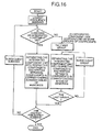
- Fig. 16 is a flow chart depicting an exemplified operation procedure of the component separating portion 204.
- the integrated component unit may be changed over from the subbands to coefficients (one or more groups of coefficient) or vice versa.
- the portion 204 may be provided with either one of the two integrated component units.
- an integrated component unit is composed of one-line data in a subband.
- Data completing portion 205 produces subband coefficients by putting 0 in remaining vacant parts where no data exist. This enables the coefficient decoding portion 206 and the subband synthesizing portion 207 to normally perform subsequent processing steps. Vacant data may also be replaced with any other value than 0.
- the provision of the decoded data counting portion 202, the decoding truncating portion 203 and the data completing portion 205 enables the decoding side to truncate the decoding operation at any position by user's request.
- the data completing portion 205 does nothing while the number of bits of the decoded data does not exceed the threshold value. Accordingly, a maximally expressible value may be previously set as the threshold value in case of decoding all the coded data.
- the embodiment may be a system of Fig. 8, which in this instance omits the decoded data counting portion 202, the decoding truncating portion 203, the data completing portion 205.
- the coded data of the hierarchical structure which represents an image composed of a plurality of components Y, U, V, can be decoded at the decoding side.
- the coded data of the hierarchical structure allows the progressive decoding the coded data, whereby the quality of the entire reproduced image is sequentially improved.
- the present invention enables the system to conduct a variety of progressive reproduction of the coded image.
- the present invention method can uniformly improve the resolution of the reproduced image in horizontal, vertical and diagonal directions, whereas the prior art method only improves the image resolution in the horizontal direction before the other directions.
- a second embodiment of the present invention for coding and decoding an image composed of components having different sizes is described below.
- the second embodiment of the present invention is similar in construction to the first embodiment except for the operation of the transfer-order deciding and rearranging portion 104 (step of outputting an integrated component unit). Therefore, the same portions as the first embodiment are not explained further. Only the transfer-order deciding and rearranging portion 104 will be described below.
- a format of 4:2:0 in which components U and V have a horizontal and vertical size being one-half that of the component Y is used.
- Fig. 17 shows resultants of three times of band-decomposition of each of the component Y whose size is Y*X and the components U and V whose respective size is Y/2*X/2.
- the subbands U and V are each half the size of the component Y in horizontal and vertical directions. Respective components Y, U and V have the same number of subbands.
- the subbands Y, U, V are different in size to each other, so the large-sized component Y may have excess coefficients if an integrated component unit is composed of the same number of coefficients per subband as described before in the first embodiment of the present invention. Therefore, the number of coefficients per component to be included in an integrated component unit is set according to the size ratio of respective components if the components are different from each other in size.
- FIG. 18 shows the correspondance of coefficients of respective components for an image in the format of 4:2:0 as shown in Fig.17.
- the order of transferring the integrated component units is the same as shown in Fig. 10 for the first embodiment of the present invention.
- the ratio of the horizontal and vertical lengths of the components Y, U and V is of 2: 1: 1, so one coefficient of each component U or V corresponds to 4 coefficients of the component Y. Accordingly, the numbers of coefficients for the components Y, U, V to be included in an integrated component unit is determined according to the ratio of 4: 1: 1.
- the integrated component units prepared on the basis of the subbands of respective components contain coefficients of the components Y, U and V at the ratio of 4:1:1 and are processed in the same manner as described before for the first embodiment of the present invention.
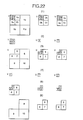
- an integrated component unit for one line per subband is prepared to contain two lines Y, one line U and one line V as shown in Fig. 19 while an integrated component unit for a coefficient group per subband is prepared to contain 2*2 coefficients Y, one coefficient U and one coefficient V as shown in Fig. 20.
- numerals suffixed one to component data Y, U and V indicate, by way of example, the order of transferring the data within the respective integrated component units.
- the integrated component units for Y, U and V are processed one by one for one subband. On completion of processing one subband, the process advances to processing another subband in the order shown in the part (1) of Fig. 18.
- the order of transferring the subbands may be either one of those shown in Figs. 11 and the part (b) of Fig. 13.
- the video decoding side can decode the coded data transmitted from the coding side by changing the numbers of data of components contained in an integrated component unit according to the ratio of horizontal and vertical sizes of the components and writing the data in the corresponding positions in a memory.
- the second embodiment of the present invention is similar in construction and function to the first embodiment except for the operation of the transfer-order deciding and rearranging portion 204 (step of separating an integrated component unit into respective components and writing separated data in corresponding subbands in a memory). Therefore, the further description is omitted.
- the decoding side can decode entire decoded data and can also obtain an entire reproduced image from a part of the coded data.
- a third embodiment of the present invention is adaptable to the case of processing image components being different in size and decomposed into different numbers of decomposition levels by the subband decomposing portion 101 of Fig. 7.
- This embodiment of the present invention is similar to the first embodiment except for the operation of the transfer-order deciding and rearranging portion 104 (step of outputting an integrated component unit). Therefore, the same portions are not explained further. Only the transfer-order deciding and rearranging portion 104 will be described below.
- this embodiment is described by way of example with an input image whose components U and V have horizontal and vertical lengths being one half of those of the component Y.
- a part designated by (1) of Fig. 21 shows the results of decomposing the component Y three times and the components U and V twice respectively.
- the third embodiment cannot use the transferring methods described for the first and second embodiments and so uses the following method of transferring the subbands.
- the transferring order is expressed as (Y 1 ,U 1 ,V 1 ),(Y 2 ,U 2 ,V 2 ),...,(Y 7 ,U 7 ,V 7 ),(Y 8 ),(Y 9 ),(Y 10 ).
- FIG. 22 Another example (second example) is shown in Fig. 22.
- the subband images shown in a part (1) of Fig. 22 are obtained as the result of decomposing the component Y three times and the components U and V twice respectively.
- integrated component units to be transmitted are formed by combining a set of four low-resolution subbands Y with two low-resolution subbands U and V as shown in a part (2) of Fig. 22 and by combining high-resolution subbands of the components Y, U and V with each other by ones as shown in a part (3) of Fig. 22.
- the order of transferring the subbands is as follows: (Y 1 , Y 2 , Y 3 , Y 4 , U 1 , V 1 ), (Y 5 , U 2 , V 2 ), (Y 6 , U 3 , V 3 ), (Y 7 , U 4 , V 4 ), (Y 8 , U 5 , V 5 ), (Y 9 , U 6 , V 6 ), (Y 10 , U 7 , V 7 ).
- Subbands (Y 5 , Y 6 , Y 7 ) shown in the part (3) of Fig. 22 correspond to a vertical-resolution subband, a horizontal-resolution subband and a diagonal-resolution subband respectively and have the same resolution levels. Therefore, each integrated component unit can be prepared by combining respective high-resolution subbands of respective components Y, U and V by threes for each component. This is the third example of preparing an integrated component unit. Similarly, an integrated component unit may be prepared of combinations (Y 8 , Y 9 , Y 10 ), (U 2 , U 3 , U 4 ), (U 5 , U 6 , U 7 ), (V 2 , V 3 , V 4 ), (V 5 , V 6 , V 7 ).
- the transmitting order is as follows: (Y 1 , Y 2 , Y 3 , Y 4 , U 1 , V 1 ), (Y 5 , Y 6 , Y 7 , U 2 , U 3 , U 4 , V 2 , V 3 , V 4 ), (Y 8 , Y 9 , Y 10 , U 5 , U 6 , U 7 , V 5 , V 6 , V 7 ).
- subbands Y 1 , Y 2 , Y 3 , Y 4 , U 1 , V are selected as a plurality of low-resolution subbands with keeping the size ratio of Y, U and V (in this example, the horizontal and vertical size ratio is 2:1:1).
- Y 1 , Y 2 ,..., Y 7 , U 1 , ..., U 4 , V 1 ..., V 4 may also be selected as a plurality of the low-resolution subbands.
- a further fourth example which is another variety of above-mentioned second or third example is such that the lowest resolution subbands Y, U, Vare extracted from respective groups of low-resolution subbands Y 1 , Y 2 ,..., Y 7 , U 1 , ..., U 4 , V 1 ..., V 4 for respective components and separately transferred as shown in a part (4) of Fig. 22 and a set of remaining low-resolution subbands is then transferred as in the second or third example.
- the set of the low-resolution subbands is a combination of six Y-component subbands, three U-component subbands and three V-component subbands as shown in a part (5) of Fig. 22. After transmission of all the low-resolution subbands, high-resolution subbands shown in a part (6) of Fig. 22 are transferred.
- the order of transferring the subbands is as follows: (Y 1 , U 1 , V 1 ), (Y 2 , Y 3 , Y 4 , Y 5 , U 2 , V 2 ), (Y 5 , U 3 , V 3 ), (Y 7 , U 4 , V 4 ), (Y 8 , U 5 , V 5 ), (Y 9 , U 6 , V 6 ), (Y 10 , U 7 , V 7 ).
- the order of transferring the subbands is as follows: (Y 1 , U 1 , V 1 ), (Y 2 , Y 3 , Y 4 , Y 5 , Y 6 , Y 7 , U 2 , U 3 , U 4 , V 2 , V 3 , V 4 ), (Y 8 , Y 9 , Y 10 , U 5 , U 6 , U 7 , V 5 , V 6 , V 7 ).
- subbands having resolution levels higher than that of a subband shown in a part (6) of Fig. 22 are the same in quantity for components Y, U and V.
- integrated component units composed each of a combination of the same number of subbands Y, U, V are subsequently transmitted.
- the transmitting order of the three subbands which have the same resolution levels in horizontal, vertical and diagonal directions shall not be restricted.
- the transmitting order of these three subbands may be not only subband1, subband2, subband3, but also subband2, subband1, subband3, for example.
- the video decoding side can decode the coded data received from the coding side by separating components in each integrated component unit into groups of respective components Y, U and V, writing separated data in the corresponding subband areas in the memory and finally writing three highest-resolution subbands in the corresponding subband area of the memory.
- the video decoding side can decode the coded data received from the coding side by separating the subbands in each integrated component unit by reversing the process made by the coding side and writing the subbands of each component in the corresponding subband area in the corresponding memory.
- the third embodiment differs from the first and second embodiments by the fact that only the first integrated component unit is prepared from a plurality of the low-resolution subbands by the coding side and contains four subbands Y, one subband U and one subband V.
- an initial integrated-component unit may contain seven Y-component subbands, four U-component subbands and four V-component subbands.
- each integrated component unit can be decomposed into subbands of respective components Y, U and V by the same method as described for the second example and written into corresponding subband areas (for Y, U and V components) in the memory for decoding them. Since the high-resolution subbands Y, U and V have been combined by threes in an integrated component unit at the coding side, the high-resolution subbands Y, U and V are recorded by threes for each component in corresponding subband areas in the memory for decoding them.
- This example differs from the second example by the above-mentioned feature.
- the video decoding side can decode the coded data received from the coding side by separating the subbands in each integrated component unit in the same manner as shown for decoding device in second or third example and writing the subbands of each component in the corresponding subband area in the corresponding memory.
- This example differs from the second and third examples by the fact that the lowest-resolution subbands of the respective components Y, U, V are first stored in the corresponding subband areas (Y, U, V) in the memory for decoding and then low-resolution subbands other than the lowest-resolution subbands are stored in the corresponding areas (Y, U, V) in the memory.
- the video decoding device is similar to that of the first embodiment except for the operation of the component separating portion 204 (step of separating each integrated component unit into respective components and writing the separated data in the corresponding areas in a memory). Therefore, further explanation is omitted.
- the third embodiment can apply the same process as described before with the same case in the first and second embodiments based upon the same method as described for the integrated component unit composed the subbands for the respective components Y, U and V.
- an image whose components have different sizes and different decomposition levels can be encoded so that coded data having a hierarchical structure is obtained at the coding side and an entire image is reproduced from the entire coded data or a part of the coded data at the decoding side.
- the third embodiment has been described by way of example with only an image having components whose size ratio is of 2:1:1, it can treat other size ratios of image components in the similar manner as described above.
- an image whose components Y, U and V are the same in size and have different numbers of subbands can be encoded to have a hierarchical structure through the same process as described above in the third embodiment.
- the transmitting orders corresponding to those shown in Figs. 11 and 13 are also adopted besides the described order of Fig. 10.
- the present invention brings following advantageous effects.
- the video coding device and the video decoding device according to the present invention operate with integrated component units whose elements are all frequency coefficients in m (m ⁇ 1) respective subbands of respective component A n and can therefore transmit and decoded first specified subbands of the image components that may be components Y, U and V and have different levels of influence on human visual property, allowing one to recognize an essence of the image at an earlier stage of decoding at the decoding side.
- the coding device can transmit first coded coefficients of higher-resolution-direction subbands and the decoding device can decode those coded coefficients, terminate the decoding in the midway of decoding all coded data and reproduce the image from only data decoded till that time to improve subjective-image quality of the image.
- the video coding device and the video decoding device operate with integrated component units whose elements are m (m ⁇ 1) pieces of frequency coefficients having the same relative positions in m (m ⁇ 1) respective subbands of respective components A n and can decode those coded coefficients, terminate the decoding in the midway of decoding all the coded data and reproduce the image from only the data decoded till that time to improve subjective-image quality of the image when the image is composed of components R, G and B that have substantially almost the same influence on human visual property.
- the video coding device and the video decoding device according to the present invention can be adapted to process an image whose luminance and chrominance components are different from each other by resolution, having a great advantage over the conventional method that can be applied to an image whose components have the same resolution.
- This feature provided by the present invention is very desirable in particular to digital image processing since many digital images are usually formatted to have higher resolution of the luminance component than that of chrominance component.
Landscapes
- Engineering & Computer Science (AREA)
- Multimedia (AREA)
- Signal Processing (AREA)
- Compression Or Coding Systems Of Tv Signals (AREA)
- Color Television Systems (AREA)
- Compression Of Band Width Or Redundancy In Fax (AREA)
Applications Claiming Priority (5)
| Application Number | Priority Date | Filing Date | Title |
|---|---|---|---|
| JP13959197 | 1997-05-29 | ||
| JP13959197 | 1997-05-29 | ||
| JP12693898 | 1998-05-11 | ||
| JP12693898A JP3213582B2 (ja) | 1997-05-29 | 1998-05-11 | 画像符号化装置及び画像復号装置 |
| EP19980921855 EP1016284B1 (fr) | 1997-05-29 | 1998-05-28 | Dispositifs de codage et de decodage video |
Related Parent Applications (1)
| Application Number | Title | Priority Date | Filing Date |
|---|---|---|---|
| EP19980921855 Division EP1016284B1 (fr) | 1997-05-29 | 1998-05-28 | Dispositifs de codage et de decodage video |
Publications (2)
| Publication Number | Publication Date |
|---|---|
| EP1355497A2 true EP1355497A2 (fr) | 2003-10-22 |
| EP1355497A3 EP1355497A3 (fr) | 2004-05-19 |
Family
ID=26463014
Family Applications (2)
| Application Number | Title | Priority Date | Filing Date |
|---|---|---|---|
| EP19980921855 Expired - Lifetime EP1016284B1 (fr) | 1997-05-29 | 1998-05-28 | Dispositifs de codage et de decodage video |
| EP20030011993 Withdrawn EP1355497A3 (fr) | 1997-05-29 | 1998-05-28 | Appareil de codage et décodage de séquences vidéo |
Family Applications Before (1)
| Application Number | Title | Priority Date | Filing Date |
|---|---|---|---|
| EP19980921855 Expired - Lifetime EP1016284B1 (fr) | 1997-05-29 | 1998-05-28 | Dispositifs de codage et de decodage video |
Country Status (5)
| Country | Link |
|---|---|
| US (3) | US6259735B1 (fr) |
| EP (2) | EP1016284B1 (fr) |
| JP (1) | JP3213582B2 (fr) |
| DE (1) | DE69818850T2 (fr) |
| WO (1) | WO1998054903A1 (fr) |
Families Citing this family (41)
| Publication number | Priority date | Publication date | Assignee | Title |
|---|---|---|---|---|
| JP3224514B2 (ja) * | 1996-08-21 | 2001-10-29 | シャープ株式会社 | 動画像符号化装置および動画像復号装置 |
| SE513353C2 (sv) * | 1998-10-21 | 2000-08-28 | Ericsson Telefon Ab L M | Partiell hämtning av bilder i den komprimerade domänen |
| US6546143B1 (en) * | 1999-03-12 | 2003-04-08 | Hewlett-Packard Development Company | Efficient wavelet-based compression of large images |
| EP1166565B1 (fr) * | 1999-03-26 | 2004-08-04 | Microsoft Corporation | Codage d'image par reorganisation de coefficients d'ondelettes |
| US6678419B1 (en) | 1999-03-26 | 2004-01-13 | Microsoft Corporation | Reordering wavelet coefficients for improved encoding |
| US6477280B1 (en) * | 1999-03-26 | 2002-11-05 | Microsoft Corporation | Lossless adaptive encoding of finite alphabet data |
| US6850649B1 (en) | 1999-03-26 | 2005-02-01 | Microsoft Corporation | Image encoding using reordering and blocking of wavelet coefficients combined with adaptive encoding |
| GB9919805D0 (en) * | 1999-08-21 | 1999-10-27 | Univ Manchester | Video cording |
| JP4367880B2 (ja) * | 1999-12-09 | 2009-11-18 | キヤノン株式会社 | 画像処理装置及びその方法並びに記憶媒体 |
| US6771828B1 (en) | 2000-03-03 | 2004-08-03 | Microsoft Corporation | System and method for progessively transform coding digital data |
| KR20020026175A (ko) * | 2000-04-04 | 2002-04-06 | 요트.게.아. 롤페즈 | 웨이브릿 변환을 이용한 비디오 인코딩 방법 |
| JP2002016925A (ja) * | 2000-04-27 | 2002-01-18 | Canon Inc | 符号化装置及び符号化方法 |
| DE10022262A1 (de) * | 2000-05-08 | 2001-12-06 | Siemens Ag | Verfahren und eine Anordnung zur Codierung bzw. Decodierung einer Folge von Bildern |
| KR100353851B1 (ko) | 2000-07-07 | 2002-09-28 | 한국전자통신연구원 | 파문 스캔 장치 및 그 방법과 그를 이용한 영상코딩/디코딩 장치 및 그 방법 |
| KR100574536B1 (ko) | 2000-11-30 | 2006-04-27 | 캐논 가부시끼가이샤 | 화상처리장치, 화상처리방법, 기억매체 및 프로그램 |
| EP1339018B1 (fr) | 2000-11-30 | 2008-12-17 | Canon Kabushiki Kaisha | Dispositif de traitement d'image, procede de traitement d'image, support d'enregistrement et programme correspondant |
| US7192615B2 (en) * | 2001-02-28 | 2007-03-20 | J&J Consumer Companies, Inc. | Compositions containing legume products |
| AUPR433901A0 (en) * | 2001-04-10 | 2001-05-17 | Lake Technology Limited | High frequency signal construction method |
| JP4669645B2 (ja) * | 2001-09-21 | 2011-04-13 | 株式会社リコー | 画像符号化装置、画像符号化方法、プログラム、及び記録媒体 |
| US7447631B2 (en) * | 2002-06-17 | 2008-11-04 | Dolby Laboratories Licensing Corporation | Audio coding system using spectral hole filling |
| JP3679083B2 (ja) * | 2002-10-08 | 2005-08-03 | 株式会社エヌ・ティ・ティ・ドコモ | 画像符号化方法、画像復号方法、画像符号化装置、画像復号装置、画像符号化プログラム、画像復号プログラム |
| JP4371982B2 (ja) * | 2004-11-08 | 2009-11-25 | キヤノン株式会社 | 画像処理装置及びその制御方法、並びに、コンピュータプログラム及びコンピュータ可読記憶媒体 |
| TW200746655A (en) * | 2005-11-18 | 2007-12-16 | Sony Corp | Encoding device and method, decoding device and method, and transmission system |
| CN101138248A (zh) * | 2005-12-07 | 2008-03-05 | 索尼株式会社 | 编码装置、编码方法、编码程序、解码装置、解码方法和解码程序 |
| US8665943B2 (en) * | 2005-12-07 | 2014-03-04 | Sony Corporation | Encoding device, encoding method, encoding program, decoding device, decoding method, and decoding program |
| EP2051499B1 (fr) * | 2006-07-13 | 2015-09-09 | NEC Corporation | Dispositif de codage et de décodage, procédé de codage et procédé de décodage d'images par ondelettes |
| JP4129694B2 (ja) * | 2006-07-19 | 2008-08-06 | ソニー株式会社 | 情報処理装置および方法、プログラム、並びに記録媒体 |
| JP4240331B2 (ja) * | 2006-11-02 | 2009-03-18 | ソニー株式会社 | 送信装置および方法、プログラム、並びに通信システム |
| JP4254867B2 (ja) * | 2007-01-31 | 2009-04-15 | ソニー株式会社 | 情報処理装置および方法、プログラム、並びに記録媒体 |
| US20100166053A1 (en) * | 2007-01-31 | 2010-07-01 | Sony Corporation | Information processing device and method |
| JP4254866B2 (ja) * | 2007-01-31 | 2009-04-15 | ソニー株式会社 | 情報処理装置および方法、プログラム、並びに記録媒体 |
| JP5162939B2 (ja) * | 2007-03-30 | 2013-03-13 | ソニー株式会社 | 情報処理装置および方法、並びにプログラム |
| RU2479937C2 (ru) | 2007-03-30 | 2013-04-20 | Сони Корпорейшн | Устройство и способ обработки информации |
| JP4488027B2 (ja) | 2007-05-17 | 2010-06-23 | ソニー株式会社 | 情報処理装置および方法、並びに、情報処理システム |
| US8260068B2 (en) * | 2007-05-17 | 2012-09-04 | Sony Corporation | Encoding and decoding device and associated methodology for obtaining a decoded image with low delay |
| US8515181B2 (en) | 2009-02-11 | 2013-08-20 | Ecole De Technologie Superieure | Method and system for determining a quality measure for an image using a variable number of multi-level decompositions |
| US8326046B2 (en) | 2009-02-11 | 2012-12-04 | Ecole De Technologie Superieure | Method and system for determining structural similarity between images |
| US8515182B2 (en) | 2009-02-11 | 2013-08-20 | Ecole De Technologie Superieure | Method and system for determining a quality measure for an image using multi-level decomposition of images |
| JP5263621B2 (ja) * | 2009-09-24 | 2013-08-14 | ソニー株式会社 | 画像処理装置および方法 |
| EP2462913A1 (fr) | 2010-12-10 | 2012-06-13 | Fresenius Medical Care Deutschland GmbH | Insert et flacon pour l'infusion de liquides |
| US8983206B2 (en) | 2011-05-04 | 2015-03-17 | Ecole de Techbologie Superieure | Method and system for increasing robustness of visual quality metrics using spatial shifting |
Citations (1)
| Publication number | Priority date | Publication date | Assignee | Title |
|---|---|---|---|---|
| JPH08242379A (ja) | 1994-12-05 | 1996-09-17 | Microsoft Corp | 離散ウエーブレット変換を用いた漸進的画像伝送方法及びそのためのデータ・ファイル |
Family Cites Families (5)
| Publication number | Priority date | Publication date | Assignee | Title |
|---|---|---|---|---|
| US4827336A (en) | 1987-12-18 | 1989-05-02 | General Electric Company | Symbol code generation processing from interframe DPCM of TDM'd spatial-frequency analyses of video signals |
| GB2258781B (en) * | 1991-08-13 | 1995-05-03 | Sony Broadcast & Communication | Data compression |
| JPH0638198A (ja) * | 1992-05-19 | 1994-02-10 | Sony Corp | 画像信号伝送装置及び画像信号伝送方法 |
| GB2268667B (en) * | 1992-06-24 | 1995-11-08 | Sony Broadcast & Communication | Serial data decoding |
| EP1635579A2 (fr) * | 1995-09-12 | 2006-03-15 | Matsushita Electric Industrial Co., Ltd. | Méthode de codage et dispositif de transformation à ondelettes |
-
1998
- 1998-05-11 JP JP12693898A patent/JP3213582B2/ja not_active Expired - Lifetime
- 1998-05-28 WO PCT/JP1998/002349 patent/WO1998054903A1/fr not_active Ceased
- 1998-05-28 EP EP19980921855 patent/EP1016284B1/fr not_active Expired - Lifetime
- 1998-05-28 DE DE1998618850 patent/DE69818850T2/de not_active Expired - Lifetime
- 1998-05-28 US US09/381,029 patent/US6259735B1/en not_active Expired - Lifetime
- 1998-05-28 EP EP20030011993 patent/EP1355497A3/fr not_active Withdrawn
-
2001
- 2001-06-07 US US09/875,098 patent/US6813314B2/en not_active Expired - Fee Related
-
2004
- 2004-07-08 US US10/885,805 patent/US20050025239A1/en not_active Abandoned
Patent Citations (1)
| Publication number | Priority date | Publication date | Assignee | Title |
|---|---|---|---|---|
| JPH08242379A (ja) | 1994-12-05 | 1996-09-17 | Microsoft Corp | 離散ウエーブレット変換を用いた漸進的画像伝送方法及びそのためのデータ・ファイル |
Non-Patent Citations (1)
| Title |
|---|
| FUJII, NOUMURA: "Topics on Wavelet Transform", REPORT OF "TECHNICAL REPORT OF IEICE, IE92-11, 1992 |
Also Published As
| Publication number | Publication date |
|---|---|
| EP1016284A1 (fr) | 2000-07-05 |
| US6259735B1 (en) | 2001-07-10 |
| US20020009142A1 (en) | 2002-01-24 |
| DE69818850T2 (de) | 2004-08-19 |
| EP1016284B1 (fr) | 2003-10-08 |
| JP3213582B2 (ja) | 2001-10-02 |
| EP1355497A3 (fr) | 2004-05-19 |
| US6813314B2 (en) | 2004-11-02 |
| DE69818850D1 (de) | 2003-11-13 |
| JPH1146372A (ja) | 1999-02-16 |
| WO1998054903A1 (fr) | 1998-12-03 |
| US20050025239A1 (en) | 2005-02-03 |
Similar Documents
| Publication | Publication Date | Title |
|---|---|---|
| EP1016284B1 (fr) | Dispositifs de codage et de decodage video | |
| Marcellin et al. | An overview of JPEG-2000 | |
| KR100880039B1 (ko) | 웨이블릿 기반 이미지 코덱에서의 부호화 이득을 달성하는방법 및 시스템 | |
| JP4367880B2 (ja) | 画像処理装置及びその方法並びに記憶媒体 | |
| JP3534465B2 (ja) | サブバンド符号化方法 | |
| US6101284A (en) | Methods and systems for optimizing image data compression involving wavelet transform | |
| EP0734164B1 (fr) | Procédé et appareil pour le codage du signal vidéo avec un dispositif de classification | |
| JPH08186815A (ja) | サブバンド符号化方法 | |
| US6993199B2 (en) | Method and system for improving coding efficiency in image codecs | |
| JP2000341693A (ja) | デジタル信号変換方法及び装置 | |
| US20020171743A1 (en) | Electronic device and digital still camera | |
| Cosman et al. | Memory constrained wavelet based image coding | |
| JP3213561B2 (ja) | 画像符号化装置及び画像復号装置 | |
| US7065252B1 (en) | System and method providing improved data compression via wavelet coefficient encoding | |
| US6847736B2 (en) | In image compression, selecting field or frame discrete wavelet transformation based on entropy, power, or variances from the high frequency subbands | |
| JP2980218B2 (ja) | 画像情報符号化装置及び画像情報復号化装置 | |
| JP3704644B2 (ja) | 画像符号化装置及びその方法並びに画像復号化装置及びその方法 | |
| JP2001197498A (ja) | 画像処理装置及び方法及び記憶媒体 | |
| JP2003244443A (ja) | 画像符号化装置及び画像復号装置 | |
| JPH0779350A (ja) | 画像データ圧縮処理方法および画像データ再構成方法 | |
| JP4174254B2 (ja) | 動画像符号化装置及び動画像復号装置並びにそれらの方法 | |
| JP2001045482A (ja) | 画像処理装置及び方法 | |
| EP0848557A2 (fr) | Méthode de codage d'image par sous bandes | |
| JP3032281B2 (ja) | 画像符号化方法及び画像復号化方法 | |
| PL240833B1 (pl) | System i sposób przetwarzania obrazów zwłaszcza w urządzeniach akwizycji, przetwarzania i składowania lub transmisji przeprowadzających kompresję obrazów cyfrowych z wykorzystaniem dyskretnej transformacji falkowej DWT i kodowania entropijnego |
Legal Events
| Date | Code | Title | Description |
|---|---|---|---|
| PUAI | Public reference made under article 153(3) epc to a published international application that has entered the european phase |
Free format text: ORIGINAL CODE: 0009012 |
|
| AC | Divisional application: reference to earlier application |
Ref document number: 1016284 Country of ref document: EP Kind code of ref document: P |
|
| AK | Designated contracting states |
Kind code of ref document: A2 Designated state(s): DE FR GB IT NL |
|
| RIN1 | Information on inventor provided before grant (corrected) |
Inventor name: KATATA, HIROYUKI Inventor name: AONO, TOMOKO Inventor name: SAIGA, HISASHI Inventor name: KUSAO, HIROSHI |
|
| PUAL | Search report despatched |
Free format text: ORIGINAL CODE: 0009013 |
|
| AK | Designated contracting states |
Kind code of ref document: A3 Designated state(s): DE FR GB IT NL |
|
| RIC1 | Information provided on ipc code assigned before grant |
Ipc: 7H 04N 11/04 B Ipc: 7H 04N 7/26 A |
|
| 17P | Request for examination filed |
Effective date: 20040712 |
|
| AKX | Designation fees paid |
Designated state(s): DE FR GB IT NL |
|
| STAA | Information on the status of an ep patent application or granted ep patent |
Free format text: STATUS: THE APPLICATION IS DEEMED TO BE WITHDRAWN |
|
| 18D | Application deemed to be withdrawn |
Effective date: 20130207 |