EP1356885A2 - Fraise à disque et plaquette de coupe pour une fraise à disque - Google Patents
Fraise à disque et plaquette de coupe pour une fraise à disque Download PDFInfo
- Publication number
- EP1356885A2 EP1356885A2 EP03008321A EP03008321A EP1356885A2 EP 1356885 A2 EP1356885 A2 EP 1356885A2 EP 03008321 A EP03008321 A EP 03008321A EP 03008321 A EP03008321 A EP 03008321A EP 1356885 A2 EP1356885 A2 EP 1356885A2
- Authority
- EP
- European Patent Office
- Prior art keywords
- milling cutter
- cutting
- disk milling
- seat
- insert
- Prior art date
- Legal status (The legal status is an assumption and is not a legal conclusion. Google has not performed a legal analysis and makes no representation as to the accuracy of the status listed.)
- Granted
Links
Images




Classifications
-
- B—PERFORMING OPERATIONS; TRANSPORTING
- B23—MACHINE TOOLS; METAL-WORKING NOT OTHERWISE PROVIDED FOR
- B23C—MILLING
- B23C5/00—Milling-cutters
- B23C5/02—Milling-cutters characterised by the shape of the cutter
- B23C5/08—Disc-type cutters
-
- B—PERFORMING OPERATIONS; TRANSPORTING
- B23—MACHINE TOOLS; METAL-WORKING NOT OTHERWISE PROVIDED FOR
- B23C—MILLING
- B23C5/00—Milling-cutters
- B23C5/16—Milling-cutters characterised by physical features other than shape
- B23C5/20—Milling-cutters characterised by physical features other than shape with removable cutter bits or teeth or cutting inserts
- B23C5/202—Plate-like cutting inserts with special form
-
- B—PERFORMING OPERATIONS; TRANSPORTING
- B23—MACHINE TOOLS; METAL-WORKING NOT OTHERWISE PROVIDED FOR
- B23C—MILLING
- B23C5/00—Milling-cutters
- B23C5/16—Milling-cutters characterised by physical features other than shape
- B23C5/20—Milling-cutters characterised by physical features other than shape with removable cutter bits or teeth or cutting inserts
- B23C5/22—Securing arrangements for bits or teeth or cutting inserts
- B23C5/2204—Securing arrangements for bits or teeth or cutting inserts with cutting inserts clamped against the walls of the recess in the cutter body by a clamping member acting upon the wall of a hole in the insert
-
- B—PERFORMING OPERATIONS; TRANSPORTING
- B23—MACHINE TOOLS; METAL-WORKING NOT OTHERWISE PROVIDED FOR
- B23C—MILLING
- B23C5/00—Milling-cutters
- B23C5/16—Milling-cutters characterised by physical features other than shape
- B23C5/20—Milling-cutters characterised by physical features other than shape with removable cutter bits or teeth or cutting inserts
- B23C5/22—Securing arrangements for bits or teeth or cutting inserts
- B23C5/24—Securing arrangements for bits or teeth or cutting inserts adjustable
- B23C5/2462—Securing arrangements for bits or teeth or cutting inserts adjustable the adjusting means being oblique surfaces
-
- B—PERFORMING OPERATIONS; TRANSPORTING
- B23—MACHINE TOOLS; METAL-WORKING NOT OTHERWISE PROVIDED FOR
- B23C—MILLING
- B23C2200/00—Details of milling cutting inserts
- B23C2200/36—Other features of the milling insert not covered by B23C2200/04 - B23C2200/32
- B23C2200/367—Mounted tangentially, i.e. where the rake face is not the face with largest area
-
- B—PERFORMING OPERATIONS; TRANSPORTING
- B23—MACHINE TOOLS; METAL-WORKING NOT OTHERWISE PROVIDED FOR
- B23C—MILLING
- B23C2215/00—Details of workpieces
- B23C2215/20—Crankshafts
-
- Y—GENERAL TAGGING OF NEW TECHNOLOGICAL DEVELOPMENTS; GENERAL TAGGING OF CROSS-SECTIONAL TECHNOLOGIES SPANNING OVER SEVERAL SECTIONS OF THE IPC; TECHNICAL SUBJECTS COVERED BY FORMER USPC CROSS-REFERENCE ART COLLECTIONS [XRACs] AND DIGESTS
- Y10—TECHNICAL SUBJECTS COVERED BY FORMER USPC
- Y10T—TECHNICAL SUBJECTS COVERED BY FORMER US CLASSIFICATION
- Y10T407/00—Cutters, for shaping
- Y10T407/19—Rotary cutting tool
- Y10T407/1952—Having peripherally spaced teeth
- Y10T407/1962—Specified tooth shape or spacing
-
- Y—GENERAL TAGGING OF NEW TECHNOLOGICAL DEVELOPMENTS; GENERAL TAGGING OF CROSS-SECTIONAL TECHNOLOGIES SPANNING OVER SEVERAL SECTIONS OF THE IPC; TECHNICAL SUBJECTS COVERED BY FORMER USPC CROSS-REFERENCE ART COLLECTIONS [XRACs] AND DIGESTS
- Y10—TECHNICAL SUBJECTS COVERED BY FORMER USPC
- Y10T—TECHNICAL SUBJECTS COVERED BY FORMER US CLASSIFICATION
- Y10T407/00—Cutters, for shaping
- Y10T407/23—Cutters, for shaping including tool having plural alternatively usable cutting edges
Definitions
- the present invention relates to a side milling cutter, in particular for milling crankshafts, and a cutting tip therefor.
- Milling is a machining process in which the tool rotates, with relative movements between workpiece and tool perpendicular to its axis of rotation.
- the tool is equipped with cutting edges that are used when the tool is rotated around the Tool axis generate the cutting movement.
- the feed movements can be in different Directions are done. You can use both the tool and the workpiece or even run by both.
- the cutting edges are different from turning or drilling not constantly engaged with the workpiece. Rather, they are cut to the workpiece returned to the starting point. This has the advantage that the cutting edges can cool and the chips are released from the chip chambers.
- cutting inserts When milling, tools are usually used on which inserts are attached, the have the corresponding cutting edges.
- Such cutting inserts also called cutting inserts have been known in principle for a long time.
- crankshafts are generally understood to mean machine elements with which linear movements be converted into rotating or rotating into linear movements.
- the standard Manufacture of crankshafts is mostly based on forged or cast crankshafts resorted. Modern engine design places increasing demands on performance and the smoothness of crankshafts. In addition, the costs are to be reduced. Are in demand essentially a higher engine output with the same stroke, an improved efficiency, i.e. less friction loss, and less weight. This inevitably requires optimization all construction parameters, such as B. the dimensions, the material properties and the Surface treatments, especially the low surface tolerances. At the same time becomes Reduction of manufacturing costs in the manufacturing machining of crankshafts more and more frequently grinding by machining with a defined cutting edge, e.g. B. turning, turning broaching or milling replaced if possible.
- the milling cutters When finishing milling, the milling cutters are usually with diameter cutting and plunge cutting stocked.
- the diameter cutting edges create the bearing diameter, which will be used in a later operation is still finished, and the plunge cutters produce the finished bearing width, i.e. H. the opposite faces of the thrust collars (also called oil collars) for the connecting rods, and the as a grinding outlet in the transition area between the journal and the mentioned Thrust collars on the radially inner section of the crank webs.
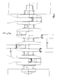
- a crankshaft 5 can be seen as an example in the clamped state.
- the crankshaft 5 has main bearings A, B, C, D and E as well as pin bearings 1, 2, 3, 4.
- the individual pin bearings are in the pendulum lifting method processed by means of the disc milling cutter 6.
- the pendulum lifting method turns during machining the crankshaft around its longitudinal axis.
- the one with the desired cutting speed rotating disc milling cutter 6 are the corresponding movement of the pin bearing 1, 2, 3, 4 tracked.
- the machining of the pin bearings 1, 2, 3, 4 of the crankshaft 5 is essentially ended after each full revolution of the crankshaft 5. Even the peripheral surfaces of the crank webs can be processed in the same operation.
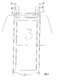
- FIG. 2 the machining of the pin bearing 3 from FIG. 1 is shown enlarged.
- the side milling cutter 6 is here with diameter cutting edges 7, which are arranged cross-toothed, and plunge cutting 8 equipped.
- the diameter cutting edges 7 are arranged tangentially, while the plunge cutting edges 8 are arranged laterally.
- the known laterally arranged puncture blades are as Indexable insert with four cutting edges, which depend on the direction of installation engage the workpiece.
- a cutting insert for camshaft milling cutters has been proposed in WO 01/76796 A1.
- at the cutting edge of the cutting insert has a plurality of cutting edge sections with a first straight section, a second straight section Section that connects to the first section and with this an angle between 90 ° and less than 180 °, and with a third cutting edge portion that is convexly curved runs.
- the convex section forms the cutting edge.
- This camshaft cutter has however also face tolerance in the order of 20 ⁇ m.
- a cutting insert for disc milling cutters in particular for milling crankshafts, solved with an upper and a lower surface and rotating Side surfaces that connect the top and bottom surfaces, the top Surface has at least in the region of two corners, bead-like elevations or projections preferably extend over the entire length of one side of the insert, so that in one Top view of a rake surface formed by at least one of the side surfaces, the edge which defines the transition from the upper surface to the rake surface, in the area of the two ends this edge, each has a projecting section relative to the central edge section.
- the edge profile of the rake face thus consists of a generally indefinable one however, straight middle section and two bulging end sections, which form the actual cutting edges.
- the insert is intended for inclined installation, so that depending on the direction of inclination essentially only a raised or protruding end section engages with the workpiece occurs, which serves as the cutting edge.
- This measure gives one of the rake faces serving side surfaces of the cutting insert two usable cutting edges, and a left and a right one.
- the insert can when engaged with the workpiece trimmed cutting edge is worn, in substantially the same orientation in a different one Installation position, i.e. on the opposite side of the in relation to the previous installation position Side milling cutter can be used again.
- the profile of the raised or projecting section can be according to the desired Profile of the groove serving as a grinding outlet in the transition area between the journal and Crank cheek of a crankshaft can be designed.
- the raised sections therefore advantageously have a convex curvature, the curved section also being able to consist of straight sections which are angled relative to one another, the convexly curved section extending over an angular range of more than 90 °, preferably over an angular range of more than 95 ° and particularly preferably extends over an angular range of approximately 110 ° or more.
- the convex main cutting edge which is formed in the area of a cutting corner essentially by the transition between a side surface and the bead-like elevation on the upper surface, ends in a secondary cutting edge which is formed between the side surfaces adjacent to this cutting corner, one of which is the rake surface and the other defines the secondary open space.
- the rake surface preferably runs out at an obtuse transition angle to the middle section of the edge between the upper surface and the side surface or rake surface, so that the section of the cutting edge lying towards the center, insofar as it still engages the workpiece, at an angle of significantly less than 90 ° inclined to the plane defined by the upper or lower surface. This serves to keep tensions and loads of both the cutting insert itself and the transition from the actual bearing surface of the connecting rod bearing to the grinding outlet low.
- the cutting insert particularly preferably has an essentially cuboid structure and has four cutting edges each at the transition from two side surfaces to the upper surfaces or provided there, bead-like projections, and preferably an essentially flat lower surface, which serves as a support surface and is simple and precise due to its flat geometry can be ground.
- the edge forms the rake face and separates the top surface and the edge which is the side surface opposite the rake surface separates two cutting edges from the upper surface, of which only one with the Workpiece comes into contact. Therefore a total of four cutting edges, two right and two left, formed, with three of the cutting edges automatically by the corresponding installation position lie within the cutting profile and thus against accidental damage, e.g. B. by Chip protection, are protected.
- the exact profile of the convexly curved section is both on the desired profile of the recess as well as the desired angle of inclination of the insert customized.
- the curved cutting edge sections can be on their central edge section facing sides have a straight section, which with the through the top surface formed an angle of more than 90 ° and less than 180 °, preferably of more than 110 ° and less than 160 °, particularly preferably more than 130 ° and less than Includes 150 °. This measure the transition between the crank pin and the Puncture formed in such a way that the risk of damage is reduced.
- the cutting edges formed by the raised sections are advantageously mirror-symmetrical to one another with respect to a plane running perpendicular to the rake face and perpendicular to the lower face.
- the outer boundaries of the raised sections form secondary cutting edges. With the help of the secondary cutting edges, the inner surfaces of the crank webs or the start collars can be machined.
- the secondary cutting edges advantageously close in a plan view of the rake face the lower surface defines an angle that is greater than 95 °, preferably greater than 98 ° and less than 110 ° and particularly preferably about 100 °.
- the task mentioned at the outset is achieved by a side milling cutter solved with at least one seat for receiving a tangential to be arranged on the side milling cutter Cutting insert, wherein the radial bearing surface of the seat relative to the axis of the side milling cutter or the side milling cutter segment is inclined. This is to achieve the necessary clearance angle substantially radial seating surface also in the circumferential direction, d. H. relative to the peripheral surface, light inclined.
- This measure ensures that a cutting insert is essentially tangential in this way can be arranged that only one of the cutting edges engages with the workpiece.
- the tangential arrangement ensures better accessibility of the insert when changing the insert, because the mounting holes are radial (apart from the light Tilt angle) and the fastening screws are therefore accessible on the peripheral surface of the milling cutter are.
- the tilted arrangement of the cutting plate enables in particular with side milling cutters Diameter cutting and plunge cutting, in which a part of the cutting edge of the Plunge cutting edge does not fit in with the workpiece due to the existing diameter cutting edges Intervention device, plunge cutting with multiple increases, as described above use.
- the inclined installation ensures that a raised edge forming a cutting edge Section behind the contour of the diameter cutting edge disappears, so that this cutting edge does not engage the workpiece.
- the seat more precisely the bearing surface of the seat, is preferably predominantly axial Inclined direction, the angle of inclination of the seat as small as possible, preferably less than 15 ° is between 4 ° and 10 °, particularly preferably between 6 ° and 8 °.
- the desired circumferential clearance angle e.g. B. by about 3 ° or slightly more inclined.
- the inclined plate seats are alternately on the right and the circumferential direction arranged on the left side of the peripheral surface of the side milling cutter.
- This cross-toothed arrangement enables the complete crank pin, including both to manufacture neighboring starter bundles in a single operation.
- At least one insert seat is advantageously an adjusting device assigned for the axial alignment of a cutting plate accommodated in the seat.
- This adjustment device allows the independent axial adjustment of the insert, so that the Axial tolerance can be significantly reduced.
- the adjusting device has a wedge
- the a wedge surface serves as the axial contact surface of the plate seat
- the wedge in the radial direction is slidably and adjustably arranged such that its axial seat is at a radial displacement of the wedge at the same time also in the axial direction, in one. reduction ratio compared to the radial defined by the wedge angle and an effective angle Travel range.
- the wedge has the advantage that the position of the insert on the insert seat is set very precisely can be.
- the wedge advantageously has an effective angle of less than 15 °, preferably of less than 10 °, particularly preferably between 5 ° and 8 °.
- the adjusting device has a differential screw with two threads for the wedge.
- the wedge has one of the threads the internal thread corresponding to the screw.
- the other thread of the differential screw is in a corresponding hole in the side milling cutter segment next to the insert seat screwed.
- the differential screw advantageously has two threads, preferably two right-handed threads, with a gradient difference, which is preferably less than 1 mm, particularly preferably between 0.1 and 0.4 mm.
- the plate seat expediently has, in addition to a radial abutment surface, through the bearing surface the plate seat is formed, and in addition to the mentioned, preferably adjustable axial contact surface also on a tangential stop surface, and one fixed in the seat Cutting plate is at least biased against the axial stop surface.
- the insert is pretensioned solely by its fastening screw pressing against an axial stop surface
- the fastening device for fixation the insert in its seat allows an elastic yield limited movement of the insert in the axial direction by the adjusting wedge.
- a fastening screw is used, the elastic properties of this limited movement allow.
- FIGS. 1 and 2 show the processing method previously used by the applicant of crankshafts, which has already been described above.
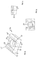
- FIGS. 3a to 3d The cutting insert according to the invention is shown in different views in FIGS. 3a to 3d.
- the cutting plate 14 has a total of four Cutting edges 10, 10 ', 10 ", 10"'.
- FIG. 3d which shows a side view of the rake face 30
- the edge separating the upper surface 11 from the rake surface 30 is made up of one middle section 9 and sections 10, 10 ′ raised relative to the middle section, which define the actual cutting edges.
- the middle section is essentially straight. Furthermore, the straight middle section 9 encloses on both sides also straight section 28 which, with the central section 9, has an angle ⁇ of approximately 140 ° includes.
- the raised sections 10, 10 ′ in turn, adjoin these sections 28 run essentially convexly curved, the curved region extending over an angular region ⁇ extends from about 110 °.
- 3e is therefore another Embodiment of the cutting insert shown, in which the convexly curved sections extend over a significantly larger angular range ⁇ , with straight sections 28 was waived.
- the exact design of the raised sections 10, 10 ', 28 is based on the first Line according to the desired puncture profile.
- the cutting insert in cross section on its two in the Figure visible cutting corners has two raised areas 10, 28 and 10 ', 28, which are clearly above the remaining upper surface 11 protrude, as is shown by the contour line 31.
- the Cutting insert is mirror-symmetrical with respect to the line of symmetry 32.
- the cutting insert 14 Approximately in the middle of the upper and lower surfaces, the cutting insert 14 has an attachment hole 29 on.
- the cutting insert 14 is provided in a tangential arrangement to be attached to a side milling cutter.
- the face 30 is the rake face while the parts of the upper surface 11 formed by the bead-like elevations represent the open spaces.
- Figure 3c shows a side view.
- the rake angles are Reduction of the cutting forces designed positive, but it goes without saying that a negative execution is possible.
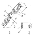
- a side milling cutter segment 15 is in a perspective and in a Sectional view shown.
- the cutting inserts according to the invention are 14 arranged inclined so that each inward elevation behind the contour of Diameter cutting 16 disappears. In this embodiment, therefore, only the outer ones come raised portions of the cutting insert 14 of the invention in contact with the workpiece.
- the axial inclination is about 7 ° here.
- Both the plunge cutting and the diameter cutting Chip chambers are assigned that serve to pick up chips and improve them Chip removal contribute.
- FIGS. 5a and 5b show an alternative embodiment of a side milling cutter segment 15 shown.
- This side milling cutter segment 15 has no diameter cutting edges 16, but only that Cutting inserts 14 according to the invention, which are used as plunge cutting and in Cross teeth are arranged.
- This side milling cutter is only used after using another disc cutter the diameter of the crank pin has been milled. It only serves the processing of the start-up collars, including the plunge-cut in the Transition area between the bearing pin or crank pin and crank arm.
- the milling cutter segments 15 shown are, as shown in FIG. 6, on the milling cutter disk 18 mounted.
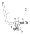
- This adjusting device is shown enlarged in FIG. 8 in a sectional view.
- the invention Cutting insert 14 is by means of a mounting screw 19 through the mounting hole of the cutting insert engages in a threaded bore of the side milling cutter segment 15, attached in the seat 26 of the side milling cutter segment 15.
- the mounting hole and the screw 19 and the corresponding threaded hole in the milling cutter segment are arranged such that the Insert is biased against the abutment surface 20 during assembly.
- the condition of the cutting insert by means of the adjusting device is at least still limited in the axial direction Movable direction.
- the stop surface 20 is part of the adjusting device 17, which consists of a differential screw consists of a wedge 22 with the stop surface 20 against the cutting insert 14 suppressed.
- the effective angle ⁇ of the wedge 22 is 6 ° in the embodiment shown.
- FIGS. 9a to 9f show two views of the differential screw 21.
- a torx profile is shown in FIG. 9a, with the help of which the differential screw 21 can be operated.
- Torx profile any other profile, such as B. a hexagon socket can be used.
- the Differential screw 21 has two right-handed threads 23 and 24.
- Another part of the The adjusting device 17 is the wedge 22 with the correspondingly inclined stop surface 20.
- the wedge 22 is shown in FIGS. 9c to 9f in different views in section and in perspective. He consists essentially of a threaded sleeve with outer wedge surfaces 20.
- the wedge 22 has a cylindrical projection 34 at its lower end.
- This approach works As can be clearly seen in FIG. 8, into a fitting bore 35, which is coaxial above the threaded bore of the side milling cutter segment is provided. Cylindrical extension 34 and fitting bore 35 are matched to one another in such a way that the cylindrical extension 34 in the fitting bore 35 is forced. This positive guidance ensures that the wedge on its stop surface 20 opposite side rests on a guide surface of the side milling cutter segment. Changing the insert is simplified because the wedge is also released always occupies a precisely defined position.
- the mode of operation of the adjusting device is shown in FIG. 10.
- the cutting insert 14 is fastened to the side milling cutter segment 15 with the aid of the fastening screw 19 in such a way that the fastening screw 19 presses the cutting insert 14 against the stop surface 20 of the part 22 and the cutting plate can be moved at least to a limited extent in the axial direction.
- the wedge 22 is pressed down, as a result of which the cutting insert 14 is pressed outwards.
- the limited mobility is achieved, for example, by the elastic properties of the fastening screw.
- the difference in pitch between the two threads 23, 24 of the differential screw 21 is 0.25 mm.
- the adjusting wedge 22 is displaced radially by 0.25 mm and the indexable insert is displaced axially by 0.025 mm.
- the indexable insert is axially adjusted by 0.001 mm. Consequently, fine adjustment is possible and the face tolerance is significantly reduced by the side milling cutter according to the invention.
- the runout tolerance could be set to less than 0.005 mm.
- the adjusting device 17 according to the invention also advantageously with others Cutting inserts and other side milling cutters can be used that do not have a raised section or have no inclined seat.
Landscapes
- Engineering & Computer Science (AREA)
- Mechanical Engineering (AREA)
- Milling Processes (AREA)
Applications Claiming Priority (2)
| Application Number | Priority Date | Filing Date | Title |
|---|---|---|---|
| DE10218630A DE10218630A1 (de) | 2002-04-25 | 2002-04-25 | Fräser mit Feineinstellung |
| DE10218630 | 2002-04-25 |
Publications (4)
| Publication Number | Publication Date |
|---|---|
| EP1356885A2 true EP1356885A2 (fr) | 2003-10-29 |
| EP1356885A3 EP1356885A3 (fr) | 2003-11-26 |
| EP1356885B1 EP1356885B1 (fr) | 2005-08-03 |
| EP1356885B8 EP1356885B8 (fr) | 2005-12-07 |
Family
ID=28685295
Family Applications (1)
| Application Number | Title | Priority Date | Filing Date |
|---|---|---|---|
| EP03008321A Expired - Lifetime EP1356885B8 (fr) | 2002-04-25 | 2003-04-10 | Fraise à disque et plaquette de coupe pour une fraise à disque |
Country Status (4)
| Country | Link |
|---|---|
| US (1) | US7101121B2 (fr) |
| EP (1) | EP1356885B8 (fr) |
| JP (1) | JP4662693B2 (fr) |
| DE (2) | DE10218630A1 (fr) |
Cited By (5)
| Publication number | Priority date | Publication date | Assignee | Title |
|---|---|---|---|---|
| WO2008012254A3 (fr) * | 2006-07-24 | 2008-05-08 | Walter Ag | Fraiseuse de vilebrequins |
| WO2010097082A1 (fr) * | 2009-02-24 | 2010-09-02 | Komet Group Gmbh | Outil mécanique comprenant un élément de type plaque réglable |
| WO2013144030A1 (fr) * | 2012-03-29 | 2013-10-03 | Walter Ag | Fraise à vilebrequins |
| US8690491B2 (en) | 2010-07-19 | 2014-04-08 | Ceratizit Austria Gesellschaft M.B.H. | Rotary cutting tool |
| EP2821170A1 (fr) | 2013-07-03 | 2015-01-07 | Sandvik Intellectual Property AB | Insert de coupe et outil de fraisage |
Families Citing this family (33)
| Publication number | Priority date | Publication date | Assignee | Title |
|---|---|---|---|---|
| DE10346790A1 (de) * | 2003-10-08 | 2005-05-04 | Kennametal Widia Gmbh & Co Kg | Schneideinsatz |
| US7544022B2 (en) * | 2004-02-16 | 2009-06-09 | Korloy Inc. | Milling cutter |
| DE202004015343U1 (de) * | 2004-07-06 | 2005-11-17 | Kennametal Inc. | Werkzeug und Vorrichtung zur Bearbeitung von Werkstücken |
| DE102005025815A1 (de) * | 2005-06-02 | 2006-12-07 | Kennametal Widia Produktions Gmbh & Co. Kg | Schneideinsatz, insbesondere zur Kurbelwellenbearbeitung |
| DE102005037310A1 (de) * | 2005-06-02 | 2006-12-07 | Kennametal Widia Produktions Gmbh & Co. Kg | Schneideinsatz |
| DE102005038021B4 (de) * | 2005-07-11 | 2016-07-21 | Kennametal Widia Produktions Gmbh & Co. Kg | Verfahren zur zerspanenden Bearbeitung von Kurbelwellen und Vorrichtung zur Durchführung dieses Verfahrens |
| DE202005012615U1 (de) * | 2005-08-08 | 2005-10-27 | Kennametal Widia Gmbh & Co. Kg | Schneideinsatz |
| SE529107C2 (sv) * | 2005-09-28 | 2007-05-02 | Seco Tools Ab | Fräs, fräskropp och vändskär där skäret har formen av en stympad pyramid |
| DE102005050210B4 (de) * | 2005-10-20 | 2010-11-11 | Kennametal Widia Produktions Gmbh & Co. Kg | Schneideinsatz und Fräser |
| DE102007013153B4 (de) * | 2007-03-20 | 2019-01-24 | Kennametal Inc. | Werkzeug |
| SE0702497L (sv) | 2007-11-14 | 2009-04-28 | Seco Tools Ab | Skärverktyg och skär för skärverktyg |
| IL187721A (en) * | 2007-11-28 | 2014-05-28 | Iscar Ltd | Cutting insert |
| ES2720358T3 (es) * | 2008-04-14 | 2019-07-19 | Taegu Tec Ltd | Inserto de corte intercambiable |
| JP5024189B2 (ja) * | 2008-06-04 | 2012-09-12 | 株式会社タンガロイ | チップの仮止め機構およびこれを備えたスローアウェイ式切削工具 |
| KR101017105B1 (ko) * | 2008-11-17 | 2011-02-25 | 대구텍 유한회사 | 인서트 및 이를 이용한 커터 |
| EP2465463A1 (fr) * | 2010-12-20 | 2012-06-20 | Jens Weyrauch | Procédé et dispositif de fabrication de prothèses dentaires extra-orales |
| DE102011003714B8 (de) * | 2011-02-07 | 2012-08-30 | Mag Ias Gmbh | Bearbeitungseinrichtung zum Bearbeiten von Kurbelwellen sowie Bearbeitungssystem mit einer derartigen Bearbeitungseinrichtung |
| AT12526U1 (de) * | 2011-03-09 | 2012-07-15 | Ceratizit Austria Gmbh | Schneideinsatz |
| CN103492110B (zh) * | 2011-04-26 | 2015-11-25 | 株式会社钨钛合金 | 切削刀片以及切削工具 |
| WO2012173255A1 (fr) * | 2011-06-17 | 2012-12-20 | 株式会社タンガロイ | Plaquette de coupe et outil de coupe rotatif |
| DE102011111513A1 (de) | 2011-08-31 | 2013-02-28 | Simtek Ag | Zerspanungswerkzeug |
| DE102012009097B4 (de) * | 2012-05-03 | 2023-11-02 | Kennametal Inc. | Fräswerkzeug zur Bearbeitung von gehärteten Kurbel- oder Nockenwellen |
| SE536590C2 (sv) * | 2012-07-05 | 2014-03-11 | Sandvik Intellectual Property | Frässkär med primär och sekundär släppningsyta samt periferisk, smal spånyta |
| US10160047B2 (en) | 2013-06-27 | 2018-12-25 | Kyocera Corporation | Cutting insert, cutting tool, and method for manufacturing a cut workpiece |
| USD741923S1 (en) * | 2013-12-27 | 2015-10-27 | Taegutec Ltd. | Cutting insert |
| DE102015102044B4 (de) * | 2015-02-12 | 2024-12-24 | Kennametal Inc. | Fräswerkzeug und Schneideinsatz |
| KR101780640B1 (ko) * | 2016-09-19 | 2017-09-21 | 한국야금 주식회사 | 고이송 편면형 절삭 인서트 및 이를 장착한 절삭 공구 |
| KR101941973B1 (ko) * | 2017-04-11 | 2019-01-24 | 한국야금 주식회사 | 고이송 절삭 인서트 및 이를 장착한 절삭 공구 |
| EP3456450B1 (fr) * | 2017-09-13 | 2022-12-21 | Sandvik Intellectual Property AB | Plaquette de coupe et outil de fraisage de vilebrequin |
| CN109434173A (zh) * | 2018-12-27 | 2019-03-08 | 安徽华菱汽车有限公司 | 一种铣刀及铣刀调节组件 |
| JP7067692B1 (ja) * | 2021-04-27 | 2022-05-16 | 住友電工ハードメタル株式会社 | 転削工具 |
| JP7012949B1 (ja) | 2021-07-15 | 2022-01-31 | 株式会社タンガロイ | 切削インサートおよび刃先交換式回転切削工具とそのボデー |
| US11433460B1 (en) | 2021-10-26 | 2022-09-06 | Prince Mohammad Bin Fahd University | Cutting insert |
Family Cites Families (27)
| Publication number | Priority date | Publication date | Assignee | Title |
|---|---|---|---|---|
| US2485280A (en) * | 1947-01-16 | 1949-10-18 | Worthington Pump & Mach Corp | Differential screw jack |
| US2955349A (en) * | 1958-03-13 | 1960-10-11 | Gen Electric | Cutting tool |
| US3195376A (en) * | 1963-03-01 | 1965-07-20 | Fansteel Metallurgical Corp | Boring head |
| US3792517A (en) * | 1971-08-17 | 1974-02-19 | Mc Crosky Tool Corp | Rotary machine cutting tools |
| US3708843A (en) * | 1971-11-05 | 1973-01-09 | Ingersoll Milling Machine Co | Holder for indexable cutting insert |
| DE2526345C2 (de) * | 1975-06-12 | 1983-06-09 | Fried. Krupp Gmbh, 4300 Essen | Scheibenfräser |
| FR2431897A1 (fr) * | 1978-07-25 | 1980-02-22 | Igman Sa | Plaquette rapportee pour outil de coupe rotatif |
| SE455676B (sv) * | 1984-11-12 | 1988-08-01 | Sandvik Ab | Korthalsborr, samt sker derfor |
| IL81283A (en) * | 1987-01-16 | 1990-11-05 | Kidan Cutting Tools | Cutting inserts and tools including same |
| US5037248A (en) * | 1987-05-13 | 1991-08-06 | Ingersoll Cm Systems Inc. | Cutter for monotonic cutting machine |
| FR2615769A1 (fr) * | 1987-06-01 | 1988-12-02 | Safety | Dispositif de reglage d'un outil de coupe |
| DE3939935A1 (de) * | 1989-12-02 | 1991-06-06 | Man Nutzfahrzeuge Ag | Verfahren zur herstellung einer kurbelwelle |
| SE470093B (sv) * | 1992-04-02 | 1993-11-08 | Sandvik Ab | Skär för skiv- eller planfräsar, samt fräsverktyg för sådana skär |
| SE501915C2 (sv) * | 1993-03-18 | 1995-06-19 | Sandvik Ab | Finfräs med urtag för axiellt inställbara kassetter |
| DE4403188A1 (de) * | 1994-02-02 | 1995-08-03 | Widia Heinlein Gmbh | Schlichtfräser |
| DE19630463A1 (de) * | 1996-07-27 | 1998-01-29 | Widia Gmbh | Expanderdorn |
| SE511567C2 (sv) * | 1997-04-18 | 1999-10-18 | Sandvik Ab | Skär för skivfräsar, samt skivfräs innefattande sådana skär |
| DE19739300A1 (de) * | 1997-09-08 | 1999-03-11 | Widia Gmbh | Schneideinsatz zum Schneiden von Profilen |
| DE19743971B4 (de) * | 1997-10-06 | 2008-06-19 | Widia Gmbh | Schneideinsatz, Fräswerkzeug und Verwendung des Fräswerkzeuges |
| US6056484A (en) * | 1998-08-07 | 2000-05-02 | Kennametal Inc. | Device and method for adjusting the position of cutting inserts mounted in a cutting tool |
| SE514029C2 (sv) * | 1998-10-27 | 2000-12-11 | Sandvik Ab | Verktyg för spånavskiljande bearbetning |
| SE512977C2 (sv) * | 1998-10-27 | 2000-06-12 | Sandvik Ab | Fräsverktyg |
| DE10006381A1 (de) * | 2000-02-12 | 2001-08-16 | Sandvik Ab | Schneideinsatz und zugehöriges Fräswerkzeug |
| DE10017645A1 (de) * | 2000-04-08 | 2001-10-11 | Sandvik Ab | Schneideinsatz für Nockenwellenfräser |
| DE10060283C1 (de) * | 2000-12-05 | 2002-06-27 | Mapal Fab Praezision | Werkzeug zur spanenden Feinbearbeitung eines Werkstücks |
| ES2213086T5 (es) * | 2000-12-05 | 2012-06-12 | MAPAL Fabrik für Präzisionswerkzeuge Dr. Kress KG | Herramienta para el mecanizado de precisión con arranque de virutas de piezas de trabajo |
| DE10144542C1 (de) * | 2001-09-10 | 2003-06-05 | Walter Ag | Schneidplatte und Fräswerkzeug |
-
2002
- 2002-04-25 DE DE10218630A patent/DE10218630A1/de not_active Ceased
-
2003
- 2003-04-10 DE DE50300888T patent/DE50300888D1/de not_active Expired - Lifetime
- 2003-04-10 EP EP03008321A patent/EP1356885B8/fr not_active Expired - Lifetime
- 2003-04-25 US US10/422,995 patent/US7101121B2/en not_active Expired - Fee Related
- 2003-04-25 JP JP2003122254A patent/JP4662693B2/ja not_active Expired - Fee Related
Cited By (8)
| Publication number | Priority date | Publication date | Assignee | Title |
|---|---|---|---|---|
| WO2008012254A3 (fr) * | 2006-07-24 | 2008-05-08 | Walter Ag | Fraiseuse de vilebrequins |
| WO2010097082A1 (fr) * | 2009-02-24 | 2010-09-02 | Komet Group Gmbh | Outil mécanique comprenant un élément de type plaque réglable |
| US8616808B2 (en) | 2009-02-24 | 2013-12-31 | Komet Group Gmbh | Machine tool having adjustable plate element |
| US8690491B2 (en) | 2010-07-19 | 2014-04-08 | Ceratizit Austria Gesellschaft M.B.H. | Rotary cutting tool |
| WO2013144030A1 (fr) * | 2012-03-29 | 2013-10-03 | Walter Ag | Fraise à vilebrequins |
| US9636759B2 (en) | 2012-03-29 | 2017-05-02 | Walter Ag | Crankshaft milling cutter |
| EP2821170A1 (fr) | 2013-07-03 | 2015-01-07 | Sandvik Intellectual Property AB | Insert de coupe et outil de fraisage |
| US9358621B2 (en) | 2013-07-03 | 2016-06-07 | Sandvik Intellectual Property Ab | Cutting insert and a milling tool |
Also Published As
| Publication number | Publication date |
|---|---|
| JP2004042254A (ja) | 2004-02-12 |
| EP1356885B8 (fr) | 2005-12-07 |
| EP1356885B1 (fr) | 2005-08-03 |
| EP1356885A3 (fr) | 2003-11-26 |
| US20030215294A1 (en) | 2003-11-20 |
| DE50300888D1 (de) | 2005-09-08 |
| DE10218630A1 (de) | 2003-11-06 |
| US7101121B2 (en) | 2006-09-05 |
| JP4662693B2 (ja) | 2011-03-30 |
Similar Documents
| Publication | Publication Date | Title |
|---|---|---|
| EP1356885B1 (fr) | Fraise à disque et plaquette de coupe pour une fraise à disque | |
| WO2013144030A1 (fr) | Fraise à vilebrequins | |
| EP0677350B1 (fr) | Plaquette de coupe, en particulier plaquette de coupe indexable | |
| EP0750960B1 (fr) | Foret, en particulier pour matériaux métalliques | |
| EP2049294A2 (fr) | Fraiseuse de vilebrequins | |
| EP1455980B1 (fr) | Outil de fraisage | |
| DE102017206144B3 (de) | Fräskopf für einen Kugelbahnfräser und Kugelbahnfräser mit einem solchen Fräskopf | |
| EP1864737A2 (fr) | Outil d'usinage par enlevement de copeaux | |
| WO2004078395A1 (fr) | Plaquette reversible servant a chanfreiner au moyen d'une tete de fraisage conique | |
| EP0566984B1 (fr) | Plaquette de coupe à fraiser | |
| EP2848342B1 (fr) | Outil de fraisage complet pour l'usinage rotatif de matériaux | |
| WO2007112734A1 (fr) | Insert de coupe et procédé d'usinage par enlèvement de copeaux de pièces entraînées en rotation | |
| EP1272305A1 (fr) | Plaquette de coupe de fraise pour arbres a cames | |
| WO2008052503A1 (fr) | Fraise dégrossisseuse et finisseuse | |
| DE102005038021B4 (de) | Verfahren zur zerspanenden Bearbeitung von Kurbelwellen und Vorrichtung zur Durchführung dieses Verfahrens | |
| DE10144542C1 (de) | Schneidplatte und Fräswerkzeug | |
| EP2342036B1 (fr) | Outil de brochage intérieur | |
| EP2451602A1 (fr) | Fraise en bout | |
| DE102017102473A1 (de) | Fräswerkzeug, insbesondere Tannenbaumfräser, und Herstellungsverfahren für ein Fräswerkzeug | |
| WO2007016890A1 (fr) | Plaquette de coupe | |
| WO1986004278A1 (fr) | Outil de brochage | |
| DE10333621B4 (de) | Schneideinsatz | |
| DE102008039135B4 (de) | Fräse für eine Kurbelwellen-Fräsvorrichtung und Fräseinsatz und Satz von Fräseinsätzen für einen Fräser für eine Kurbelwellen-Fräseinrichtung | |
| DE102005050210B4 (de) | Schneideinsatz und Fräser | |
| WO2009149812A1 (fr) | Fraisage rotatif avec stratégie d'attaque spéciale |
Legal Events
| Date | Code | Title | Description |
|---|---|---|---|
| PUAI | Public reference made under article 153(3) epc to a published international application that has entered the european phase |
Free format text: ORIGINAL CODE: 0009012 |
|
| PUAL | Search report despatched |
Free format text: ORIGINAL CODE: 0009013 |
|
| AK | Designated contracting states |
Kind code of ref document: A2 Designated state(s): AT BE BG CH CY CZ DE DK EE ES FI FR GB GR HU IE IT LI LU MC NL PT RO SE SI SK TR |
|
| AX | Request for extension of the european patent |
Extension state: AL LT LV MK |
|
| AK | Designated contracting states |
Kind code of ref document: A3 Designated state(s): AT BE BG CH CY CZ DE DK EE ES FI FR GB GR HU IE IT LI LU MC NL PT RO SE SI SK TR |
|
| AX | Request for extension of the european patent |
Extension state: AL LT LV MK |
|
| 17P | Request for examination filed |
Effective date: 20040401 |
|
| AKX | Designation fees paid |
Designated state(s): DE FR GB IT |
|
| 17Q | First examination report despatched |
Effective date: 20040804 |
|
| GRAP | Despatch of communication of intention to grant a patent |
Free format text: ORIGINAL CODE: EPIDOSNIGR1 |
|
| GRAS | Grant fee paid |
Free format text: ORIGINAL CODE: EPIDOSNIGR3 |
|
| GRAA | (expected) grant |
Free format text: ORIGINAL CODE: 0009210 |
|
| RAP1 | Party data changed (applicant data changed or rights of an application transferred) |
Owner name: SANDVIK INTELLECTUAL PROPERTY HB |
|
| AK | Designated contracting states |
Kind code of ref document: B1 Designated state(s): DE FR GB IT |
|
| REG | Reference to a national code |
Ref country code: GB Ref legal event code: FG4D Free format text: NOT ENGLISH |
|
| RAP2 | Party data changed (patent owner data changed or rights of a patent transferred) |
Owner name: SANDVIK INTELLECTUAL PROPERTY AB |
|
| REF | Corresponds to: |
Ref document number: 50300888 Country of ref document: DE Date of ref document: 20050908 Kind code of ref document: P |
|
| GBT | Gb: translation of ep patent filed (gb section 77(6)(a)/1977) |
Effective date: 20050830 |
|
| ET | Fr: translation filed | ||
| PLBE | No opposition filed within time limit |
Free format text: ORIGINAL CODE: 0009261 |
|
| STAA | Information on the status of an ep patent application or granted ep patent |
Free format text: STATUS: NO OPPOSITION FILED WITHIN TIME LIMIT |
|
| 26N | No opposition filed |
Effective date: 20060504 |
|
| PGFP | Annual fee paid to national office [announced via postgrant information from national office to epo] |
Ref country code: DE Payment date: 20120425 Year of fee payment: 10 |
|
| PG25 | Lapsed in a contracting state [announced via postgrant information from national office to epo] |
Ref country code: DE Free format text: LAPSE BECAUSE OF NON-PAYMENT OF DUE FEES Effective date: 20131101 |
|
| REG | Reference to a national code |
Ref country code: DE Ref legal event code: R119 Ref document number: 50300888 Country of ref document: DE Effective date: 20131101 |
|
| REG | Reference to a national code |
Ref country code: FR Ref legal event code: PLFP Year of fee payment: 14 |
|
| REG | Reference to a national code |
Ref country code: FR Ref legal event code: PLFP Year of fee payment: 15 |
|
| PGFP | Annual fee paid to national office [announced via postgrant information from national office to epo] |
Ref country code: FR Payment date: 20170313 Year of fee payment: 15 |
|
| PGFP | Annual fee paid to national office [announced via postgrant information from national office to epo] |
Ref country code: GB Payment date: 20170405 Year of fee payment: 15 |
|
| PGFP | Annual fee paid to national office [announced via postgrant information from national office to epo] |
Ref country code: IT Payment date: 20170420 Year of fee payment: 15 |
|
| GBPC | Gb: european patent ceased through non-payment of renewal fee |
Effective date: 20180410 |
|
| PG25 | Lapsed in a contracting state [announced via postgrant information from national office to epo] |
Ref country code: GB Free format text: LAPSE BECAUSE OF NON-PAYMENT OF DUE FEES Effective date: 20180410 |
|
| PG25 | Lapsed in a contracting state [announced via postgrant information from national office to epo] |
Ref country code: IT Free format text: LAPSE BECAUSE OF NON-PAYMENT OF DUE FEES Effective date: 20180410 Ref country code: FR Free format text: LAPSE BECAUSE OF NON-PAYMENT OF DUE FEES Effective date: 20180430 |