EP1357009A2 - Système de freinage avec timonerie de frein pour véhicules ferroviaires - Google Patents
Système de freinage avec timonerie de frein pour véhicules ferroviaires Download PDFInfo
- Publication number
- EP1357009A2 EP1357009A2 EP03007588A EP03007588A EP1357009A2 EP 1357009 A2 EP1357009 A2 EP 1357009A2 EP 03007588 A EP03007588 A EP 03007588A EP 03007588 A EP03007588 A EP 03007588A EP 1357009 A2 EP1357009 A2 EP 1357009A2
- Authority
- EP
- European Patent Office
- Prior art keywords
- bearing
- brake
- braking device
- elastic
- ring
- Prior art date
- Legal status (The legal status is an assumption and is not a legal conclusion. Google has not performed a legal analysis and makes no representation as to the accuracy of the status listed.)
- Granted
Links
- 239000011324 bead Substances 0.000 claims description 3
- 230000035939 shock Effects 0.000 description 5
- 238000013016 damping Methods 0.000 description 4
- 238000010276 construction Methods 0.000 description 3
- XEEYBQQBJWHFJM-UHFFFAOYSA-N Iron Chemical compound [Fe] XEEYBQQBJWHFJM-UHFFFAOYSA-N 0.000 description 2
- 238000005457 optimization Methods 0.000 description 2
- 238000010521 absorption reaction Methods 0.000 description 1
- 230000015572 biosynthetic process Effects 0.000 description 1
- 230000005489 elastic deformation Effects 0.000 description 1
- 230000003993 interaction Effects 0.000 description 1
- 229910052742 iron Inorganic materials 0.000 description 1
- 238000000034 method Methods 0.000 description 1
- 239000000725 suspension Substances 0.000 description 1
Images

Classifications
-
- F—MECHANICAL ENGINEERING; LIGHTING; HEATING; WEAPONS; BLASTING
- F16—ENGINEERING ELEMENTS AND UNITS; GENERAL MEASURES FOR PRODUCING AND MAINTAINING EFFECTIVE FUNCTIONING OF MACHINES OR INSTALLATIONS; THERMAL INSULATION IN GENERAL
- F16F—SPRINGS; SHOCK-ABSORBERS; MEANS FOR DAMPING VIBRATION
- F16F1/00—Springs
- F16F1/36—Springs made of rubber or other material having high internal friction, e.g. thermoplastic elastomers
- F16F1/38—Springs made of rubber or other material having high internal friction, e.g. thermoplastic elastomers with a sleeve of elastic material between a rigid outer sleeve and a rigid inner sleeve or pin, i.e. bushing-type
-
- B—PERFORMING OPERATIONS; TRANSPORTING
- B60—VEHICLES IN GENERAL
- B60T—VEHICLE BRAKE CONTROL SYSTEMS OR PARTS THEREOF; BRAKE CONTROL SYSTEMS OR PARTS THEREOF, IN GENERAL; ARRANGEMENT OF BRAKING ELEMENTS ON VEHICLES IN GENERAL; PORTABLE DEVICES FOR PREVENTING UNWANTED MOVEMENT OF VEHICLES; VEHICLE MODIFICATIONS TO FACILITATE COOLING OF BRAKES
- B60T17/00—Component parts, details, or accessories of power brake systems not covered by groups B60T8/00, B60T13/00 or B60T15/00, or presenting other characteristic features
- B60T17/08—Brake cylinders other than ultimate actuators
- B60T17/088—Mounting arrangements
-
- B—PERFORMING OPERATIONS; TRANSPORTING
- B61—RAILWAYS
- B61H—BRAKES OR OTHER RETARDING DEVICES SPECIALLY ADAPTED FOR RAIL VEHICLES; ARRANGEMENT OR DISPOSITION THEREOF IN RAIL VEHICLES
- B61H5/00—Applications or arrangements of brakes with substantially radial braking surfaces pressed together in axial direction, e.g. disc brakes
-
- F—MECHANICAL ENGINEERING; LIGHTING; HEATING; WEAPONS; BLASTING
- F16—ENGINEERING ELEMENTS AND UNITS; GENERAL MEASURES FOR PRODUCING AND MAINTAINING EFFECTIVE FUNCTIONING OF MACHINES OR INSTALLATIONS; THERMAL INSULATION IN GENERAL
- F16D—COUPLINGS FOR TRANSMITTING ROTATION; CLUTCHES; BRAKES
- F16D55/00—Brakes with substantially-radial braking surfaces pressed together in axial direction, e.g. disc brakes
- F16D55/02—Brakes with substantially-radial braking surfaces pressed together in axial direction, e.g. disc brakes with axially-movable discs or pads pressed against axially-located rotating members
- F16D55/22—Brakes with substantially-radial braking surfaces pressed together in axial direction, e.g. disc brakes with axially-movable discs or pads pressed against axially-located rotating members by clamping an axially-located rotating disc between movable braking members, e.g. movable brake discs or brake pads
- F16D55/224—Brakes with substantially-radial braking surfaces pressed together in axial direction, e.g. disc brakes with axially-movable discs or pads pressed against axially-located rotating members by clamping an axially-located rotating disc between movable braking members, e.g. movable brake discs or brake pads with a common actuating member for the braking members
- F16D55/2245—Brakes with substantially-radial braking surfaces pressed together in axial direction, e.g. disc brakes with axially-movable discs or pads pressed against axially-located rotating members by clamping an axially-located rotating disc between movable braking members, e.g. movable brake discs or brake pads with a common actuating member for the braking members in which the common actuating member acts on two levers carrying the braking members, e.g. tong-type brakes
Definitions
- the invention relates to a braking device, in particular for rail vehicles with a brake linkage, the at least one first brake partner carries, which can be brought into operative contact with a second brake partner, wherein the brake linkage via at least one elastic bearing with a fixed point connected is.
- Braking devices of the generic type are known. These are for example designed as disc brakes.
- Such disc brakes include pliers arranged brake levers that rotate on one Brake cable are articulated.
- a drive device By means of a drive device are the Brake lever pivotable about an axis of rotation, so that on the brake levers arranged brake pads as the first brake in operative contact with a second brake partner, for example in rail vehicles, with a arranged on an axle brake disc can be brought.
- the drive means for such disc brakes formed by compressed air cylinder.
- the braking device To derive the braking force, the braking device with a fixed point at Rail vehicles a bogie, connected. It is known that To connect the brake bridge to the bogie via an elastic bearing.
- the Brake bridge is in this case connected non-positively with a bearing bush, the is penetrated by a bearing pin, in turn, with the bogie positively connected.
- the bearing for mounting the braking device on the bogie as elastic To train camp.
- the bearing bolt connected to the bogie via an elastic means, usually a rubber insert or the like, connected to the bearing bush.
- This elastic bearing serves a vibration damping.
- the invention is based on the object, a braking device of the generic type To create a kind that is characterized by a robust, functional and a characterized by low space-consuming structure.
- this object is achieved by a braking device with the in the Claim 1 mentioned features.
- the elastic bearing is formed in two stages, is advantageous achieved that an optimization of the warehouse both on a normal operation as can also be done on a load operation.
- the bearing comprises a first elastic stage and a second inelastic stage, can be the vibrations occurring during normal operation, To damp shocks or the like through the elastic stage of the bearing while in a load operation large forces occurring by the second High rigidity level of the bearing can be safely derived.
- the elastic level of the bearing can be reduced to a necessary minimum, so that the taken from the elastic stage of the camp Construction is also reduced to the necessary minimum.
- the elastic Stage therefore no longer needs for the absorption of forces in load operation to be interpreted. This results in significant advantages in the Functionality of the entire warehouse as well as in particular during an optimization of its construction volume.
- the elastic bearing a non-positively connected to the brake rod bushing and a non-positively connected to the fixed point bearing pin comprising, wherein the elastic step formed by an elastic means is, via which the bearing pin is connected to the bearing bush.
- the bearing bolt encompassing elastic means - on the bearing pin with the bearing bush communicates with - during the normal operation of the braking device expected loads (blows, vibrations or the like) to adjust.
- a thickness of the elastic means to a necessary Minimum be reduced. This reduces the total Construction volume requirement of the warehouse.
- the Bearing one, the bearing pin coaxially embracing and spaced too this arranged support ring, preferably a bearing ring of the Assigned bearing pin.
- Support ring of the bearing bush and bearing ring of the bearing bolt are spaced by the elastic means of the elastic bearing stage held each other. This ensures that the through the support ring and the bearing ring formed second stage high rigidity of the bearing inactive is and only when a minimum force is exceeded by the first elastic Level of the camp is predetermined, acts. This minimum force is through a Thickness and / or a modulus of elasticity of the first elastic stage adjustable.
- the Form support ring and the bearing ring corresponding bearing surfaces wherein Preferably, the support ring a concave bearing surface and the bearing ring a has convex bearing surface.
- the support ring a concave bearing surface and the bearing ring a has convex bearing surface.
- FIG. 1 shows a braking device designated as a whole by 10 in one embodiment schematic perspective view.
- the braking device 10 is as a disc brake trained and used, for example, the braking of rail vehicles.
- the braking device 10 comprises a brake linkage 12, which is a brake lever 14 and a brake bridge 16 includes.
- the brake lever 14 is about a rotation axis 18 rotatably hinged to the brake bridge 16.
- the brake lever 14 is on the one hand with a drive device 20, in the example shown with a Compressed air cylinder, connected.
- a Brake pad 22 At the drive device 20 facing away from Side - with respect to the axis of rotation 18 - carries the brake lever 14 a Brake pad 22, which serves as a brake partner.
- another brake pad 22 is disposed on a brake pad holder 24 is attached.
- the brake pads 22 form a first brake partner with a - not shown - - cooperate second brake partner.
- Of the second brake partner is for example arranged on a wheel axle Brake disc which engages in the space between the brake pads 22.
- the braking device 10 is via suspension lugs 26 (also referred to as hanging iron) on a bogie, not shown, of a rail vehicle attached.
- the braking device 10 is also a bearing 28 with the bogie connected.
- a bearing bush 30 frictionally with the brake bridge 16 connected while a bearing pin 32 frictionally with the Bogie is connected.
- the bearing 28 is - as will be explained later - as formed elastic bearing.
- a brake caliper shape is provided, which has no hanging pockets. The forces that occur are then taken over a second rubber bearing.
- the general structure and operation of the braking device 10 are known, so that in the context of the present description thereto not closer will be received.
- the drive device 20 with compressed air acted upon, so that a piston of the drive device 20, an actuating force on the brake lever 14 exerts.
- This is then on the axis of rotation 18th pivoted so that the brake pads 22 are moved towards each other. hereby Pinching the between the brake pads 22 are located Brake disc, causing it to frictional contact between the brake partners comes and the braking process is initiated.
- the braking device 10 During the intended use of the braking device 10 subject this a considerable mechanical stress. In particular, be Blows, vibrations or the like during the driving of the Rail vehicle via the bogie to the braking device 10 transmitted. To achieve a damping of these shocks and vibrations, the Braking device 10 connected via the elastic bearing 28 to the bogie. The elastic bearing 28 thus serves to decouple the braking device 10 from the blows, vibrations or the like.
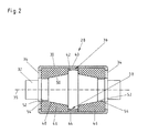
- FIG. 2 shows a schematic sectional view of the elastic bearing 28. It is clear that the bearing bushing of the bearing pin 32 axially penetrated becomes.
- the bushing has for this purpose through holes 34, whose Diameter larger than a diameter of the bearing pin in the area of Through holes 34.
- Bearing bushing 30 and bearing pin 32 are preferably formed rotationally symmetrical to a longitudinal axis 35.
- the bearing bush 30 has an inner support ring 36, the bearing pin 32 coaxial embraces.
- the support ring 36 is associated with a bearing ring 38 of the bearing pin 32.
- the support ring 36 has a concave first bearing surface 40 which is a convex second bearing surface 42 of the bearing ring 38 is assigned in the idle state Support ring 36 and bearing ring 38 are spaced from each other. Between Support ring 36 and bearing ring 38 is an annular gap 44, for example is designed as an air gap.
- the bearing pin 32 is within the bearing bush 30 by elastic means 46 held.
- the elastic means 46 are for example as rubber rings or formed like.
- the elastic means 46 each have an axial Through opening 48 whose inner contour of an outer contour 50 of the bearing pin 32 is adjusted.
- the bearing pin 32 has two annular grooves 52, in which the elastic means 46 each engage with an annular bead 54.
- annular grooves 52 and annular beads 54 By the interaction of annular grooves 52 and annular beads 54 is a Precise positioning of the bearing pin 32 within the bearing bush 30 possible. There is virtually a self-aligning positioning of the bearing pin 32. In particular, this results in an alignment of the bearing ring 38 to the Support ring 36, so that the associated bearing surfaces 40 and 42 coaxial with each other.
- the bearing bush 30 is - as Figure 1 illustrates - with the brake bridge sixteenth positively connected, while the bearing pin 32 with the not shown Bogie is positively connected. Acting on the bogie Shocks, vibrations or the like are from the bearing pin 32nd taken and transmitted via the elastic means to the bearing bush 30. By the elastic means 46 in this case takes place a decoupling, so that a vibration damping is given. The amount of vibration damping can by a thickness of the elastic means 46 and / or a modulus of elasticity the elastic means 46 are adjusted.
- the design found a two-stage elastic Bearing 28 is realized.
- a first elastic step is made by the elastic Means 46 realized while a second stage with high rigidity through the bearing ring 38 is realized in connection with the support ring 36.
- the elastic stage may be chosen during the a normal stress occurring vibrations, shocks or the like be set while bearing load 38 at a load stress and support ring 36 absorb the forces.
- the concave bearing surface 40 and on the other hand the convex bearing surface 42, is In addition, it ensures that a gimbal movement of the bearing pin 32 is maintained in the load case.
- the bearing surfaces 40 and 42 can Here - without causing a reduction in the power dissipating bearing surface comes - to be moved relative to each other.
Landscapes
- Engineering & Computer Science (AREA)
- General Engineering & Computer Science (AREA)
- Mechanical Engineering (AREA)
- Transportation (AREA)
- Braking Arrangements (AREA)
- Vibration Prevention Devices (AREA)
Applications Claiming Priority (2)
| Application Number | Priority Date | Filing Date | Title |
|---|---|---|---|
| DE20206648U | 2002-04-25 | ||
| DE20206648U DE20206648U1 (de) | 2002-04-25 | 2002-04-25 | Bremseinrichtung, insbesondere für Schienenfahrzeuge |
Publications (3)
| Publication Number | Publication Date |
|---|---|
| EP1357009A2 true EP1357009A2 (fr) | 2003-10-29 |
| EP1357009A3 EP1357009A3 (fr) | 2005-05-04 |
| EP1357009B1 EP1357009B1 (fr) | 2007-02-21 |
Family
ID=7970573
Family Applications (1)
| Application Number | Title | Priority Date | Filing Date |
|---|---|---|---|
| EP03007588A Expired - Lifetime EP1357009B1 (fr) | 2002-04-25 | 2003-04-02 | Système de freinage avec timonerie de frein pour véhicules ferroviaires |
Country Status (5)
| Country | Link |
|---|---|
| EP (1) | EP1357009B1 (fr) |
| AT (1) | ATE354509T1 (fr) |
| DE (2) | DE20206648U1 (fr) |
| DK (1) | DK1357009T3 (fr) |
| ES (1) | ES2283672T3 (fr) |
Cited By (2)
| Publication number | Priority date | Publication date | Assignee | Title |
|---|---|---|---|---|
| US8006812B2 (en) | 2006-04-07 | 2011-08-30 | Faiveley Transport Nordic Ab | Disc brake caliper |
| DE102013213618A1 (de) * | 2013-07-11 | 2015-01-15 | Siemens Aktiengesellschaft | Bremsvorrichtung |
Families Citing this family (1)
| Publication number | Priority date | Publication date | Assignee | Title |
|---|---|---|---|---|
| DE102006007160A1 (de) * | 2006-02-16 | 2007-08-30 | Jörn GmbH | Gelenklager, insbesondere für ein Fahrwerk eines Nutzfahrzeugs |
Family Cites Families (4)
| Publication number | Priority date | Publication date | Assignee | Title |
|---|---|---|---|---|
| DE2504804A1 (de) * | 1975-02-05 | 1976-08-19 | Knorr Bremse Gmbh | Scheibenbremse fuer schienenfahrzeuge |
| JPS5539866Y2 (fr) * | 1975-03-19 | 1980-09-18 | ||
| JPS62132043A (ja) * | 1985-12-05 | 1987-06-15 | Akebono Brake Ind Co Ltd | キヤリパ支持構造 |
| EP0482282B1 (fr) * | 1990-10-22 | 1994-01-26 | Metzeler Gimetall Ag | Support de manchette axial |
-
2002
- 2002-04-25 DE DE20206648U patent/DE20206648U1/de not_active Expired - Lifetime
-
2003
- 2003-04-02 DE DE50306556T patent/DE50306556D1/de not_active Expired - Lifetime
- 2003-04-02 AT AT03007588T patent/ATE354509T1/de active
- 2003-04-02 DK DK03007588T patent/DK1357009T3/da active
- 2003-04-02 ES ES03007588T patent/ES2283672T3/es not_active Expired - Lifetime
- 2003-04-02 EP EP03007588A patent/EP1357009B1/fr not_active Expired - Lifetime
Cited By (2)
| Publication number | Priority date | Publication date | Assignee | Title |
|---|---|---|---|---|
| US8006812B2 (en) | 2006-04-07 | 2011-08-30 | Faiveley Transport Nordic Ab | Disc brake caliper |
| DE102013213618A1 (de) * | 2013-07-11 | 2015-01-15 | Siemens Aktiengesellschaft | Bremsvorrichtung |
Also Published As
| Publication number | Publication date |
|---|---|
| DE50306556D1 (de) | 2007-04-05 |
| ES2283672T3 (es) | 2007-11-01 |
| ATE354509T1 (de) | 2007-03-15 |
| DE20206648U1 (de) | 2002-08-08 |
| DK1357009T3 (da) | 2007-06-25 |
| EP1357009B1 (fr) | 2007-02-21 |
| EP1357009A3 (fr) | 2005-05-04 |
Similar Documents
| Publication | Publication Date | Title |
|---|---|---|
| DE3217959C2 (de) | Vorrichtung zur vibrationsisolierten Befestigung eines Fahrschemels oder Aggregathalters | |
| EP1499510B1 (fr) | Triangle de suspension | |
| DE60117999T2 (de) | Lenkachsanordnung | |
| DE69621102T2 (de) | Verschachtelte Dämpfungsvorrichtung mit relativer Bewegung | |
| DE3800537A1 (de) | Scheibenbremsenanordnung | |
| DE3340442C2 (de) | Fahrwerks-Baugruppe für die Anbringung von Radachsen und Bremsen bei Kraftfahrzeugen | |
| DE102021106830B3 (de) | Riemenscheibenentkoppler mit Schaufelgeometrie zum Einleiten eines Kühlfluids | |
| EP2300729A1 (fr) | Système de freinage pour freins à disque | |
| DE2811034A1 (de) | Befestigungsauge, insbesondere fuer stossdaempfer | |
| DE3508039C2 (de) | Innen umgriffene Scheibenbremse, insbesondere für Kraftfahrzeuge | |
| DE102012108689A1 (de) | Scheibenbremse für ein Fahrzeug | |
| DE3939192C2 (de) | Gelenkverbindung zwischen dem kippzylinder und dem kippbaren fahrerhaus eines lastkraftwagens | |
| DE102009007330A1 (de) | Fahrzeugscheibenbremse | |
| DE69621565T2 (de) | Bremsgestänge, dass einen Coulomb-Dämpfer zur Biegung enthält | |
| DE102009039841A1 (de) | Feder-Dämpfer-Element für eine Fahrerhauslagerung | |
| EP3153737B1 (fr) | Palier de châssis | |
| DE102005001742A1 (de) | Federbein mit verstellbarem Federteller | |
| EP1357009A2 (fr) | Système de freinage avec timonerie de frein pour véhicules ferroviaires | |
| DE102004006626A1 (de) | Integrierter Radlageraufbau für eine Radaufhängung eines Kraftfahrzeugs | |
| EP2290256B1 (fr) | Frein à étrier pour un véhicule sur rails doté d'une suspension d'étrier de freinage élastique | |
| EP0121601B1 (fr) | Structure de leviers de frein pour un frein à disque | |
| DE102013103064A1 (de) | Nachstelleinrichtung für eine Scheibenbremse und eine entsprechende Scheibenbremse | |
| EP1820674B1 (fr) | Jambe de suspension réglable pour véhicules | |
| DE19611427A1 (de) | Lenkbare Achsanordnung | |
| WO2020038854A1 (fr) | Essieu d'un véhicule |
Legal Events
| Date | Code | Title | Description |
|---|---|---|---|
| PUAI | Public reference made under article 153(3) epc to a published international application that has entered the european phase |
Free format text: ORIGINAL CODE: 0009012 |
|
| AK | Designated contracting states |
Kind code of ref document: A2 Designated state(s): AT BE BG CH CY CZ DE DK EE ES FI FR GB GR HU IE IT LI LU MC NL PT RO SE SI SK TR |
|
| AX | Request for extension of the european patent |
Extension state: AL LT LV MK |
|
| RIN1 | Information on inventor provided before grant (corrected) |
Inventor name: MERKEL, THOMAS, DR. Inventor name: PLITZKO, CLAUDIUS |
|
| PUAL | Search report despatched |
Free format text: ORIGINAL CODE: 0009013 |
|
| AK | Designated contracting states |
Kind code of ref document: A3 Designated state(s): AT BE BG CH CY CZ DE DK EE ES FI FR GB GR HU IE IT LI LU MC NL PT RO SE SI SK TR |
|
| AX | Request for extension of the european patent |
Extension state: AL LT LV MK |
|
| RAP1 | Party data changed (applicant data changed or rights of an application transferred) |
Owner name: FAIVELEY TRANSPORT REMSCHEID GMBH |
|
| 17P | Request for examination filed |
Effective date: 20050727 |
|
| AKX | Designation fees paid |
Designated state(s): AT BE BG CH CY CZ DE DK EE ES FI FR GB GR HU IE IT LI LU MC NL PT RO SE SI SK TR |
|
| GRAP | Despatch of communication of intention to grant a patent |
Free format text: ORIGINAL CODE: EPIDOSNIGR1 |
|
| GRAS | Grant fee paid |
Free format text: ORIGINAL CODE: EPIDOSNIGR3 |
|
| GRAA | (expected) grant |
Free format text: ORIGINAL CODE: 0009210 |
|
| AK | Designated contracting states |
Kind code of ref document: B1 Designated state(s): AT BE BG CH CY CZ DE DK EE ES FI FR GB GR HU IE IT LI LU MC NL PT RO SE SI SK TR |
|
| PG25 | Lapsed in a contracting state [announced via postgrant information from national office to epo] |
Ref country code: IE Free format text: LAPSE BECAUSE OF FAILURE TO SUBMIT A TRANSLATION OF THE DESCRIPTION OR TO PAY THE FEE WITHIN THE PRESCRIBED TIME-LIMIT Effective date: 20070221 Ref country code: FI Free format text: LAPSE BECAUSE OF FAILURE TO SUBMIT A TRANSLATION OF THE DESCRIPTION OR TO PAY THE FEE WITHIN THE PRESCRIBED TIME-LIMIT Effective date: 20070221 Ref country code: SI Free format text: LAPSE BECAUSE OF FAILURE TO SUBMIT A TRANSLATION OF THE DESCRIPTION OR TO PAY THE FEE WITHIN THE PRESCRIBED TIME-LIMIT Effective date: 20070221 |
|
| REG | Reference to a national code |
Ref country code: GB Ref legal event code: FG4D Free format text: NOT ENGLISH |
|
| REG | Reference to a national code |
Ref country code: CH Ref legal event code: EP |
|
| GBT | Gb: translation of ep patent filed (gb section 77(6)(a)/1977) |
Effective date: 20070307 |
|
| REF | Corresponds to: |
Ref document number: 50306556 Country of ref document: DE Date of ref document: 20070405 Kind code of ref document: P |
|
| REG | Reference to a national code |
Ref country code: IE Ref legal event code: FG4D Free format text: LANGUAGE OF EP DOCUMENT: GERMAN |
|
| RAP2 | Party data changed (patent owner data changed or rights of a patent transferred) |
Owner name: FAIVELEY TRANSPORT REMSCHEID GMBH |
|
| PG25 | Lapsed in a contracting state [announced via postgrant information from national office to epo] |
Ref country code: BG Free format text: LAPSE BECAUSE OF EXPIRATION OF PROTECTION Effective date: 20070522 |
|
| REG | Reference to a national code |
Ref country code: SE Ref legal event code: TRGR |
|
| REG | Reference to a national code |
Ref country code: DK Ref legal event code: T3 |
|
| NLT2 | Nl: modifications (of names), taken from the european patent patent bulletin |
Owner name: FAIVELEY TRANSPORT REMSCHEID GMBH Effective date: 20070502 |
|
| PG25 | Lapsed in a contracting state [announced via postgrant information from national office to epo] |
Ref country code: PT Free format text: LAPSE BECAUSE OF FAILURE TO SUBMIT A TRANSLATION OF THE DESCRIPTION OR TO PAY THE FEE WITHIN THE PRESCRIBED TIME-LIMIT Effective date: 20070723 |
|
| REG | Reference to a national code |
Ref country code: HU Ref legal event code: AG4A Ref document number: E001787 Country of ref document: HU |
|
| ET | Fr: translation filed | ||
| REG | Reference to a national code |
Ref country code: IE Ref legal event code: FD4D |
|
| REG | Reference to a national code |
Ref country code: ES Ref legal event code: FG2A Ref document number: 2283672 Country of ref document: ES Kind code of ref document: T3 |
|
| PG25 | Lapsed in a contracting state [announced via postgrant information from national office to epo] |
Ref country code: SK Free format text: LAPSE BECAUSE OF FAILURE TO SUBMIT A TRANSLATION OF THE DESCRIPTION OR TO PAY THE FEE WITHIN THE PRESCRIBED TIME-LIMIT Effective date: 20070221 |
|
| REG | Reference to a national code |
Ref country code: CH Ref legal event code: PL |
|
| PLBE | No opposition filed within time limit |
Free format text: ORIGINAL CODE: 0009261 |
|
| STAA | Information on the status of an ep patent application or granted ep patent |
Free format text: STATUS: NO OPPOSITION FILED WITHIN TIME LIMIT |
|
| BECA | Be: change of holder's address |
Owner name: *FAIVELEY TRANSPORT REMSCHEID G.M.B.H. Effective date: 20070221 Owner name: PAPENBERGER STRASSE 38, D-42859 REMSCHEID Effective date: 20070221 |
|
| PG25 | Lapsed in a contracting state [announced via postgrant information from national office to epo] |
Ref country code: RO Free format text: LAPSE BECAUSE OF FAILURE TO SUBMIT A TRANSLATION OF THE DESCRIPTION OR TO PAY THE FEE WITHIN THE PRESCRIBED TIME-LIMIT Effective date: 20070221 Ref country code: CZ Free format text: LAPSE BECAUSE OF FAILURE TO SUBMIT A TRANSLATION OF THE DESCRIPTION OR TO PAY THE FEE WITHIN THE PRESCRIBED TIME-LIMIT Effective date: 20070221 |
|
| 26N | No opposition filed |
Effective date: 20071122 |
|
| PG25 | Lapsed in a contracting state [announced via postgrant information from national office to epo] |
Ref country code: CH Free format text: LAPSE BECAUSE OF NON-PAYMENT OF DUE FEES Effective date: 20070430 Ref country code: LI Free format text: LAPSE BECAUSE OF NON-PAYMENT OF DUE FEES Effective date: 20070430 |
|
| PG25 | Lapsed in a contracting state [announced via postgrant information from national office to epo] |
Ref country code: GR Free format text: LAPSE BECAUSE OF FAILURE TO SUBMIT A TRANSLATION OF THE DESCRIPTION OR TO PAY THE FEE WITHIN THE PRESCRIBED TIME-LIMIT Effective date: 20070522 |
|
| PG25 | Lapsed in a contracting state [announced via postgrant information from national office to epo] |
Ref country code: EE Free format text: LAPSE BECAUSE OF FAILURE TO SUBMIT A TRANSLATION OF THE DESCRIPTION OR TO PAY THE FEE WITHIN THE PRESCRIBED TIME-LIMIT Effective date: 20070221 |
|
| PG25 | Lapsed in a contracting state [announced via postgrant information from national office to epo] |
Ref country code: MC Free format text: LAPSE BECAUSE OF NON-PAYMENT OF DUE FEES Effective date: 20070430 |
|
| PG25 | Lapsed in a contracting state [announced via postgrant information from national office to epo] |
Ref country code: CY Free format text: LAPSE BECAUSE OF FAILURE TO SUBMIT A TRANSLATION OF THE DESCRIPTION OR TO PAY THE FEE WITHIN THE PRESCRIBED TIME-LIMIT Effective date: 20070221 |
|
| PG25 | Lapsed in a contracting state [announced via postgrant information from national office to epo] |
Ref country code: LU Free format text: LAPSE BECAUSE OF NON-PAYMENT OF DUE FEES Effective date: 20070402 |
|
| PG25 | Lapsed in a contracting state [announced via postgrant information from national office to epo] |
Ref country code: TR Free format text: LAPSE BECAUSE OF FAILURE TO SUBMIT A TRANSLATION OF THE DESCRIPTION OR TO PAY THE FEE WITHIN THE PRESCRIBED TIME-LIMIT Effective date: 20070221 |
|
| REG | Reference to a national code |
Ref country code: FR Ref legal event code: PLFP Year of fee payment: 14 |
|
| REG | Reference to a national code |
Ref country code: FR Ref legal event code: PLFP Year of fee payment: 15 |
|
| REG | Reference to a national code |
Ref country code: FR Ref legal event code: PLFP Year of fee payment: 16 |
|
| PGFP | Annual fee paid to national office [announced via postgrant information from national office to epo] |
Ref country code: NL Payment date: 20210329 Year of fee payment: 19 |
|
| PGFP | Annual fee paid to national office [announced via postgrant information from national office to epo] |
Ref country code: DK Payment date: 20210331 Year of fee payment: 19 |
|
| PGFP | Annual fee paid to national office [announced via postgrant information from national office to epo] |
Ref country code: DE Payment date: 20210427 Year of fee payment: 19 Ref country code: FR Payment date: 20210423 Year of fee payment: 19 Ref country code: IT Payment date: 20210329 Year of fee payment: 19 |
|
| PGFP | Annual fee paid to national office [announced via postgrant information from national office to epo] |
Ref country code: BE Payment date: 20210427 Year of fee payment: 19 Ref country code: AT Payment date: 20210329 Year of fee payment: 19 Ref country code: SE Payment date: 20210421 Year of fee payment: 19 Ref country code: HU Payment date: 20210326 Year of fee payment: 19 Ref country code: GB Payment date: 20210415 Year of fee payment: 19 Ref country code: ES Payment date: 20210510 Year of fee payment: 19 |
|
| REG | Reference to a national code |
Ref country code: DE Ref legal event code: R119 Ref document number: 50306556 Country of ref document: DE |
|
| REG | Reference to a national code |
Ref country code: DK Ref legal event code: EBP Effective date: 20220430 |
|
| REG | Reference to a national code |
Ref country code: SE Ref legal event code: EUG |
|
| REG | Reference to a national code |
Ref country code: NL Ref legal event code: MM Effective date: 20220501 |
|
| REG | Reference to a national code |
Ref country code: AT Ref legal event code: MM01 Ref document number: 354509 Country of ref document: AT Kind code of ref document: T Effective date: 20220402 |
|
| GBPC | Gb: european patent ceased through non-payment of renewal fee |
Effective date: 20220402 |
|
| REG | Reference to a national code |
Ref country code: BE Ref legal event code: MM Effective date: 20220430 |
|
| PG25 | Lapsed in a contracting state [announced via postgrant information from national office to epo] |
Ref country code: SE Free format text: LAPSE BECAUSE OF NON-PAYMENT OF DUE FEES Effective date: 20220403 Ref country code: NL Free format text: LAPSE BECAUSE OF NON-PAYMENT OF DUE FEES Effective date: 20220501 Ref country code: HU Free format text: LAPSE BECAUSE OF NON-PAYMENT OF DUE FEES Effective date: 20220403 Ref country code: GB Free format text: LAPSE BECAUSE OF NON-PAYMENT OF DUE FEES Effective date: 20220402 Ref country code: FR Free format text: LAPSE BECAUSE OF NON-PAYMENT OF DUE FEES Effective date: 20220430 Ref country code: DE Free format text: LAPSE BECAUSE OF NON-PAYMENT OF DUE FEES Effective date: 20221103 Ref country code: AT Free format text: LAPSE BECAUSE OF NON-PAYMENT OF DUE FEES Effective date: 20220402 |
|
| PG25 | Lapsed in a contracting state [announced via postgrant information from national office to epo] |
Ref country code: BE Free format text: LAPSE BECAUSE OF NON-PAYMENT OF DUE FEES Effective date: 20220430 |
|
| PG25 | Lapsed in a contracting state [announced via postgrant information from national office to epo] |
Ref country code: DK Free format text: LAPSE BECAUSE OF NON-PAYMENT OF DUE FEES Effective date: 20220430 |
|
| REG | Reference to a national code |
Ref country code: ES Ref legal event code: FD2A Effective date: 20230526 |
|
| PG25 | Lapsed in a contracting state [announced via postgrant information from national office to epo] |
Ref country code: IT Free format text: LAPSE BECAUSE OF NON-PAYMENT OF DUE FEES Effective date: 20220402 |
|
| PG25 | Lapsed in a contracting state [announced via postgrant information from national office to epo] |
Ref country code: ES Free format text: LAPSE BECAUSE OF NON-PAYMENT OF DUE FEES Effective date: 20220403 |