EP1357255A1 - Turbocompresseur avec distributeur à géométrie variable - Google Patents
Turbocompresseur avec distributeur à géométrie variable Download PDFInfo
- Publication number
- EP1357255A1 EP1357255A1 EP02009563A EP02009563A EP1357255A1 EP 1357255 A1 EP1357255 A1 EP 1357255A1 EP 02009563 A EP02009563 A EP 02009563A EP 02009563 A EP02009563 A EP 02009563A EP 1357255 A1 EP1357255 A1 EP 1357255A1
- Authority
- EP
- European Patent Office
- Prior art keywords
- blade
- exhaust gas
- lever
- gas turbocharger
- ring
- Prior art date
- Legal status (The legal status is an assumption and is not a legal conclusion. Google has not performed a legal analysis and makes no representation as to the accuracy of the status listed.)
- Granted
Links
Images




Classifications
-
- F—MECHANICAL ENGINEERING; LIGHTING; HEATING; WEAPONS; BLASTING
- F01—MACHINES OR ENGINES IN GENERAL; ENGINE PLANTS IN GENERAL; STEAM ENGINES
- F01D—NON-POSITIVE DISPLACEMENT MACHINES OR ENGINES, e.g. STEAM TURBINES
- F01D17/00—Regulating or controlling by varying flow
- F01D17/10—Final actuators
- F01D17/12—Final actuators arranged in stator parts
- F01D17/14—Final actuators arranged in stator parts varying effective cross-sectional area of nozzles or guide conduits
- F01D17/16—Final actuators arranged in stator parts varying effective cross-sectional area of nozzles or guide conduits by means of nozzle vanes
- F01D17/165—Final actuators arranged in stator parts varying effective cross-sectional area of nozzles or guide conduits by means of nozzle vanes for radial flow, i.e. the vanes turning around axes which are essentially parallel to the rotor centre line
-
- F—MECHANICAL ENGINEERING; LIGHTING; HEATING; WEAPONS; BLASTING
- F02—COMBUSTION ENGINES; HOT-GAS OR COMBUSTION-PRODUCT ENGINE PLANTS
- F02C—GAS-TURBINE PLANTS; AIR INTAKES FOR JET-PROPULSION PLANTS; CONTROLLING FUEL SUPPLY IN AIR-BREATHING JET-PROPULSION PLANTS
- F02C6/00—Plural gas-turbine plants; Combinations of gas-turbine plants with other apparatus; Adaptations of gas-turbine plants for special use
- F02C6/04—Gas-turbine plants providing heated or pressurised working fluid for other apparatus, e.g. without mechanical power output
- F02C6/10—Gas-turbine plants providing heated or pressurised working fluid for other apparatus, e.g. without mechanical power output supplying working fluid to a user, e.g. a chemical process, which returns working fluid to a turbine of the plant
- F02C6/12—Turbochargers, i.e. plants for augmenting mechanical power output of internal-combustion piston engines by increase of charge pressure
-
- F—MECHANICAL ENGINEERING; LIGHTING; HEATING; WEAPONS; BLASTING
- F05—INDEXING SCHEMES RELATING TO ENGINES OR PUMPS IN VARIOUS SUBCLASSES OF CLASSES F01-F04
- F05D—INDEXING SCHEME FOR ASPECTS RELATING TO NON-POSITIVE-DISPLACEMENT MACHINES OR ENGINES, GAS-TURBINES OR JET-PROPULSION PLANTS
- F05D2220/00—Application
- F05D2220/40—Application in turbochargers
Definitions
- the invention relates to a turbocharger with variable turbine geometry according to the preamble of claim 1.
- the US 2,860,270 also describes a turbocharger with a variable Turbine geometry.
- the flow channels of an annular, Exhaust gases flow radially between the a housing part of the turbine housing and a nozzle ring is arranged through the space between Guide vanes formed.
- the guide vanes are circular the nozzle ring is pivotally mounted, in such a way that the Flow channels are maximally open when the guide vanes stand radially, and are closed to the maximum when the nozzle blades are aligned essentially tangentially.
- the guide vanes are on the nozzle ring by means of trunnions attached, which penetrate the nozzle ring, and those on their opposite ends each carry an operating arm.
- the so-called adjusting ring In the same axial plane of the circularly arranged actuating arms is another ring, the so-called adjusting ring, provided for the simultaneous actuation of all actuating arms serves.
- the adjusting ring has on his inner edge engaging means with corresponding engaging means interact on each of the actuating arms in such a way that when the adjustment ring is rotated in relation to the Nozzle ring all actuating arms, and with them the guide vanes, be pivoted at the same time.
- the adjustment ring carries an actuating means, which the turbine housing interspersed to the adjustment ring from outside the To be able to control the housing.
- the adjustment ring is of at least three, provided with a groove Worn rollers in which the inner edge of the adjustment ring is guided both axially and radially.
- the rollers can rotate freely around the trunnions, whereby the journals are arranged in the same part of the turbine housing are like the actuating means described above.
- the Bearing pins penetrate the wall of the Turbine housing and are freely rotatable by means of snap rings axially fixed on both sides of this wall.
- the journals are not in the Housing axially fixed, but they extend freely, from holes in the housing on one side to holes in the Nozzle ring on the other side, with the grooved rollers can rotate freely on the trunnion.
- the assembly of the adjustment mechanism is designed complicated since he introduced the journal into the Bores first of the nozzle ring or the housing, the subsequent one Placing the rollers on the trunnions and Adjusting ring on the rollers and finally inserting the free ends of the journals in the opposite holes requires. Without an exact, axially parallel alignment this free ends of the journals on the hole in the second Element is difficult to assemble.
- Another disadvantage is that due to the 3-point storage and the necessary movement play of the adjusting ring not always a sufficiently precise concentric arrangement to the pitch circle of the bucket axes is reached. This effect is reinforced during the adjustment because of the adjustment lever inside of the adjusting ring depending on the direction of adjustment its middle position is pushed out and this then only supported by two rollers and thus the actual radial play of the adjustment ring compared to the ideal case of 3-point bearing increased.
- the eccentric position of the adjustment ring causes the angles of each vane are different from each other, which negatively affects thermodynamics and affects the control behavior and a larger hysteresis caused.
- Another disadvantage is sliding friction between pin and roller on the one hand, and the end faces the rollers to the blade ring and housing on the other hand to mention. This leads to wear and increased force.
- the invention is therefore based on the object of an exhaust gas turbocharger of the type mentioned at the beginning, who no longer has the disadvantages described.
- an exhaust gas turbocharger with variable turbine geometry be created under all operating conditions enables reliable actuation of the guide vanes.
- the invention is based on the idea of the adjusting ring in a radial Support direction directly on the bucket levers and thus to separate storage in the form of pens, rolls, Rolling bearings or the like to be completely omitted.
- the control behavior of the turbocharger is also improved.
- the adjusting ring preferably has radial contact surfaces, those with corresponding radial support surfaces of the blade levers work together.
- certain sections such as recesses already present or peripheral sections, serve as radial contact surfaces. This can, for example, circular segment segments of the Be recesses into which the bucket levers with your bucket heads are engaged. So far, these sections have served of the recesses only as tangential contact surfaces for the lever heads, over which the movement of the adjustment ring the bucket lever has been transferred. Now these sections serve also the radial support of the adjustment ring.
- the previous adjustment rings continue to be used in principle become. This reduces the variety of parts in warehousing, since the adjustment rings continue to be used with the previous exhaust gas turbochargers can be used.
- a first group of variants has radial support surfaces in the Area of the lever heads, which are formed there as peripheral sections are.
- a particularly good guide with little play allow lever heads that are designed in the shape of a segment of a circle.
- radial support surfaces are not in the area of the lever heads, but to be provided on the lever arms. In these cases the support via sections on the inner circumference of the adjusting ring.
- the radial support surfaces can be, for example, circular segment segments Contour sections to be immediately adjacent the lever arms are molded. The lever arms can thus continue for example as a fine blank, and therefore inexpensively, getting produced.
- Variants are provided especially for the commercial vehicle sector, where the radial support surfaces as axial approaches the lever arms are provided.
- the approaches point in radial In the direction of the circular arc-shaped contour sections on, which serve for radial support of the adjusting ring.
- Axial guide surfaces are also preferred on the blade levers provided for the adjustment ring. These can for example on the blade arms in a radial extension be molded to the radial support surfaces. So that Function of the axial guidance of the adjusting ring with that the radial support ideally combined in a simple way become. However, this requires somewhat more complex manufacturing processes, such as investment casting, sintering or MIM processes required to be designed in the axial direction To be able to implement contours.
- the axial guide surfaces prefabricated as separate components and retrofitted to them the relevant blade lever, for example by welding, Rivets or clamps.
- you can Bucket levers and guide surfaces continue as stamped parts be listed, whereby the total effort compared to the Reduce manufacturing processes described in more detail above leaves.
- the conception of axial guide surfaces as part of the Bucket lever opens up the possibility of capturing the adjustment ring between the bucket levers, if at least some of the bucket levers are arranged so that there are axial guide surfaces on both sides of the adjustment ring are. In this way, the entire guide apparatus including of the adjustment ring assembled as an independent assembly become.
- the exhaust gas turbocharger 1 has a housing 2 in which one Shaft 3 is rotatably mounted.
- the shaft 3 carries at one end a compressor wheel 4 and at the opposite end Turbine wheel 5.
- Inside a turbine housing 8 is on the Side of the turbine wheel 5 a volute 6 is formed, which in radial Direction passes into a ring channel 7.
- adjustable guide vanes 50 are arranged.
- the guide blades 50 are on a blade bearing ring 20 pivotally mounted and are adjusted by an actuator 12, the in a manner not shown here acts on an adjusting ring 30.
- a rotary movement of the adjustment ring 30 with respect to the blade bearing ring 20 is on the guide vanes 50 transmit in a predetermined Swivel range between an open and a closed Position can be adjusted.
- the guide vanes 50 of a guide apparatus 10 are ring-shaped Arrangement in the blade bearing ring 20 is pivotally mounted and take a medium one in the left representation according to FIG. 1 Angular position.
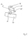
- the guide vanes 50 are stored by blade pin 52, which the blade bearing ring 20th push through axially.
- the guide vanes 50 are non-rotatable connected to the blade journal 52.
- blade levers 54 attached non-rotatably, as can be seen in particular Fig. 2 results.
- the bucket levers 54 have for this purpose a receiving bore 56, with which the blade lever 54 the Bucket pin 52 can be pushed on.
- the twist-proof Fixation takes place in a manner known per se, for example by welding.
- the blade levers 54 each have a lever arm 58, the directed radially outward carries a lever head 60.
- the lever head 60 serves in the manner described in more detail below and Way to, the rotational movement of the adjusting ring 30 on the Transfer guide vane 50. To do this, each lever head is used 60 in a corresponding recess 32 of the adjusting ring 30 and is largely in the tangential direction without play in contact with the corresponding section of the recess 32.
- a rotary movement of the adjusting ring 30, which over the engagement of an adjusting lever, not shown, in a Recess 33 is generated, forcibly coupled leads to one Swiveling of the guide vanes 50.
- the bucket levers take over 54 according to the invention at least one further function, namely those of the support of the adjusting ring 30 in the radial Direction.
- certain sections of the adjustment ring are provided 30 in conjunction with corresponding sections of the Blade lever 54 the function of a radially acting bearing and thus replace the previously usual separate support by means of pins or rollers.
- the adjustment ring 30 can, for example, in the region of the recesses 32 are supported radially, being radial contact surfaces the sections of the circular segment shaped Recesses 33 serve directly.
- the circumferential sections 34 can also be used for this purpose, which are located on the inner circumference between two neighboring ones Recesses 32 are located. In this way, conventional Adjustment rings continue to be used without special measures be, where appropriate on compliance Manufacturing tolerances on those sections must be observed which are to serve as radial contact surfaces.
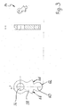
- the lever head 60 is essentially designed as a full circle along a circumferential section 62 is supported in the corresponding recess 32 is. This variant ensures an even radial Support, largely independent of the current one Angular position of the guide vane 50.
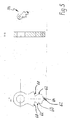
- FIG. 4 A comparable variant is shown in FIG. 4. The difference to the variant described above in that the lever head 60 is flattened, whereby the radial contact surface through two peripheral sections 62 to both Sides of the flattening is formed. In comparison to the variant 3 there are lower frictional forces, which is a reduction enable the actuating forces. However, must a slight deterioration in radial support can be expected.
- FIG. 5 An excellent compromise between the two above
- the embodiment according to FIG. 5 represents variants.
- the blade head 60 is flattened in the radial direction executed, but is in this area radial, semicircular approach 64.
- an additional radial support surface 62 realized without significantly increasing the frictional forces increase.
- the storage properties largely correspond to those the variant according to FIG. 3.
- radial support surfaces can be attached the lever arms 58 in the form of contour sections 68 attached become. Consistent with the exemplary embodiments according to Fig. 3 to Fig. 5 is the attachment of two circular segment-shaped Contour sections 68 that at the transition area too the lever heads 60 are formed.
- the contour sections 68 are used especially for radial support in angular areas outside the middle angular position in which they are on create the peripheral portions 34 of the adjusting ring 30 and thus take over the radial bearing.
- the contour sections 68 can also be specially designed so that independent from the angular position always a radial contact with the peripheral sections 34 is reached.
- the blade levers 54 of the exemplary embodiments according to FIGS. 3 to 5 can still be manufactured as inexpensive stamped parts, with certain circumferential or contour sections as functional surfaces be carried out carefully for radial support have to. Through an appropriate shape - or contouring - it is ensured that the adjusting ring 30 over the Paddle lever 54 rolls. This rolling movement creates a special one low friction.
- blade lever 54 shown a basic form that with those of FIGS. 3 and 4 matches, so that the function of radial support remains unchanged.
- the embodiment is according to the same principle Fig. 7 designed, with a shorter radial extension of the axial guide surfaces 70 is predetermined in that the Lever head 60 is flattened in the radial direction.
- the axial guide surfaces 70 are in this example designed as guide arms that despite reduced Adequate axial guidance of the adjusting ring 30 guarantee.
- Fig. 9 has axial Guide surfaces 70, which are shortened in the radial direction are. Here, too, there is a reduced contact area, however, for the safe axial guidance of the adjusting ring 30 is completely sufficient.
- FIG. 1 A particularly advantageous application is shown in FIG. 1, in which the adjusting ring 30 captively without additional elements is held in that bucket lever 54 with integrated axial guide surfaces 70 are mounted so that the management function is guaranteed on both sides.
- the bucket levers 54 are axial Guide surfaces 70 arranged alternately so that the Adjustment ring 30 distributed over the circumference in the axial direction is performed evenly.
- each side may be sufficient only two or three of the bucket levers 54 with integrated to equip axial guide surfaces 70. Let her through the manufacturing costs of the control apparatus 10 are somewhat reduced.
- axial guide surfaces 70 not as an integral part of the bucket levers 54 to execute, but to execute them as separate components and retrofitted to the blade levers 54, for example by welding, riveting or clamping. This has the advantage that both the blade lever 54 and the axial guide surfaces 70 can be produced as inexpensive stamped parts are.
- FIG. 10 A variant of a diffuser 10 is shown in FIG. 10.
- the adjusting ring 30 is in turn via a bucket lever 54 supported in the radial direction.
- the difference to the previous variants is that the bucket lever 54 axial approaches 66 have the radial bearing function take. In this case too there is a rolling motion between the adjusting ring 30 and the radial bearing surfaces of the Approaches 66 given.
Landscapes
- Engineering & Computer Science (AREA)
- Mechanical Engineering (AREA)
- General Engineering & Computer Science (AREA)
- Chemical & Material Sciences (AREA)
- Chemical Kinetics & Catalysis (AREA)
- General Chemical & Material Sciences (AREA)
- Combustion & Propulsion (AREA)
- Supercharger (AREA)
- Control Of Turbines (AREA)
Priority Applications (4)
| Application Number | Priority Date | Filing Date | Title |
|---|---|---|---|
| DE50209912T DE50209912D1 (de) | 2002-04-26 | 2002-04-26 | Turbokompressor mit verstellbaren Leitschaufeln |
| DE50212520T DE50212520D1 (de) | 2002-04-26 | 2002-04-26 | Turbokompressor mit verstellbaren Leitschaufeln |
| EP02009563A EP1357255B1 (fr) | 2002-04-26 | 2002-04-26 | Turbocompresseur avec distributeur à géométrie variable |
| EP04029659A EP1520959B1 (fr) | 2002-04-26 | 2002-04-26 | Turbocompresseur avec distributeur à géométrie variable |
Applications Claiming Priority (1)
| Application Number | Priority Date | Filing Date | Title |
|---|---|---|---|
| EP02009563A EP1357255B1 (fr) | 2002-04-26 | 2002-04-26 | Turbocompresseur avec distributeur à géométrie variable |
Related Child Applications (1)
| Application Number | Title | Priority Date | Filing Date |
|---|---|---|---|
| EP04029659A Division EP1520959B1 (fr) | 2002-04-26 | 2002-04-26 | Turbocompresseur avec distributeur à géométrie variable |
Publications (2)
| Publication Number | Publication Date |
|---|---|
| EP1357255A1 true EP1357255A1 (fr) | 2003-10-29 |
| EP1357255B1 EP1357255B1 (fr) | 2007-04-11 |
Family
ID=28685915
Family Applications (2)
| Application Number | Title | Priority Date | Filing Date |
|---|---|---|---|
| EP04029659A Expired - Lifetime EP1520959B1 (fr) | 2002-04-26 | 2002-04-26 | Turbocompresseur avec distributeur à géométrie variable |
| EP02009563A Expired - Lifetime EP1357255B1 (fr) | 2002-04-26 | 2002-04-26 | Turbocompresseur avec distributeur à géométrie variable |
Family Applications Before (1)
| Application Number | Title | Priority Date | Filing Date |
|---|---|---|---|
| EP04029659A Expired - Lifetime EP1520959B1 (fr) | 2002-04-26 | 2002-04-26 | Turbocompresseur avec distributeur à géométrie variable |
Country Status (2)
| Country | Link |
|---|---|
| EP (2) | EP1520959B1 (fr) |
| DE (2) | DE50212520D1 (fr) |
Cited By (13)
| Publication number | Priority date | Publication date | Assignee | Title |
|---|---|---|---|---|
| EP1577503A1 (fr) * | 2004-03-08 | 2005-09-21 | BorgWarner Inc. | Turbomachine, aubes de guidage et anneau de montage |
| EP1662094A2 (fr) | 2004-11-30 | 2006-05-31 | BorgWarner Inc. | Turbocompresseur, distributeur pour un turbocompresseur et levier pour un tel distributeur |
| WO2007093407A1 (fr) * | 2006-02-16 | 2007-08-23 | Borgwarner Inc. | Turbocompresseur pourvu d'aubes directrices réglables, d'un levier d'aubes et d'une bague de réglage à cet effet |
| DE102007022356A1 (de) | 2007-05-12 | 2008-11-13 | Mahle International Gmbh | Ladeeinrichtung |
| DE102007052736A1 (de) | 2007-11-06 | 2009-05-07 | Bosch Mahle Turbo Systems Gmbh & Co. Kg | Ladeeinrichtung |
| DE102007055224A1 (de) | 2007-11-19 | 2009-05-20 | Bosch Mahle Turbo Systems Gmbh & Co. Kg | Ladeeinrichtung |
| CN101598037B (zh) * | 2009-06-30 | 2011-08-31 | 康跃科技股份有限公司 | 可变喷嘴零间隙浮动调节装置 |
| CN102667100A (zh) * | 2009-11-27 | 2012-09-12 | 博格华纳公司 | 涡轮增压器 |
| CN102966381A (zh) * | 2011-08-31 | 2013-03-13 | 诺沃皮尼奥内有限公司 | 用于涡轮膨胀器应用的紧凑的igv |
| CN103089344A (zh) * | 2011-11-04 | 2013-05-08 | 萍乡市德博科技发展有限公司 | 拨动盘双向定位叶片双支撑可变截面喷嘴环组件 |
| CN103147846A (zh) * | 2013-03-12 | 2013-06-12 | 汉美综合科技(常州)有限公司 | 用于涡轮增压器的可调式喷嘴 |
| EP3502483A1 (fr) * | 2017-12-19 | 2019-06-26 | Cimos D.D. | Support d'un anneau de synchronisation de turbomachine par des biellettes d'aubes |
| US10927702B1 (en) | 2019-03-30 | 2021-02-23 | Savant Holdings LLC | Turbocharger or turbocharger component |
Families Citing this family (6)
| Publication number | Priority date | Publication date | Assignee | Title |
|---|---|---|---|---|
| EP1811135A1 (fr) | 2006-01-23 | 2007-07-25 | ABB Turbo Systems AG | Dispositif de guidage réglable |
| CN101405479A (zh) * | 2006-03-30 | 2009-04-08 | 博格华纳公司 | 涡轮增压器 |
| CN101191425B (zh) * | 2006-11-25 | 2010-08-18 | 萍乡市德博科技发展有限公司 | 内燃机可变几何涡轮增压器喷嘴环组件 |
| CN100523439C (zh) * | 2007-08-02 | 2009-08-05 | 寿光市康跃增压器有限公司 | 可变截面涡轮增压器的复合喷嘴 |
| DE102009032452A1 (de) | 2009-07-09 | 2011-01-13 | Bosch Mahle Turbo Systems Gmbh & Co. Kg | Ladeeinrichtung |
| DE102011005556A1 (de) * | 2011-03-15 | 2012-09-20 | Bosch Mahle Turbo Systems Gmbh & Co. Kg | Verstellring |
Citations (7)
| Publication number | Priority date | Publication date | Assignee | Title |
|---|---|---|---|---|
| FR1313782A (fr) * | 1961-09-15 | 1963-01-04 | Groupe propulseur à moteur turbo-alimenté | |
| US4179247A (en) * | 1977-01-14 | 1979-12-18 | Wrr Industries, Inc. | Turbocharger having variable area turbine nozzles |
| US4659295A (en) * | 1984-04-20 | 1987-04-21 | The Garrett Corporation | Gas seal vanes of variable nozzle turbine |
| EP0226444A2 (fr) * | 1985-12-11 | 1987-06-24 | AlliedSignal Inc. | Turbosoufflante avec des aubes statoriques variables |
| US4696620A (en) * | 1985-04-17 | 1987-09-29 | Mtu Friedrichshafen Gmbh | Fluid flow machine |
| EP1120547A2 (fr) * | 2000-01-24 | 2001-08-01 | Mitsubishi Heavy Industries, Ltd. | Turbine avec capacité variable |
| DE10050157A1 (de) * | 2000-10-11 | 2002-04-18 | Daimler Chrysler Ag | Leitgitter mit verstellbaren Leitschaufeln für einen Abgasturbolader |
Family Cites Families (6)
| Publication number | Priority date | Publication date | Assignee | Title |
|---|---|---|---|---|
| US2428830A (en) * | 1942-04-18 | 1947-10-14 | Turbo Engineering Corp | Regulation of combustion gas turbines arranged in series |
| US3033519A (en) * | 1958-09-12 | 1962-05-08 | United Aircraft Corp | Turbine nozzle vane construction |
| JP2001329851A (ja) * | 2000-05-19 | 2001-11-30 | Mitsubishi Heavy Ind Ltd | 可変容量タービンの可変ノズル機構 |
| DE10104176A1 (de) * | 2001-01-24 | 2002-07-25 | Mahle Gmbh | Leitschaufelverstelleinrichtung für einen Turbolader |
| US6471470B2 (en) * | 2001-02-26 | 2002-10-29 | Mitsubishi Heavy Industries, Ltd. | Vane adjustment mechanism for variable capacity turbine, and assembling method for the same |
| DE102004057864A1 (de) * | 2004-11-30 | 2006-06-01 | Borgwarner Inc.(N.D.Ges.D.Staates Delaware), Auburn Hills | Abgasturbolader, Leitapparat für einen Abgasturbolader sowie Schaufelhebel für einen Leitapparat |
-
2002
- 2002-04-26 DE DE50212520T patent/DE50212520D1/de not_active Expired - Lifetime
- 2002-04-26 EP EP04029659A patent/EP1520959B1/fr not_active Expired - Lifetime
- 2002-04-26 DE DE50209912T patent/DE50209912D1/de not_active Expired - Lifetime
- 2002-04-26 EP EP02009563A patent/EP1357255B1/fr not_active Expired - Lifetime
Patent Citations (7)
| Publication number | Priority date | Publication date | Assignee | Title |
|---|---|---|---|---|
| FR1313782A (fr) * | 1961-09-15 | 1963-01-04 | Groupe propulseur à moteur turbo-alimenté | |
| US4179247A (en) * | 1977-01-14 | 1979-12-18 | Wrr Industries, Inc. | Turbocharger having variable area turbine nozzles |
| US4659295A (en) * | 1984-04-20 | 1987-04-21 | The Garrett Corporation | Gas seal vanes of variable nozzle turbine |
| US4696620A (en) * | 1985-04-17 | 1987-09-29 | Mtu Friedrichshafen Gmbh | Fluid flow machine |
| EP0226444A2 (fr) * | 1985-12-11 | 1987-06-24 | AlliedSignal Inc. | Turbosoufflante avec des aubes statoriques variables |
| EP1120547A2 (fr) * | 2000-01-24 | 2001-08-01 | Mitsubishi Heavy Industries, Ltd. | Turbine avec capacité variable |
| DE10050157A1 (de) * | 2000-10-11 | 2002-04-18 | Daimler Chrysler Ag | Leitgitter mit verstellbaren Leitschaufeln für einen Abgasturbolader |
Cited By (22)
| Publication number | Priority date | Publication date | Assignee | Title |
|---|---|---|---|---|
| EP1577503A1 (fr) * | 2004-03-08 | 2005-09-21 | BorgWarner Inc. | Turbomachine, aubes de guidage et anneau de montage |
| EP1662094A2 (fr) | 2004-11-30 | 2006-05-31 | BorgWarner Inc. | Turbocompresseur, distributeur pour un turbocompresseur et levier pour un tel distributeur |
| DE102004057864A1 (de) * | 2004-11-30 | 2006-06-01 | Borgwarner Inc.(N.D.Ges.D.Staates Delaware), Auburn Hills | Abgasturbolader, Leitapparat für einen Abgasturbolader sowie Schaufelhebel für einen Leitapparat |
| JP2006161811A (ja) * | 2004-11-30 | 2006-06-22 | Borgwarner Inc | 排気ガスターボチャージャー、排気ガスターボチャージャー用案内装置、及び案内装置用羽根レバー |
| EP1662094A3 (fr) * | 2004-11-30 | 2007-11-14 | BorgWarner Inc. | Turbocompresseur, distributeur pour un turbocompresseur et levier pour un tel distributeur |
| WO2007093407A1 (fr) * | 2006-02-16 | 2007-08-23 | Borgwarner Inc. | Turbocompresseur pourvu d'aubes directrices réglables, d'un levier d'aubes et d'une bague de réglage à cet effet |
| JP2009526939A (ja) * | 2006-02-16 | 2009-07-23 | ボーグワーナー・インコーポレーテッド | 調整可能なガイドブレード、そのためのブレードレバー及び調整リングを含むターボチャージャ |
| US8186944B2 (en) | 2006-02-16 | 2012-05-29 | Borgwarner Inc. | Turbocharger comprising adjustable guide blades, blade lever and adjusting ring therefor |
| DE102007022356A1 (de) | 2007-05-12 | 2008-11-13 | Mahle International Gmbh | Ladeeinrichtung |
| DE102007052736B4 (de) * | 2007-11-06 | 2020-09-03 | BMTS Technology GmbH & Co. KG | Ladeeinrichtung mit einer variablen Turbinen- und/oder Verdichtergeometrie |
| DE102007052736A1 (de) | 2007-11-06 | 2009-05-07 | Bosch Mahle Turbo Systems Gmbh & Co. Kg | Ladeeinrichtung |
| DE102007055224A1 (de) | 2007-11-19 | 2009-05-20 | Bosch Mahle Turbo Systems Gmbh & Co. Kg | Ladeeinrichtung |
| CN101598037B (zh) * | 2009-06-30 | 2011-08-31 | 康跃科技股份有限公司 | 可变喷嘴零间隙浮动调节装置 |
| CN102667100B (zh) * | 2009-11-27 | 2014-10-15 | 博格华纳公司 | 涡轮增压器 |
| CN102667100A (zh) * | 2009-11-27 | 2012-09-12 | 博格华纳公司 | 涡轮增压器 |
| CN102966381A (zh) * | 2011-08-31 | 2013-03-13 | 诺沃皮尼奥内有限公司 | 用于涡轮膨胀器应用的紧凑的igv |
| CN102966381B (zh) * | 2011-08-31 | 2016-06-29 | 诺沃皮尼奥内有限公司 | 用于涡轮膨胀器应用的紧凑的igv |
| US9464533B2 (en) | 2011-08-31 | 2016-10-11 | Nuovo Pignone S.P.A | Compact IGV for turboexpander application |
| CN103089344A (zh) * | 2011-11-04 | 2013-05-08 | 萍乡市德博科技发展有限公司 | 拨动盘双向定位叶片双支撑可变截面喷嘴环组件 |
| CN103147846A (zh) * | 2013-03-12 | 2013-06-12 | 汉美综合科技(常州)有限公司 | 用于涡轮增压器的可调式喷嘴 |
| EP3502483A1 (fr) * | 2017-12-19 | 2019-06-26 | Cimos D.D. | Support d'un anneau de synchronisation de turbomachine par des biellettes d'aubes |
| US10927702B1 (en) | 2019-03-30 | 2021-02-23 | Savant Holdings LLC | Turbocharger or turbocharger component |
Also Published As
| Publication number | Publication date |
|---|---|
| DE50209912D1 (de) | 2007-05-24 |
| EP1357255B1 (fr) | 2007-04-11 |
| DE50212520D1 (de) | 2008-08-28 |
| EP1520959B1 (fr) | 2008-07-16 |
| EP1520959A1 (fr) | 2005-04-06 |
Similar Documents
| Publication | Publication Date | Title |
|---|---|---|
| EP1357255A1 (fr) | Turbocompresseur avec distributeur à géométrie variable | |
| EP2002127B1 (fr) | Dispositif directeur à pré-tourbillonnement | |
| DE102008014678B4 (de) | Turbolader mit einer variablen Turbinengeometrie VTG | |
| DE69921153T2 (de) | Variable ventilsteuerungseinrichtung | |
| EP1662094B1 (fr) | Distributeur pour un turbocompresseur et turbocompresseur | |
| EP1977084B1 (fr) | Dispositif de direction pouvant etre deplace | |
| DE10209484B4 (de) | Turbolader für Fahrzeuge mit verbesserter Aufhängung für den Betätigungsmechanismus der variablen Düsen | |
| DE102010038185B4 (de) | Düseneinrichtung eines Turboladers variabler Geometrie | |
| DE102008007670B4 (de) | Steuerring für VTG | |
| CH703871B1 (de) | Verstellleitapparatanordnung für einen Verdichter. | |
| WO2006060925A1 (fr) | Dispositif directeur pour turbine a gaz d'echappement | |
| EP1977085A1 (fr) | Dispositif de direction pouvant être deplace | |
| EP2006494A1 (fr) | Engrenage pour dispositif de conduite à prérotation | |
| DE60305011T2 (de) | Verbesserte schaufelausführung zur verwendung in turboladern mit variabler geometrie | |
| DE102004043928A1 (de) | Stelleinrichtung für Leitschaufeln eines Abgasturboladers | |
| EP0865566B1 (fr) | Systeme de distribution d'un moteur a combustion interne | |
| EP1387048B1 (fr) | Levier oscillant pour commande de soupape à course variable | |
| EP1205643A1 (fr) | Dispositif d'actionnement de soupapes de moteur à combustion interne | |
| DE10313167B4 (de) | Leitschaufelverstellung für Turbolader mit variabler Turbinengeometrie | |
| DE102010005603B4 (de) | Nockenwellenverstellanordnung mit einem als Wälzlager ausgebildetem Nockenwellenlager | |
| EP1635041B1 (fr) | Callage de superchargeur | |
| DE3885741T2 (de) | Variable steuervorrichtung für den ventilbetrieb einer brennkraftmaschine. | |
| DE10209444A1 (de) | Turbolader für Fahrzeuge mit verbesserter Aufhängung für den Betätigungsmechanismus der variablen Düsen | |
| EP2837779B1 (fr) | Commande de soupape pour une soupape d'échange de gaz d'un moteur à combustion interne | |
| EP1391584B1 (fr) | Turbocompresseur à géométrie variable |
Legal Events
| Date | Code | Title | Description |
|---|---|---|---|
| PUAI | Public reference made under article 153(3) epc to a published international application that has entered the european phase |
Free format text: ORIGINAL CODE: 0009012 |
|
| AK | Designated contracting states |
Kind code of ref document: A1 Designated state(s): AT BE CH CY DE DK ES FI FR GB GR IE IT LI LU MC NL PT SE TR |
|
| AX | Request for extension of the european patent |
Extension state: AL LT LV MK RO SI |
|
| 17P | Request for examination filed |
Effective date: 20031119 |
|
| RAP1 | Party data changed (applicant data changed or rights of an application transferred) |
Owner name: BORGWARNER INC. |
|
| AKX | Designation fees paid |
Designated state(s): DE FR GB IT NL |
|
| RIN1 | Information on inventor provided before grant (corrected) |
Inventor name: JOSEF HEMER Inventor name: LINGENAUBER, ROBERT |
|
| RAP1 | Party data changed (applicant data changed or rights of an application transferred) |
Owner name: BORGWARNER INC. |
|
| GRAP | Despatch of communication of intention to grant a patent |
Free format text: ORIGINAL CODE: EPIDOSNIGR1 |
|
| GRAS | Grant fee paid |
Free format text: ORIGINAL CODE: EPIDOSNIGR3 |
|
| GRAA | (expected) grant |
Free format text: ORIGINAL CODE: 0009210 |
|
| AK | Designated contracting states |
Kind code of ref document: B1 Designated state(s): DE FR GB IT NL |
|
| REG | Reference to a national code |
Ref country code: GB Ref legal event code: FG4D Free format text: NOT ENGLISH |
|
| REF | Corresponds to: |
Ref document number: 50209912 Country of ref document: DE Date of ref document: 20070524 Kind code of ref document: P |
|
| GBT | Gb: translation of ep patent filed (gb section 77(6)(a)/1977) |
Effective date: 20070619 |
|
| ET | Fr: translation filed | ||
| PLBE | No opposition filed within time limit |
Free format text: ORIGINAL CODE: 0009261 |
|
| STAA | Information on the status of an ep patent application or granted ep patent |
Free format text: STATUS: NO OPPOSITION FILED WITHIN TIME LIMIT |
|
| 26N | No opposition filed |
Effective date: 20080114 |
|
| PG25 | Lapsed in a contracting state [announced via postgrant information from national office to epo] |
Ref country code: IT Free format text: LAPSE BECAUSE OF NON-PAYMENT OF DUE FEES Effective date: 20070426 |
|
| PGRI | Patent reinstated in contracting state [announced from national office to epo] |
Ref country code: IT Effective date: 20081001 |
|
| PGRI | Patent reinstated in contracting state [announced from national office to epo] |
Ref country code: IT Effective date: 20081001 |
|
| PGFP | Annual fee paid to national office [announced via postgrant information from national office to epo] |
Ref country code: GB Payment date: 20120327 Year of fee payment: 11 |
|
| PGFP | Annual fee paid to national office [announced via postgrant information from national office to epo] |
Ref country code: NL Payment date: 20120425 Year of fee payment: 11 |
|
| PGFP | Annual fee paid to national office [announced via postgrant information from national office to epo] |
Ref country code: FR Payment date: 20120503 Year of fee payment: 11 |
|
| PGFP | Annual fee paid to national office [announced via postgrant information from national office to epo] |
Ref country code: IT Payment date: 20120419 Year of fee payment: 11 |
|
| REG | Reference to a national code |
Ref country code: NL Ref legal event code: V1 Effective date: 20131101 |
|
| GBPC | Gb: european patent ceased through non-payment of renewal fee |
Effective date: 20130426 |
|
| PG25 | Lapsed in a contracting state [announced via postgrant information from national office to epo] |
Ref country code: GB Free format text: LAPSE BECAUSE OF NON-PAYMENT OF DUE FEES Effective date: 20130426 |
|
| REG | Reference to a national code |
Ref country code: FR Ref legal event code: ST Effective date: 20131231 |
|
| PG25 | Lapsed in a contracting state [announced via postgrant information from national office to epo] |
Ref country code: IT Free format text: LAPSE BECAUSE OF NON-PAYMENT OF DUE FEES Effective date: 20130426 Ref country code: NL Free format text: LAPSE BECAUSE OF NON-PAYMENT OF DUE FEES Effective date: 20131101 Ref country code: FR Free format text: LAPSE BECAUSE OF NON-PAYMENT OF DUE FEES Effective date: 20130430 |
|
| PGFP | Annual fee paid to national office [announced via postgrant information from national office to epo] |
Ref country code: DE Payment date: 20190318 Year of fee payment: 18 |
|
| REG | Reference to a national code |
Ref country code: DE Ref legal event code: R119 Ref document number: 50209912 Country of ref document: DE |
|
| PG25 | Lapsed in a contracting state [announced via postgrant information from national office to epo] |
Ref country code: DE Free format text: LAPSE BECAUSE OF NON-PAYMENT OF DUE FEES Effective date: 20201103 |