EP1357264A2 - Dispositif de réglage d'actionneur électromagnétique de soupape monté dans une culasse de moteur à combustion interne - Google Patents
Dispositif de réglage d'actionneur électromagnétique de soupape monté dans une culasse de moteur à combustion interne Download PDFInfo
- Publication number
- EP1357264A2 EP1357264A2 EP03005289A EP03005289A EP1357264A2 EP 1357264 A2 EP1357264 A2 EP 1357264A2 EP 03005289 A EP03005289 A EP 03005289A EP 03005289 A EP03005289 A EP 03005289A EP 1357264 A2 EP1357264 A2 EP 1357264A2
- Authority
- EP
- European Patent Office
- Prior art keywords
- cylinder head
- cover
- screw
- actuator
- adjusting
- Prior art date
- Legal status (The legal status is an assumption and is not a legal conclusion. Google has not performed a legal analysis and makes no representation as to the accuracy of the status listed.)
- Withdrawn
Links
- 238000002485 combustion reaction Methods 0.000 claims description 5
- 230000037431 insertion Effects 0.000 abstract 1
- 238000003780 insertion Methods 0.000 abstract 1
- 241000237858 Gastropoda Species 0.000 description 1
- 238000010276 construction Methods 0.000 description 1
- 238000004519 manufacturing process Methods 0.000 description 1
- 230000036316 preload Effects 0.000 description 1
- 230000008439 repair process Effects 0.000 description 1
Images

Classifications
-
- F—MECHANICAL ENGINEERING; LIGHTING; HEATING; WEAPONS; BLASTING
- F01—MACHINES OR ENGINES IN GENERAL; ENGINE PLANTS IN GENERAL; STEAM ENGINES
- F01L—CYCLICALLY OPERATING VALVES FOR MACHINES OR ENGINES
- F01L9/00—Valve-gear or valve arrangements actuated non-mechanically
- F01L9/20—Valve-gear or valve arrangements actuated non-mechanically by electric means
-
- F—MECHANICAL ENGINEERING; LIGHTING; HEATING; WEAPONS; BLASTING
- F01—MACHINES OR ENGINES IN GENERAL; ENGINE PLANTS IN GENERAL; STEAM ENGINES
- F01L—CYCLICALLY OPERATING VALVES FOR MACHINES OR ENGINES
- F01L9/00—Valve-gear or valve arrangements actuated non-mechanically
- F01L9/20—Valve-gear or valve arrangements actuated non-mechanically by electric means
- F01L9/21—Valve-gear or valve arrangements actuated non-mechanically by electric means actuated by solenoids
- F01L2009/2132—Biasing means
- F01L2009/2134—Helical springs
- F01L2009/2136—Two opposed springs for intermediate resting position of the armature
-
- F—MECHANICAL ENGINEERING; LIGHTING; HEATING; WEAPONS; BLASTING
- F01—MACHINES OR ENGINES IN GENERAL; ENGINE PLANTS IN GENERAL; STEAM ENGINES
- F01L—CYCLICALLY OPERATING VALVES FOR MACHINES OR ENGINES
- F01L2301/00—Using particular materials
-
- F—MECHANICAL ENGINEERING; LIGHTING; HEATING; WEAPONS; BLASTING
- F01—MACHINES OR ENGINES IN GENERAL; ENGINE PLANTS IN GENERAL; STEAM ENGINES
- F01L—CYCLICALLY OPERATING VALVES FOR MACHINES OR ENGINES
- F01L2303/00—Manufacturing of components used in valve arrangements
- F01L2303/01—Tools for producing, mounting or adjusting, e.g. some part of the distribution
Definitions
- the invention relates to a preamble of claim 1 Device for adjusting in a cylinder head of an internal combustion engine arranged stroke actuator for a gas exchange valve, the one below Lid of the cylinder head arranged in this actuator between stroke-spaced Electromagnet includes armature guided armature, which in Rest position by means of a closing spring and a diametrically effective opening spring is held in a central position, which is in a yoke close to the cover of the actuator acting on the opening spring and a receptacle is adjustable for a set screw having an adjusting tool.
- Such a device is known for example from DE 196 31 909 A1. Assuming that the aforementioned closing spring and the aforementioned opening spring are identical in their characteristics can with this known device a set screw to adjust the respective spring preload exact geometric center position of the armature between the pole faces of the stroke-spaced Electromagnets can be set.
- a disadvantage of this known device is that to set the exact Middle position of the armature of a stroke actuator that closes off the control chamber in the cylinder head Lid must be removed, which is particularly due to the area of the cover of the cylinder head arranged auxiliary devices of the internal combustion engine can be labor intensive.
- the invention is therefore based on the object of a generic adjustment device to further develop such that disassembly for centering a stroke actuator or removing the cover from the cylinder head is unnecessary.
- An advantageous embodiment of the invention in terms of simple construction is in further achieved in that with a hexagon socket as a tool holder provided set screw in a protruding the yoke cover side Threaded section is equipped with a lock nut, the outer circumference with a tooth profile is provided for engaging a motor or manually driven Ritzels, which has another opening in the cylinder head cover toothed lock nut can be fed, the engagement of the with a drive shaft connected pinion in the lock nut tooth profile via a in a blind hole guide pin guided in the actuator yoke is secured.
- each Stroke actuator for an adjusting tool engaging the adjusting screw on the one hand and for a counter tool to secure the set screw on the other hand
- the adjusting tool with the center position adjusted of the stroke actuator held the set screw positioned during the counter can be, for which in particular an angled socket wrench an external hex to engage the internal hex of the set screw best suited.
- the equivalent is also an angled screwdriver, which engages in a slot in the set screw.
- Angled positioning tools To secure the adjustment position reached are both carried out for a motor Counter in the basic setting of the internal combustion engine on the production line as well as for a manual counterattack in the event of repairs and overhauls.
- An additional embodiment of the invention is in a further subclaim described, according to which a section with the cover-side yoke connected screw-in section for the set screw slotted in the screw-in direction is with clamping tabs arranged on both sides of the slot by a are firmly interspersed on one of the clamping tabs, the carries a worm wheel serving as a tension nut in the free threaded part one arranged on a drive shaft in a rotationally fixed manner and via a further opening in the cylinder head cover feed screw in drive connection can be brought, a track pin provided in the free end region of the drive shaft in a blind hole in the actuator yoke the engagement of the Secures snail in the worm wheel.
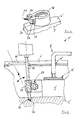
- a device 1 for adjusting one in a cylinder head 2, not shown Internal combustion engine arranged actuator 3 for a not shown Gas exchange valve is used at a below a cover 4 of the cylinder head 2 in this arranged actuator 3, a not shown, between stroke-spaced Electromagnets guided armature to drive a Gas exchange valve to a gas exchange duct 5 in arranged in the cylinder head 2 Adjust the middle position between the aforementioned electromagnets.
- anchor is in the rest position by means of a closing spring and a diametrically effective arranged opening spring of the stroke actuator 3 held in a central position, which on a in a yoke 6 near the cover of the actuator 3 on the opening spring interactively arranged and having a receptacle 7 for an adjusting tool 8 Set screw 9 is adjustable.
- the adjusting device 1 is designed in such a way that one with the Tool holder 7 of the set screw 8 aligned opening 10 provided in the cover 4 remaining on the cylinder head 2 during adjustment is for feeding the adjusting tool 8 to the adjusting screw 9.
- the adjusting device 1 is with an internal hexagon provided as a tool holder 7 set screw 9 in a threaded section 90 projecting beyond the yoke 6 of the actuator 3 on the cover side equipped with a lock nut 11, the outer circumference with a tooth profile 12th is provided for engaging a motor-driven or manually driven pinion 13.
- This pinion 13 is via a further opening 14 in the cylinder head cover 4 the toothed lock nut 11 can be fed, the engagement of the with a drive shaft 15 connected pinion 13 in the lock nut tooth profile 12 via a in a blind hole 16 in the actuator yoke 6 guided guide pin 17 secured is.
- the adjusting tool 8 for engagement in the hexagon socket of the adjusting screw 9 an angled section on to counter the set screw 9 by means of the driven pinion to the position of the set Middle position of the armature, not shown, between the two electromagnets to back up.
- FIGS. 3 and 4 Another embodiment of the adjusting device 1 'according to FIGS. 3 and 4 shows that a section connected to the yoke 6 'of the actuator 3' on the cover side Screw-in section 18 for the set screw 9 'in the screw-in direction is slotted with tension tabs 20 arranged on both sides of the slot 19 from a clamping screw 21 fixedly arranged on one of the clamping lugs 20 are interspersed in the free threaded part 22 serving as a clamping nut Worm gear 23 carries.
- the worm wheel 23 is on a drive shaft 24 non-rotatably arranged and via a further opening 14 'in the cylinder head cover 4 'feedable screw 25 can be brought into drive connection, one in the free end region of the drive shaft 24 provided in 26 one Blind hole 27 in the actuator yoke 6 'guided the engagement of the worm 25 in the worm wheel 23 secures.
- each cylinder head cover 4, 4 ' can be closed by means of elastic caps, not shown.
- a stroke actuator 3 or 3 ' without removing the respective cylinder head cover 4 or 4 'by feeding an adjusting tool 8 or 8' to the respective adjusting screw 9 or 9 'on the one hand and by supplying a handling tool for securing the adjusting screw 9 or 9 'on the other hand via the in the respective cover 4, 4' provided openings 10, 14 and 10 ', 14' without dismantling the cylinder head cover 4 or 4 'to adjust.
Landscapes
- Engineering & Computer Science (AREA)
- Mechanical Engineering (AREA)
- General Engineering & Computer Science (AREA)
- Valve Device For Special Equipments (AREA)
Applications Claiming Priority (2)
| Application Number | Priority Date | Filing Date | Title |
|---|---|---|---|
| DE10218737 | 2002-04-26 | ||
| DE10218737A DE10218737A1 (de) | 2002-04-26 | 2002-04-26 | Vorrichtung zum Justieren eines in einem Zylinderkopf einer Brennkraftmaschine angeordneten Hubaktuators für ein Gaswechselventil |
Publications (1)
| Publication Number | Publication Date |
|---|---|
| EP1357264A2 true EP1357264A2 (fr) | 2003-10-29 |
Family
ID=28685307
Family Applications (1)
| Application Number | Title | Priority Date | Filing Date |
|---|---|---|---|
| EP03005289A Withdrawn EP1357264A2 (fr) | 2002-04-26 | 2003-03-11 | Dispositif de réglage d'actionneur électromagnétique de soupape monté dans une culasse de moteur à combustion interne |
Country Status (2)
| Country | Link |
|---|---|
| EP (1) | EP1357264A2 (fr) |
| DE (1) | DE10218737A1 (fr) |
Cited By (2)
| Publication number | Priority date | Publication date | Assignee | Title |
|---|---|---|---|---|
| FR2870563A1 (fr) * | 2004-05-19 | 2005-11-25 | Peugeot Citroen Automobiles Sa | Dispositif d'actionnement de soupapes |
| FR2870564A1 (fr) * | 2004-05-19 | 2005-11-25 | Peugeot Citroen Automobiles Sa | Dispositif d'actionnement de soupapes |
Citations (1)
| Publication number | Priority date | Publication date | Assignee | Title |
|---|---|---|---|---|
| DE19631909A1 (de) | 1995-08-08 | 1997-02-13 | Fev Motorentech Gmbh & Co Kg | Verfahren zur Justierung der Ruhelage des Ankers an einem elektromganetischen Aktuator |
Family Cites Families (1)
| Publication number | Priority date | Publication date | Assignee | Title |
|---|---|---|---|---|
| DE20115060U1 (de) * | 2001-09-12 | 2002-01-31 | TRW Deutschland GmbH, 30890 Barsinghausen | Nockenwellenloser Aktuator für Betätigung eines Hubventils |
-
2002
- 2002-04-26 DE DE10218737A patent/DE10218737A1/de not_active Withdrawn
-
2003
- 2003-03-11 EP EP03005289A patent/EP1357264A2/fr not_active Withdrawn
Patent Citations (1)
| Publication number | Priority date | Publication date | Assignee | Title |
|---|---|---|---|---|
| DE19631909A1 (de) | 1995-08-08 | 1997-02-13 | Fev Motorentech Gmbh & Co Kg | Verfahren zur Justierung der Ruhelage des Ankers an einem elektromganetischen Aktuator |
Cited By (6)
| Publication number | Priority date | Publication date | Assignee | Title |
|---|---|---|---|---|
| FR2870563A1 (fr) * | 2004-05-19 | 2005-11-25 | Peugeot Citroen Automobiles Sa | Dispositif d'actionnement de soupapes |
| FR2870564A1 (fr) * | 2004-05-19 | 2005-11-25 | Peugeot Citroen Automobiles Sa | Dispositif d'actionnement de soupapes |
| WO2005112543A1 (fr) * | 2004-05-19 | 2005-12-01 | Peugeot Citroen Automobiles | Dispositif d'actionnement de soupapes |
| WO2005113946A1 (fr) * | 2004-05-19 | 2005-12-01 | Peugeot Citroen Automobiles | Dispositif d'actionnement de soupapes |
| US7540265B2 (en) | 2004-05-19 | 2009-06-02 | Peugeot Citroen Automobiles Sa | Valve actuating device |
| US7654235B2 (en) | 2004-05-19 | 2010-02-02 | Peugeot Citroen Automobiles Sa | Valve actuating device |
Also Published As
| Publication number | Publication date |
|---|---|
| DE10218737A1 (de) | 2003-12-11 |
Similar Documents
| Publication | Publication Date | Title |
|---|---|---|
| DE4219956C2 (de) | Schneideinrichtung für eine Motorkettensäge | |
| DE3442409A1 (de) | Motorgetriebenes ventil-betaetigungsglied | |
| EP1332023A1 (fr) | Machine-outil a main comportant au moins une poignee | |
| DE102014206862A1 (de) | Baugruppe eines Fahrzeugsitzes mit einer Befestigungseinrichtung | |
| DE102005004000A1 (de) | Mitnehmer | |
| EP1585912A1 (fr) | Unite modulaire munie d'un manchon pour transmission par chaine | |
| DE102004051424B4 (de) | Vorrichtung zur Nockenwellenverstellung einer Brennkraftmaschine und Montagewerkzeug | |
| EP1357264A2 (fr) | Dispositif de réglage d'actionneur électromagnétique de soupape monté dans une culasse de moteur à combustion interne | |
| DE102004035077A1 (de) | Verfahren zum Einstellen einer Nockenwellenverstelleinrichtung für Brennkraftmaschinen von Kraftfahrzeugen sowie Vorrichtung zur Durchführung des Verfahrens | |
| DE3133652A1 (de) | Antrieb zum verstellen eines gefuehrten bauelements | |
| CH712345A2 (de) | Vorrichtung zur Positionierung einer Halteeinrichtung für eine Schraubenverbindung bei Überkopfmontage und -demontage. | |
| DE102021123121A1 (de) | Werkstückanschlag und Spannvorrichtung mit Werkstückanschlag | |
| DE10031610A1 (de) | Kettenspanner | |
| EP0068337B1 (fr) | Culbuteur pour commander les soupapes de moteurs à combustion interne | |
| DE102023116740B3 (de) | Handhaltbare Zug- und Druckvorrichtung sowie Hydraulikaktuator | |
| DE20316281U1 (de) | Vorrichtung zur Einstellung und Arretierung von Nockenwellen | |
| EP1146205B1 (fr) | Actionneur électromagnétique avec un capuchon de ressort pour la commande d'une soupape de moteur à combusion | |
| AT408529B (de) | Positioniervorrichtung für einen schweissbrenner | |
| DE102005023644A1 (de) | Schraubverbindung zwischen Türscharnier und Türrahmen bei einem Kraftfahrzeug | |
| DE20208594U1 (de) | Spannfutter für Werkzeugköpfe | |
| EP1724427A2 (fr) | Dispositif de réglage de la position d'un rail de guidage d'un lève-vitre | |
| DE202014008469U1 (de) | Antriebseinheit für ein Kraftfahrzeug mit einer Nockenwellenverstelleinrichtung | |
| DE102023112864A1 (de) | Beschlag für Türen oder Fenster | |
| DE102013112323A1 (de) | Schraubwerkzeug mit Einpresskraftbegrenzung | |
| DE10208069C1 (de) | Stellgetriebe |
Legal Events
| Date | Code | Title | Description |
|---|---|---|---|
| PUAI | Public reference made under article 153(3) epc to a published international application that has entered the european phase |
Free format text: ORIGINAL CODE: 0009012 |
|
| AK | Designated contracting states |
Kind code of ref document: A2 Designated state(s): AT BE BG CH CY CZ DE DK EE ES FI FR GB GR HU IE IT LI LU MC NL PT RO SE SI SK TR |
|
| AX | Request for extension of the european patent |
Extension state: AL LT LV MK |
|
| STAA | Information on the status of an ep patent application or granted ep patent |
Free format text: STATUS: THE APPLICATION IS DEEMED TO BE WITHDRAWN |
|
| 18D | Application deemed to be withdrawn |
Effective date: 20061003 |