EP1357301A2 - Befestigungsanordnung für Isolierplatten - Google Patents
Befestigungsanordnung für Isolierplatten Download PDFInfo
- Publication number
- EP1357301A2 EP1357301A2 EP03405251A EP03405251A EP1357301A2 EP 1357301 A2 EP1357301 A2 EP 1357301A2 EP 03405251 A EP03405251 A EP 03405251A EP 03405251 A EP03405251 A EP 03405251A EP 1357301 A2 EP1357301 A2 EP 1357301A2
- Authority
- EP
- European Patent Office
- Prior art keywords
- insulating plate
- nail
- shaft
- clamping
- area
- Prior art date
- Legal status (The legal status is an assumption and is not a legal conclusion. Google has not performed a legal analysis and makes no representation as to the accuracy of the status listed.)
- Granted
Links
- 239000000463 material Substances 0.000 claims abstract description 28
- 239000007787 solid Substances 0.000 claims abstract description 18
- 238000003801 milling Methods 0.000 claims description 19
- 230000008878 coupling Effects 0.000 claims description 12
- 238000010168 coupling process Methods 0.000 claims description 12
- 238000005859 coupling reaction Methods 0.000 claims description 12
- 239000011810 insulating material Substances 0.000 claims description 12
- 229910000831 Steel Inorganic materials 0.000 claims description 5
- 239000010959 steel Substances 0.000 claims description 5
- 239000004575 stone Substances 0.000 claims description 4
- 230000001681 protective effect Effects 0.000 claims description 3
- 238000001746 injection moulding Methods 0.000 claims description 2
- 241000587161 Gomphocarpus Species 0.000 claims 1
- 238000007599 discharging Methods 0.000 claims 1
- 230000035515 penetration Effects 0.000 claims 1
- 238000004873 anchoring Methods 0.000 description 8
- 230000000694 effects Effects 0.000 description 5
- 238000004519 manufacturing process Methods 0.000 description 4
- 238000003780 insertion Methods 0.000 description 3
- 230000037431 insertion Effects 0.000 description 3
- 230000001788 irregular Effects 0.000 description 3
- 238000005516 engineering process Methods 0.000 description 2
- 230000002093 peripheral effect Effects 0.000 description 2
- 239000000853 adhesive Substances 0.000 description 1
- 230000001070 adhesive effect Effects 0.000 description 1
- 239000012790 adhesive layer Substances 0.000 description 1
- 238000005452 bending Methods 0.000 description 1
- 239000003795 chemical substances by application Substances 0.000 description 1
- 230000001419 dependent effect Effects 0.000 description 1
- 238000005553 drilling Methods 0.000 description 1
- 238000003384 imaging method Methods 0.000 description 1
- 238000005192 partition Methods 0.000 description 1
- 230000000704 physical effect Effects 0.000 description 1
- 238000000926 separation method Methods 0.000 description 1
- 239000007921 spray Substances 0.000 description 1
- 238000005507 spraying Methods 0.000 description 1
Images


Classifications
-
- F—MECHANICAL ENGINEERING; LIGHTING; HEATING; WEAPONS; BLASTING
- F16—ENGINEERING ELEMENTS AND UNITS; GENERAL MEASURES FOR PRODUCING AND MAINTAINING EFFECTIVE FUNCTIONING OF MACHINES OR INSTALLATIONS; THERMAL INSULATION IN GENERAL
- F16B—DEVICES FOR FASTENING OR SECURING CONSTRUCTIONAL ELEMENTS OR MACHINE PARTS TOGETHER, e.g. NAILS, BOLTS, CIRCLIPS, CLAMPS, CLIPS OR WEDGES; JOINTS OR JOINTING
- F16B13/00—Dowels or other devices fastened in walls or the like by inserting them in holes made therein for that purpose
- F16B13/04—Dowels or other devices fastened in walls or the like by inserting them in holes made therein for that purpose with parts gripping in the hole or behind the reverse side of the wall after inserting from the front
-
- B—PERFORMING OPERATIONS; TRANSPORTING
- B23—MACHINE TOOLS; METAL-WORKING NOT OTHERWISE PROVIDED FOR
- B23B—TURNING; BORING
- B23B51/00—Tools for drilling machines
- B23B51/04—Drills for trepanning
- B23B51/0426—Drills for trepanning with centering devices
-
- B—PERFORMING OPERATIONS; TRANSPORTING
- B23—MACHINE TOOLS; METAL-WORKING NOT OTHERWISE PROVIDED FOR
- B23B—TURNING; BORING
- B23B51/00—Tools for drilling machines
- B23B51/04—Drills for trepanning
- B23B51/0473—Details about the connection between the driven shaft and the tubular cutting part; Arbors
-
- E—FIXED CONSTRUCTIONS
- E04—BUILDING
- E04B—GENERAL BUILDING CONSTRUCTIONS; WALLS, e.g. PARTITIONS; ROOFS; FLOORS; CEILINGS; INSULATION OR OTHER PROTECTION OF BUILDINGS
- E04B1/00—Constructions in general; Structures which are not restricted either to walls, e.g. partitions, or floors or ceilings or roofs
- E04B1/62—Insulation or other protection; Elements or use of specified material therefor
- E04B1/74—Heat, sound or noise insulation, absorption, or reflection; Other building methods affording favourable thermal or acoustical conditions, e.g. accumulating of heat within walls
- E04B1/76—Heat, sound or noise insulation, absorption, or reflection; Other building methods affording favourable thermal or acoustical conditions, e.g. accumulating of heat within walls specifically with respect to heat only
- E04B1/762—Exterior insulation of exterior walls
- E04B1/7629—Details of the mechanical connection of the insulation to the wall
- E04B1/7633—Dowels with enlarged insulation retaining head
-
- E—FIXED CONSTRUCTIONS
- E04—BUILDING
- E04F—FINISHING WORK ON BUILDINGS, e.g. STAIRS, FLOORS
- E04F13/00—Coverings or linings, e.g. for walls or ceilings
- E04F13/07—Coverings or linings, e.g. for walls or ceilings composed of covering or lining elements; Sub-structures therefor; Fastening means therefor
- E04F13/08—Coverings or linings, e.g. for walls or ceilings composed of covering or lining elements; Sub-structures therefor; Fastening means therefor composed of a plurality of similar covering or lining elements
- E04F13/0801—Separate fastening elements
- E04F13/0832—Separate fastening elements without load-supporting elongated furring elements between wall and covering elements
- E04F13/0833—Separate fastening elements without load-supporting elongated furring elements between wall and covering elements not adjustable
- E04F13/0835—Separate fastening elements without load-supporting elongated furring elements between wall and covering elements not adjustable the fastening elements extending into the back side of the covering elements
-
- F—MECHANICAL ENGINEERING; LIGHTING; HEATING; WEAPONS; BLASTING
- F16—ENGINEERING ELEMENTS AND UNITS; GENERAL MEASURES FOR PRODUCING AND MAINTAINING EFFECTIVE FUNCTIONING OF MACHINES OR INSTALLATIONS; THERMAL INSULATION IN GENERAL
- F16B—DEVICES FOR FASTENING OR SECURING CONSTRUCTIONAL ELEMENTS OR MACHINE PARTS TOGETHER, e.g. NAILS, BOLTS, CIRCLIPS, CLAMPS, CLIPS OR WEDGES; JOINTS OR JOINTING
- F16B13/00—Dowels or other devices fastened in walls or the like by inserting them in holes made therein for that purpose
- F16B13/02—Dowels or other devices fastened in walls or the like by inserting them in holes made therein for that purpose in one piece with protrusions or ridges on the shaft
-
- F—MECHANICAL ENGINEERING; LIGHTING; HEATING; WEAPONS; BLASTING
- F16—ENGINEERING ELEMENTS AND UNITS; GENERAL MEASURES FOR PRODUCING AND MAINTAINING EFFECTIVE FUNCTIONING OF MACHINES OR INSTALLATIONS; THERMAL INSULATION IN GENERAL
- F16B—DEVICES FOR FASTENING OR SECURING CONSTRUCTIONAL ELEMENTS OR MACHINE PARTS TOGETHER, e.g. NAILS, BOLTS, CIRCLIPS, CLAMPS, CLIPS OR WEDGES; JOINTS OR JOINTING
- F16B13/00—Dowels or other devices fastened in walls or the like by inserting them in holes made therein for that purpose
- F16B13/04—Dowels or other devices fastened in walls or the like by inserting them in holes made therein for that purpose with parts gripping in the hole or behind the reverse side of the wall after inserting from the front
- F16B13/08—Dowels or other devices fastened in walls or the like by inserting them in holes made therein for that purpose with parts gripping in the hole or behind the reverse side of the wall after inserting from the front with separate or non-separate gripping parts moved into their final position in relation to the body of the device without further manual operation
- F16B13/0891—Dowels or other devices fastened in walls or the like by inserting them in holes made therein for that purpose with parts gripping in the hole or behind the reverse side of the wall after inserting from the front with separate or non-separate gripping parts moved into their final position in relation to the body of the device without further manual operation with a locking element, e.g. wedge, key or ball moving along an inclined surface of the dowel body
-
- F—MECHANICAL ENGINEERING; LIGHTING; HEATING; WEAPONS; BLASTING
- F16—ENGINEERING ELEMENTS AND UNITS; GENERAL MEASURES FOR PRODUCING AND MAINTAINING EFFECTIVE FUNCTIONING OF MACHINES OR INSTALLATIONS; THERMAL INSULATION IN GENERAL
- F16B—DEVICES FOR FASTENING OR SECURING CONSTRUCTIONAL ELEMENTS OR MACHINE PARTS TOGETHER, e.g. NAILS, BOLTS, CIRCLIPS, CLAMPS, CLIPS OR WEDGES; JOINTS OR JOINTING
- F16B13/00—Dowels or other devices fastened in walls or the like by inserting them in holes made therein for that purpose
- F16B13/12—Separate metal or non-separate or non-metal dowel sleeves fastened by inserting the screw, nail or the like
- F16B13/128—Separate metal or non-separate or non-metal dowel sleeves fastened by inserting the screw, nail or the like with extending protrusions, e.g. discs, segments, ridges, fingers or tongues
-
- B—PERFORMING OPERATIONS; TRANSPORTING
- B23—MACHINE TOOLS; METAL-WORKING NOT OTHERWISE PROVIDED FOR
- B23B—TURNING; BORING
- B23B2226/00—Materials of tools or workpieces not comprising a metal
- B23B2226/75—Stone, rock or concrete
Definitions
- the invention relates to a fastening arrangement for insulating plates, a Insulating plate nail for this mounting arrangement and a tool for Production of a mounting hole for such an insulating plate nail.
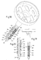
- FIGS. 1 and 2 illustrate, is to be introduced an insulating plate nail 1 in a clad by an insulating material plate 2 Building wall 3 initially a stepped receiving bore 4 by means of a Tool 5 made in one operation, based on that later 18 to 20 is described in more detail.
- the receiving bore 4 extends different from that provided for receiving the flange-like holding head 6, outer countersunk hole 7 with the same diameter of e.g. 10 mm with one sufficient length to accommodate the nail shaft 8, which corresponds to the thickness the insulating material plate 2 and one for anchoring in the solid Wall material 9 corresponds to the required drilling depth.
- the nail shaft 8 has one for clamping anchoring in the solid wall material 9 executed anchor area 10 to which one for the recording Connects holding shaft part 11 provided in the insulating material.
- This has one Diameter or a largest transverse extension that is somewhat larger as the bore diameter of the receiving bore 4 in the area concerned, so that when pressed into the mounting hole with elastic Bias is included in the material of the insulating material plate 2.
- the length of the holding shaft part 11 is the thickness of the insulating material plate 2 adapted that the adjoining anchor area 10 of the nail shaft 8 from the front nail end 12 at least to the e.g. an adhesive layer having separating plane 13 between the solid wall material receiving it 9 and the insulating material plate 2 extends and, for example, accordingly the illustrated embodiment also bridges this.
- the front anchor means 14 are in the embodiments of the Fig. 2 to 17 of the same design and have at least one over a band part 17, 18 on the nail shaft wedge element 19, 20, which is in engagement contact bears on a wedge surface 21, 22 of the nail shaft 8. With several such Wedge elements 19, 20 are on two diametrically opposite one another Sides of the nail shaft 8 are provided and in the longitudinal direction to each other added. Tensile forces acting on the insulating plate nail 1 thus effect a wedge bracing in the area of their arrangement in the receiving bore 4.
- Anchoring agents with a comparable wedge effect are per se known by DE 4312339.
- an insulating plate nail 1 according to the present Invention results for anchoring the insulating plate nail without play 1 required clamping of the wedge elements due to the elasticity the insulating material plate 2, by pressing in the insulating plate nail something is compressed elastically and then through Springback on the insulating plate nail 1 is suitable for its bracing Exerts traction.
- the outer surface comes to bear against the bore surface the wedge elements 19, 20 an engagement-improving, e.g. out numerous existing in the circumferential direction of the plate nail 1 ribs Fine profiling, as in the embodiment of FIGS. 20 and 21 you can see.
- the clamping area 15 adjoining the front anchor means is in the embodiment of FIGS. 2 to 13 by an elastically compressible Shaft extension 23 formed, the two diametrically to each other arranged, arched away from each other like a bridge, one between them Has recess 24 including web parts 25,26.
- the bridge-like Web parts 25, 26 go over two axially opposed, conically beveled end regions 27, 28 to form a cylindrical one Area of the nail shaft over whose diameter is at least approximated corresponds to that of the receiving bore 4.
- Such a clamping area 15 ensures its arrangement in the vicinity of the parting plane 13 a play-free attachment an insulating plate 2 even when the front anchor means 14 due to the structure of the solid wall material 9 on a cavity 16 are arranged on which their wedge elements 19, 20 cannot take effect.
- the outer surface of the solid wall material 9 has the insulating plate nail 1 at its rear end flange-like a plate-shaped holding head 35, the is enclosed in the countersunk hole 7 of the insulating plate 2.
- the holding head 35 has a holding plate 36, preferably integrally formed on the nail shaft 8, the cavity bounded by a peripheral edge 37 a socket for the lower, cylindrical region 38 of a round plate 39 made of insulating material forms. This ensures on the outer surface 40 of the insulated building wall 3 uniform physical properties.
- the rondelle 39 In addition to one Press fit in the holding plate 36 provided for the rondelle 39 are for their Fastening to the bottom wall 41 thereof a plurality of adhesive pins 42 ending in a point provided that when pressing the Rondelle 39 in its relatively soft Dig in material. Adjacent to the cylindrical, for inclusion in the area 38 provided the holding plate 36, the rondelle 39 passes over a conical intermediate region 43 into an outer cylindrical region 44 about whose diameter is slightly larger than that of the countersunk hole 7 Insulating plate 2 so that the rondelle 39 is firmly seated. In the bottom wall 41 provided recesses 34 serve to reduce the cost of materials in the production of the insulating plate nail using plastic spraying technology.
- the insulating plate nail of the embodiment according to FIGS. 7 to 10 has one Nail shaft 45 with an anchor area 46, which has a predetermined breaking point acting, film-like, thin wall part 47 with a holding shaft part 48 is connected, so that this when the insulating plate nail is pressed in pushes a receiving hole 4 telescopically into the anchor area 46 and therein jammed.
- 9 shows the relevant initial state of the insulating plate nail, while Fig.10 the insulating plate nail in fully anchored End position.
- a clamping area 49 is provided, which in its embodiment with the clamping area 15 of the front anchor means 14 of the embodiment the Fig.2 -6 is comparable.
- FIGS. 11 and 12 show two variants for the Execution of a holding shaft part 50 or 51.
- the holding shaft part 50 according to Fig.11 has a cross-shaped cross section with four at an angle of 90 ° mutually spaced longitudinal ribs 52-54 which pass through between them arranged angle parts 55 are connected to one another in the circumferential direction.
- the holding shaft part 51 consists of a relatively thin-walled sleeve 56 Plastic, in which a steel pin 57 is enclosed to increase its bending stiffness is.
- the steel pin 57 is on for the connection between the two its front end portion 58 provided with a profile 59, which by a narrowed area 60 of the part of the nail shaft made of plastic is included.
- the front end region 58 is between the two web parts 61, 62 of the clamping area 63 on part of it Included circumferentially and clamped accordingly, while the rear provided head 64 of the steel pin 57 of the distanced support of the steel pin 57 on the inside of a short sleeve extension 65 serves.
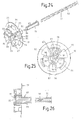
- FIGS. 18 to 23 differ from those of FIGS. 2 to 6 and 11 to 13 and others. thereby, that front-side anchor means are the same as the adjoining one Clamping area are executed and pass into this, so that the anchor area 98 extends from the nail tip 99 to the holding shaft part 100.
- two are in each case over outer clamping elements extending a larger part of the anchor area 98 101, 102 and 103, 104 on both sides to a central shaft region 105 or 106 arranged and only at their ends via web parts 107, 108 or 109, 110 with the central shaft region 105 or 106 elastically connected.
- the clamping effect of the elongated clamping elements 101,102 or 103,104 results from a tooth-row arrangement of wedge surfaces 113 and 114 on the inside of the clamping elements 100, 101 or 103, 104, which on wedge surfaces which run correspondingly in rows of teeth 118 and 119 on both sides of the central shaft area 105 and 106 concerns.
- wedge surfaces 113 or 114 and 118 and 119 In order to shift these wedge surfaces 113 or 114 and 118 and 119 to counteract each other, they have preferably a symmetrical, flat v-shaped cross section, as in the Cross-sectional view of Figure 23 can be seen, or they are each on the one hand flat concave and, on the other hand, correspondingly flat convex symmetrical curved.
- the insulating plate To release 2 from the solid wall material 9, the central shaft area moves 105 or 106 to the outside or in the illustration of FIG. 20 to the outside above, so that the anchor hole on the inner surface of the receiving bore 4 standing, elongated clamping elements 101, 102 and 103, 104 by the Radial wedge action of the rows of wedge surfaces 113 or 114 and 118 or 119 are pressed outwards and the anchor contact changes accordingly strengthened.
- the embodiment of Fig. 18 to 20 has in addition to the two elongated clamping elements having a plurality of inner wedge surfaces 113 101, 102 further clamping elements 120 to 123, each with only one inner one Wedge surface 124, as is also e.g. the embodiment of Fig.16 shows, so that on the additional clamping elements 120 to 123 further cam extensions 125, 126 are present.
- the recesses thus available between successive clamping elements can be adjusted on an irregular inner surface of the receiving bore 4 may be advantageous.
- the wedges 113 and 114 are to be assigned to one another following areas of the clamping elements 101, 102 and 120 to 123 or 103, 104 with a e.g. low by a few tenths of a millimeter each graduated diameter referring to the insulating plate nail 1, so that the anchor area 98 of the insulating plate nail 1 is directed towards Nail tip 99 slightly tapered. This makes it easier to insert into a mounting hole 4 with subsequent firm jamming with the bore wall.
- the insulating plate nails of the exemplary embodiments in FIG. 18 have and 21 on their central shaft region 105 and 106, respectively, in arrangement with the Clamping elements 101, 102 and 120 to 123 or 103, 104 in the circumferential direction of the nail offset by 90 degrees, a sawtooth-like row of engagement teeth 132 or 133, which contribute to anchoring in the receiving bore 4.
- the coupling between the milling head 79 and the coupling sleeve 78 is done by hexagonal engagement between an inner one Hexagonal cross-section hub part 82 of the milling head 79 and Coupling sleeve 78, wherein longitudinal slots provided in the coupling sleeve 78 84 ensure a resilient engagement contact.
- the milling head 79 is in one piece using spray technology, e.g. made of a plastic material manufactured. His intended for the milling of the cylindrical countersunk hole 7, sawtooth-shaped milling teeth 84 are on arcuate sector parts 85 provided.
- the sector parts 85 are each by two radial webs 86 and 87 limited, one of which has a row of teeth on its free edge 88, which milled out the insulating material of the insulating plate 2 the countersunk hole 7, until the bottom surface 89 thereof is milled out.
- the Sector parts 85 and the radial webs 86, 87 are at a limit of the milling depth Washer 90 integrally formed, which has a plurality of openings 91,92 around which to be able to discharge milled material to the outside.
- the considerable size these openings also contribute to material savings in the manufacture of the Milling head 79 in plastic injection molding.
- the openings 91 in the area the sector parts 85 even sit from the flange 90 into the sector parts 85 continued.
- this or its hexagonal shape Hollow shaft 93 into a hub disk 94 in which a central hole 95 for the passage of the stone drill 77 is provided.
- the radial ones Rows of teeth 88 of the radial webs 87 sit over the end hub disc 94 to continue adjacent to the central disc hole 95.
- the lateral webs absorbing milling forces are 86,87 each with its radially inner, passing into the periphery of the hub disc 94 Area connected by a wall piece 96 running parallel to this circumference, this in turn via a short radial web part 97 with the hexagonal Hollow shaft 93 is connected, so that in a material-saving manner between the radial webs and the central hollow shaft 93 a relatively large space for milling chips is provided.
Landscapes
- Engineering & Computer Science (AREA)
- General Engineering & Computer Science (AREA)
- Mechanical Engineering (AREA)
- Architecture (AREA)
- Civil Engineering (AREA)
- Structural Engineering (AREA)
- Physics & Mathematics (AREA)
- Electromagnetism (AREA)
- Acoustics & Sound (AREA)
- Connection Of Plates (AREA)
- Electrostatic Charge, Transfer And Separation In Electrography (AREA)
- Treatments Of Macromolecular Shaped Articles (AREA)
- Insulation, Fastening Of Motor, Generator Windings (AREA)
- Organic Insulating Materials (AREA)
- Laminated Bodies (AREA)
- Vehicle Interior And Exterior Ornaments, Soundproofing, And Insulation (AREA)
- Building Environments (AREA)
- Joining Of Building Structures In Genera (AREA)
Abstract
Description
Claims (17)
- Befestigungsanordnung für Isolierplatten an einer Bauwerkswand, mit einer sich durch die Isolierplatte (2) bis in festes Wandmaterial (9) erstreckenden Aufnahmebohrung (4), in die ein bolzenförmiges Befestigungselement (1) aus Kunststoff eingesetzt und radial klemmend gehalten ist, dadurch gekennzeichnet, dass das Befestigungselement ein Isolierplattennagel (1) mit einem sich im festen Wandmaterial (9) erstreckenden Klemmbereich (15) ist, der mindestens bis zur Trennebene (13) zwischen dem festen Wandmaterial (9) und der Isoliermaterialplatte (2) verläuft.
- Isolierplattennagel aus Kunststoff der Befestigungsanordnung nach Anspruch 1, mit einem flanschartigen Haltekopf (6) am hinteren Ende des Nagelschaftes (8), gekennzeichnet durch einen zur Anordnung bis zumindest angrenzend an die Trennebene (13) zwischen dem festen Wandmaterial (9) und der Isolierplatte (2) der Bauwerkswand bestimmten Klemmbereich (15, 98).
- Isolierplattennagel nach Anspruch 2, dadurch gekennzeichnet, dass der Klemmbereich (15) eine Schafterweiterung (23) aufweist, die durch zwei diametral zueinander angeordnete, brückenartig voneinander weg gewölbte, in Schaftlängsrichtung verlaufende Stegteile (25,26) gebildet ist, so dass sie zwischen sich eine innere Schaftausnehmung (24) einschliessen.
- Isolierplattennagel nach Anspruch 3, dadurch gekennzeichnet, dass in die innere Schaftausnehmung (24), diametral zueinander, zahnartige Nockenteile (29,30) mit mindestens einer Schrägfläche (31,32) hineinragen, die für den gegenseitigen, eine Querspreizung des Klemmbereiches (15) auslösenden Kontakt bestimmt sind.
- Isolierplattennagel nach einem der Ansprüche 3 bis 4, dadurch gekennzeichnet, dass vorderseitige Ankermittel (14) auf diametral einander gegenüberliegenden Seiten des Schaftumfanges des Isolierplattennagels (1) mindestens zwei Keilelemente (19,20) aufweisen, die über Bandteile (17,18) mit dem Nagelschaft (8) verbunden sind und Keilflächen (21,22) des Nagelschaftes (8) gegenüberliegend angeordnet sind.
- Isolierplattennagel nach Anspruch 5, dadurch gekennzeichnet, dass Keilelemente (67) mit zugeordneten Keilflächen (68) sich reihenförmig über vorderseitige Ankermittel (14) hinaus bis zu einem zur Aufnahme in der Isolierplatte (2) bestimmten Halteschaftteil (76) erstrecken.
- Isolierplattennagel nach Anspruch 5 oder 6, dadurch gekennzeichnet, dass Keilelemente (19,20,67) oder Klemmelemente (101-104,120-123) an ihrem äusseren Ende jeweils eine Endfläche (72) aufweisen, die zum nockenartigen, eine Axialkraft am zugeordneten Keil-oder Klemmelement (19,20,67, 101-104, 120-123) verursachenden Kontakt mit einem elastisch ausbiegbaren Nockenfortsatz (73,111,112;115,116) des Schaftteiles (69) oder zentralen Schaftbereiches ( 105,106) bestimmt ist.
- Isolierplattennagel nach Anspruch 2, dadurch gekennzeichnet, dass der Klemmbereich (98) mindestens zwei diametral zueinander sich axial erstreckende, einen zentralen Schaftbereich (105,106) zwischen sich einschliessende und an ihren Enden mit diesem über elastische Stege (107,108;109,110) verbundene Klemmelemente (101,102; 120-123) aufweist, wobei aneinander anliegende Flächen der Klemmelemente und des Schaftbereiches sägezahnartig aufeinanderfolgende Keilflächen (113,114,118,119,124) aufweisen.
- Isolierplattennagel nach einem der Ansprüche 2 bis 8, dadurch gekennzeichnet, dass die Aussenfläche der Keilelemente (19,20,67,120,121) oder der Klemmelemente (101,102; 103,104) eine aus Querrippen (127-129) bestehende Feinprofilierung aufweist.
- Isolierplattennagel nach Anspruch 9, dadurch gekennzeichnet, dass einige (128,129) der Querrippen diametral über die Mehrzahl der anderen hinausragen.
- Isolierplattendübel nach einem der Ansprüche 2 bis 10, dadurch gekennzeichnet, dass der Durchmesser des Ankerbereichs (98) in Richtung zum Nagelkopf (36) über abgestufte Bereiche zunimmt.
- Isolierplattendübel nach einem der Ansprüche 2 bis 11, dadurch gekennzeichnet, dass ein Randbereich (130) der Nagelspitze (99) für die vordersten Klemmelemente (121,123) eine Schutzwand bildet.
- Isolierplattennagel nach einem der Ansprüche 5 bis 12, dadurch gekennzeichnet, dass die Keilflächen (113,114,124) der Keil-oder Klemmelemente (19,20,101,102,120-123) und die ihnen gegenüberliegenden Keilflächen (68, 118,119) von einer Symmetrielinie aus flach abgeschrägt oder bogenförmig verlaufen, so dass sie sich gegenseitig zu der Symmetrielinie hin zentrieren.
- Isolierplattennagel nach Anspruch 2, dadurch gekennzeichnet, dass ein die vorderseitigen Ankermittel (19-22) aufweisender Ankerbereich (46) des Nagelschaftes (45) dübelartig einen Hülsenteil mit Klemmmitteln aufweist, der durch einen zur Anlage in der Trennebene (13) bestimmten Flansch (97) begrenzt ist und der über einen als Sollbruchbereich ausgebildeten, dünnen Wandteil (47) mit dem Halteschaftteil (48) des Nagelschaftes (45) verbunden ist, so dass der Halteschaftteil (48) beim Einsetzen des Isolierplattennagels (1) in eine Aufnahmebohrung (4) teleskopartig in den Ankerbereich (46) einschiebbar ist, wobei an dem zum Eindringen in den dübelartigen Ankerbereich (46) des Nagelschaftes (45) bestimmter Teil des Halteschaftteiles (48) einen durch eine Schafterweiterung gebildeten Klemmbereich aufweist.
- Isolierplattennagel nach einem der Ansprüche 2 bis 5, dadurch gekennzeichnet, dass der Nagelschaft (51,63) einen sich entlang seiner Achse erstreckenden Stahlstift (57) einschliesst.
- Werkzeug zur Herstellung einer ein Senkloch (7) aufweisenden Aufnahmebohrung (4) für einen Isolierplattennagel (1), dadurch gekennzeichnet, dass das Werkzeug (5) aus einem im Spritzgiessverfahren hergestellten Fräskopf (79), einem Steinbohrer (77) und einer zum Eingriff mit mindestens einer Spannut (80) des Steinbohrers und mit dem Fräskopf (79) bestimmten Kupplungshülse (78) besteht, wobei der Eingriff in eine Spannut (80) durch mindestens ein an der Kupplungshülse (78) vorgesehenes, nach innen gerichtetes Stegteil (81) erfolgt und für den Eingriff zwischen der Kupplungshülse (78) und dem Fräskopf (79) an beiden sich entsprechende Querschnittsformen vorgesehen sind.
- Werkzeug nach Anspruch 16, dadurch gekennzeichnet, dass der Fräskopf (79) an kreisbogenförmigen Sektorteilen (85) sägenartig Fräszähne (84) aufweist und an Radialstegen (87) jeweils eine Zahnreihe (88) vorgesehen ist, wobei die Sektorteile (85) und die Radialstege (87) an einer die Frästiefe begrenzenden Scheibe (90) angeformt sind, die mehrere zum Ableiten von Frässpänen bestimmte Öffnungen 91,92 aufweist.
Priority Applications (1)
| Application Number | Priority Date | Filing Date | Title |
|---|---|---|---|
| EP05026927A EP1650445B1 (de) | 2002-04-24 | 2003-04-11 | Isolierplattennagel |
Applications Claiming Priority (4)
| Application Number | Priority Date | Filing Date | Title |
|---|---|---|---|
| CH6992002 | 2002-04-24 | ||
| CH6992002 | 2002-04-24 | ||
| CH14182002 | 2002-08-20 | ||
| CH14182002 | 2002-08-20 |
Related Child Applications (1)
| Application Number | Title | Priority Date | Filing Date |
|---|---|---|---|
| EP05026927A Division EP1650445B1 (de) | 2002-04-24 | 2003-04-11 | Isolierplattennagel |
Publications (3)
| Publication Number | Publication Date |
|---|---|
| EP1357301A2 true EP1357301A2 (de) | 2003-10-29 |
| EP1357301A3 EP1357301A3 (de) | 2004-08-04 |
| EP1357301B1 EP1357301B1 (de) | 2006-03-08 |
Family
ID=28792702
Family Applications (2)
| Application Number | Title | Priority Date | Filing Date |
|---|---|---|---|
| EP05026927A Expired - Lifetime EP1650445B1 (de) | 2002-04-24 | 2003-04-11 | Isolierplattennagel |
| EP03405251A Expired - Lifetime EP1357301B1 (de) | 2002-04-24 | 2003-04-11 | Werkzeug zur Herstellung einer Aufnahmebohrung für einen Isolierplattennagel |
Family Applications Before (1)
| Application Number | Title | Priority Date | Filing Date |
|---|---|---|---|
| EP05026927A Expired - Lifetime EP1650445B1 (de) | 2002-04-24 | 2003-04-11 | Isolierplattennagel |
Country Status (3)
| Country | Link |
|---|---|
| EP (2) | EP1650445B1 (de) |
| AT (1) | ATE319529T1 (de) |
| DE (2) | DE50307497D1 (de) |
Cited By (8)
| Publication number | Priority date | Publication date | Assignee | Title |
|---|---|---|---|---|
| EP1637748A3 (de) * | 2004-09-17 | 2006-07-12 | Mungo Befestigungstechnik Ag | Befestigungselement für Steckverbindungen |
| DE102006042052B4 (de) * | 2005-09-07 | 2010-04-29 | Koelner Deutschland Gmbh | Isolierplattendübel |
| EP2042666A3 (de) * | 2007-09-27 | 2010-05-19 | EJOT Baubefestigungen GmbH | Befestigungselement und Verfahren zur vertieften Montage einer Dämmstoffplatte |
| DE102008059496A1 (de) | 2008-11-28 | 2010-06-02 | Insu-Fast Gmbh | Montagevorrichtung |
| EP2006461A3 (de) * | 2007-06-20 | 2013-02-13 | fischerwerke GmbH & Co. KG | Befestigungselement zur Befestigung einer Wärmedämmplatte an einer Bauwerksfläche, Verfahren zur Befestigung einer Wärmedämmplatte mit dem Befestigungselement und Anordnung mit einer Wärmedämmplatte, die mit dem Befestigungselement an einer Bauweksfläche befestigt ist |
| EP2740851A1 (de) * | 2012-12-05 | 2014-06-11 | EJOT Baubefestigungen GmbH | Spreizelement mit Abdeckscheibe |
| EP2889436A1 (de) * | 2013-12-30 | 2015-07-01 | KLIMAS WKRET-MET spolka z o.o. | Dübel |
| WO2020181304A1 (de) * | 2019-03-13 | 2020-09-17 | Winner Franz | Fräswerkzeug |
Citations (1)
| Publication number | Priority date | Publication date | Assignee | Title |
|---|---|---|---|---|
| EP0086452A2 (de) | 1982-02-12 | 1983-08-24 | Fäster GmbH & Co. KG Befestigungstechnik | Verfahren zum Befestigen einer zu verputzenden Isolierstoffplatte an einer Bauwerksoberfläche |
Family Cites Families (9)
| Publication number | Priority date | Publication date | Assignee | Title |
|---|---|---|---|---|
| DE7125107U (de) * | 1972-01-27 | Langensiepen M Kg | Befestigungsvorrichtung mit einem Halteelement und einem Dübel | |
| GB238675A (en) * | 1924-07-21 | 1925-08-27 | Albert Bertram Coleman | Improvements in or relating to annular drills or cutters |
| DE7913125U1 (de) * | 1979-05-07 | 1979-08-16 | Upat Gmbh & Co, 7830 Emmendingen | Befestigungsvorrichtung |
| DE4312339C1 (de) | 1993-04-15 | 1994-02-17 | Bettermann Obo Ohg | Klemmschelle zur Halterung von Langformteilen |
| US5435672A (en) * | 1994-08-05 | 1995-07-25 | Vermont American Corporation | Hole saw having plug ejection feature |
| DE29504565U1 (de) * | 1995-03-17 | 1995-06-08 | Dausend, Hans-Werner, 42289 Wuppertal | Kunststoffnagel zur Befestigung von Dämmstoffen |
| DE29517042U1 (de) * | 1995-10-27 | 1995-12-14 | Bremkes, Peter, 58739 Wickede | Befestigungselement zur Befestigung von Dämmstoffplatten |
| DE19605761A1 (de) * | 1996-02-10 | 1997-08-14 | Fischer Artur Werke Gmbh | Nagel |
| DE10041299B4 (de) * | 2000-08-23 | 2010-09-02 | Gräwe, Bernd | Befestigungssystem |
-
2003
- 2003-04-11 EP EP05026927A patent/EP1650445B1/de not_active Expired - Lifetime
- 2003-04-11 DE DE50307497T patent/DE50307497D1/de not_active Expired - Lifetime
- 2003-04-11 EP EP03405251A patent/EP1357301B1/de not_active Expired - Lifetime
- 2003-04-11 DE DE50302599T patent/DE50302599D1/de not_active Expired - Lifetime
- 2003-04-11 AT AT03405251T patent/ATE319529T1/de not_active IP Right Cessation
Patent Citations (1)
| Publication number | Priority date | Publication date | Assignee | Title |
|---|---|---|---|---|
| EP0086452A2 (de) | 1982-02-12 | 1983-08-24 | Fäster GmbH & Co. KG Befestigungstechnik | Verfahren zum Befestigen einer zu verputzenden Isolierstoffplatte an einer Bauwerksoberfläche |
Cited By (10)
| Publication number | Priority date | Publication date | Assignee | Title |
|---|---|---|---|---|
| EP1637748A3 (de) * | 2004-09-17 | 2006-07-12 | Mungo Befestigungstechnik Ag | Befestigungselement für Steckverbindungen |
| DE102006042052B4 (de) * | 2005-09-07 | 2010-04-29 | Koelner Deutschland Gmbh | Isolierplattendübel |
| EP2006461A3 (de) * | 2007-06-20 | 2013-02-13 | fischerwerke GmbH & Co. KG | Befestigungselement zur Befestigung einer Wärmedämmplatte an einer Bauwerksfläche, Verfahren zur Befestigung einer Wärmedämmplatte mit dem Befestigungselement und Anordnung mit einer Wärmedämmplatte, die mit dem Befestigungselement an einer Bauweksfläche befestigt ist |
| EP2801674A1 (de) * | 2007-06-20 | 2014-11-12 | fischerwerke GmbH & Co. KG | Befestigungselement zur Befestigung einer Wärmedämmplatte an einer Bauwerksfläche, Verfahren zur Befestigung einer Wärmedämmplatte mit dem Befestigungselement und Anordnung mit einer Wärmedämmplatte, die mit dem Befestigungselement an einer Bauwerksfläche befestigt ist |
| EP2042666A3 (de) * | 2007-09-27 | 2010-05-19 | EJOT Baubefestigungen GmbH | Befestigungselement und Verfahren zur vertieften Montage einer Dämmstoffplatte |
| AT13300U3 (de) * | 2007-09-27 | 2014-04-15 | Ejot Baubefestigungen Gmbh | Befestigungselement und Verfahren zur vertieften Montage einer Dämmstoffplatte |
| DE102008059496A1 (de) | 2008-11-28 | 2010-06-02 | Insu-Fast Gmbh | Montagevorrichtung |
| EP2740851A1 (de) * | 2012-12-05 | 2014-06-11 | EJOT Baubefestigungen GmbH | Spreizelement mit Abdeckscheibe |
| EP2889436A1 (de) * | 2013-12-30 | 2015-07-01 | KLIMAS WKRET-MET spolka z o.o. | Dübel |
| WO2020181304A1 (de) * | 2019-03-13 | 2020-09-17 | Winner Franz | Fräswerkzeug |
Also Published As
| Publication number | Publication date |
|---|---|
| EP1650445B1 (de) | 2007-06-13 |
| EP1357301A3 (de) | 2004-08-04 |
| EP1650445A1 (de) | 2006-04-26 |
| ATE319529T1 (de) | 2006-03-15 |
| DE50307497D1 (de) | 2007-07-26 |
| DE50302599D1 (de) | 2006-05-04 |
| EP1357301B1 (de) | 2006-03-08 |
Similar Documents
| Publication | Publication Date | Title |
|---|---|---|
| EP1468199B1 (de) | Stützhülse | |
| DE2607338C2 (de) | Schlagdübel mit Spreizhülse und Spreizelement | |
| DE69301369T2 (de) | Betonanker | |
| DE202004002953U1 (de) | Verbindungseinheit | |
| EP1182361B1 (de) | Befestigungssystem | |
| CH681648A5 (de) | ||
| DE2116808A1 (de) | Befestigungsvorrichtung | |
| EP0013911A1 (de) | Spreizdübel aus Kunststoff | |
| DE3321623C2 (de) | Isolierplattendübel aus Kunststoff | |
| EP1357301A2 (de) | Befestigungsanordnung für Isolierplatten | |
| EP0171745B1 (de) | Aus einem Kunststoffspreizdübel und einer Befestigungsschraube bestehender Befestigungssatz | |
| DE19642914A1 (de) | Dübel | |
| EP0947712B1 (de) | Spreizdübel | |
| DE102005039744A1 (de) | Schraube, insbesondere Holzsenkschraube, Distanzleiste und Verbundsystem | |
| EP1298330B1 (de) | Befestigungselement zur Befestigung von Dämmstoffplatten | |
| EP1798358A2 (de) | Befestigungselement für die Befestigung von Dämmstoffplatten an einem Untergrund | |
| DE8401123U1 (de) | Formschlußdübel für Beton | |
| EP0034346A1 (de) | Befestigungssatz zum Befestigen von Verkleidungen, Leisten oder dergleichen Bauteilen an einer Wand mittels eines Klemmkopfdübels aus Kunststoff | |
| DE102007000759A1 (de) | Befestigungselement für die Befestigung von Dämmstoffplatten an einer Unterkonstruktion | |
| DE102012107009A1 (de) | Dübel | |
| EP0286706A1 (de) | Dübelelement | |
| DE3404306A1 (de) | Spreiznagel | |
| DE102004005582A1 (de) | Dübelvorrichtung zur Verankerung von Wärmedämmplatten | |
| DE102024121863A1 (de) | Dübel mit weicherer Dübelhülse und härteren Spreizeinlagen | |
| EP1150023A2 (de) | Anker für weiche und poröse Baustoffe |
Legal Events
| Date | Code | Title | Description |
|---|---|---|---|
| PUAI | Public reference made under article 153(3) epc to a published international application that has entered the european phase |
Free format text: ORIGINAL CODE: 0009012 |
|
| AK | Designated contracting states |
Kind code of ref document: A2 Designated state(s): AT BE BG CH CY CZ DE DK EE ES FI FR GB GR HU IE IT LI LU MC NL PT RO SE SI SK TR |
|
| AX | Request for extension of the european patent |
Extension state: AL LT LV MK |
|
| PUAL | Search report despatched |
Free format text: ORIGINAL CODE: 0009013 |
|
| AK | Designated contracting states |
Kind code of ref document: A3 Designated state(s): AT BE BG CH CY CZ DE DK EE ES FI FR GB GR HU IE IT LI LU MC NL PT RO SE SI SK TR |
|
| AX | Request for extension of the european patent |
Extension state: AL LT LV MK |
|
| 17P | Request for examination filed |
Effective date: 20050204 |
|
| AKX | Designation fees paid |
Designated state(s): AT BE BG CH CY CZ DE DK EE ES FI FR GB GR HU IE IT LI LU MC NL PT RO SE SI SK TR |
|
| 17Q | First examination report despatched |
Effective date: 20050517 |
|
| GRAP | Despatch of communication of intention to grant a patent |
Free format text: ORIGINAL CODE: EPIDOSNIGR1 |
|
| RIC1 | Information provided on ipc code assigned before grant |
Ipc: 7B 23B 51/04 A Ipc: 7E 04F 13/08 B |
|
| RTI1 | Title (correction) |
Free format text: TOOL FOR BORING THE RECEIVING HOLE OF A NAIL USED WITH INSULATING PANELS |
|
| GRAS | Grant fee paid |
Free format text: ORIGINAL CODE: EPIDOSNIGR3 |
|
| GRAA | (expected) grant |
Free format text: ORIGINAL CODE: 0009210 |
|
| AK | Designated contracting states |
Kind code of ref document: B1 Designated state(s): AT BE BG CH CY CZ DE DK EE ES FI FR GB GR HU IE IT LI LU MC NL PT RO SE SI SK TR |
|
| PG25 | Lapsed in a contracting state [announced via postgrant information from national office to epo] |
Ref country code: IT Free format text: LAPSE BECAUSE OF FAILURE TO SUBMIT A TRANSLATION OF THE DESCRIPTION OR TO PAY THE FEE WITHIN THE PRESCRIBED TIME-LIMIT;WARNING: LAPSES OF ITALIAN PATENTS WITH EFFECTIVE DATE BEFORE 2007 MAY HAVE OCCURRED AT ANY TIME BEFORE 2007. THE CORRECT EFFECTIVE DATE MAY BE DIFFERENT FROM THE ONE RECORDED. Effective date: 20060308 Ref country code: NL Free format text: LAPSE BECAUSE OF FAILURE TO SUBMIT A TRANSLATION OF THE DESCRIPTION OR TO PAY THE FEE WITHIN THE PRESCRIBED TIME-LIMIT Effective date: 20060308 Ref country code: IE Free format text: LAPSE BECAUSE OF FAILURE TO SUBMIT A TRANSLATION OF THE DESCRIPTION OR TO PAY THE FEE WITHIN THE PRESCRIBED TIME-LIMIT Effective date: 20060308 Ref country code: SK Free format text: LAPSE BECAUSE OF FAILURE TO SUBMIT A TRANSLATION OF THE DESCRIPTION OR TO PAY THE FEE WITHIN THE PRESCRIBED TIME-LIMIT Effective date: 20060308 Ref country code: SI Free format text: LAPSE BECAUSE OF FAILURE TO SUBMIT A TRANSLATION OF THE DESCRIPTION OR TO PAY THE FEE WITHIN THE PRESCRIBED TIME-LIMIT Effective date: 20060308 Ref country code: FI Free format text: LAPSE BECAUSE OF FAILURE TO SUBMIT A TRANSLATION OF THE DESCRIPTION OR TO PAY THE FEE WITHIN THE PRESCRIBED TIME-LIMIT Effective date: 20060308 Ref country code: GB Free format text: LAPSE BECAUSE OF FAILURE TO SUBMIT A TRANSLATION OF THE DESCRIPTION OR TO PAY THE FEE WITHIN THE PRESCRIBED TIME-LIMIT Effective date: 20060308 Ref country code: RO Free format text: LAPSE BECAUSE OF FAILURE TO SUBMIT A TRANSLATION OF THE DESCRIPTION OR TO PAY THE FEE WITHIN THE PRESCRIBED TIME-LIMIT Effective date: 20060308 |
|
| REG | Reference to a national code |
Ref country code: GB Ref legal event code: FG4D Free format text: NOT ENGLISH |
|
| REG | Reference to a national code |
Ref country code: CH Ref legal event code: NV Representative=s name: DIPL.-ING. HORST QUEHL PATENTANWALT Ref country code: CH Ref legal event code: EP |
|
| REG | Reference to a national code |
Ref country code: IE Ref legal event code: FG4D Free format text: LANGUAGE OF EP DOCUMENT: GERMAN |
|
| PG25 | Lapsed in a contracting state [announced via postgrant information from national office to epo] |
Ref country code: AT Free format text: LAPSE BECAUSE OF NON-PAYMENT OF DUE FEES Effective date: 20060411 |
|
| PG25 | Lapsed in a contracting state [announced via postgrant information from national office to epo] |
Ref country code: MC Free format text: LAPSE BECAUSE OF NON-PAYMENT OF DUE FEES Effective date: 20060430 Ref country code: BE Free format text: LAPSE BECAUSE OF NON-PAYMENT OF DUE FEES Effective date: 20060430 |
|
| REF | Corresponds to: |
Ref document number: 50302599 Country of ref document: DE Date of ref document: 20060504 Kind code of ref document: P |
|
| PG25 | Lapsed in a contracting state [announced via postgrant information from national office to epo] |
Ref country code: DK Free format text: LAPSE BECAUSE OF FAILURE TO SUBMIT A TRANSLATION OF THE DESCRIPTION OR TO PAY THE FEE WITHIN THE PRESCRIBED TIME-LIMIT Effective date: 20060608 Ref country code: SE Free format text: LAPSE BECAUSE OF FAILURE TO SUBMIT A TRANSLATION OF THE DESCRIPTION OR TO PAY THE FEE WITHIN THE PRESCRIBED TIME-LIMIT Effective date: 20060608 Ref country code: BG Free format text: LAPSE BECAUSE OF FAILURE TO SUBMIT A TRANSLATION OF THE DESCRIPTION OR TO PAY THE FEE WITHIN THE PRESCRIBED TIME-LIMIT Effective date: 20060608 |
|
| PG25 | Lapsed in a contracting state [announced via postgrant information from national office to epo] |
Ref country code: ES Free format text: LAPSE BECAUSE OF FAILURE TO SUBMIT A TRANSLATION OF THE DESCRIPTION OR TO PAY THE FEE WITHIN THE PRESCRIBED TIME-LIMIT Effective date: 20060619 |
|
| PG25 | Lapsed in a contracting state [announced via postgrant information from national office to epo] |
Ref country code: PT Free format text: LAPSE BECAUSE OF FAILURE TO SUBMIT A TRANSLATION OF THE DESCRIPTION OR TO PAY THE FEE WITHIN THE PRESCRIBED TIME-LIMIT Effective date: 20060808 |
|
| NLV1 | Nl: lapsed or annulled due to failure to fulfill the requirements of art. 29p and 29m of the patents act | ||
| GBV | Gb: ep patent (uk) treated as always having been void in accordance with gb section 77(7)/1977 [no translation filed] |
Effective date: 20060308 |
|
| REG | Reference to a national code |
Ref country code: IE Ref legal event code: FD4D |
|
| PLBE | No opposition filed within time limit |
Free format text: ORIGINAL CODE: 0009261 |
|
| STAA | Information on the status of an ep patent application or granted ep patent |
Free format text: STATUS: NO OPPOSITION FILED WITHIN TIME LIMIT |
|
| 26N | No opposition filed |
Effective date: 20061211 |
|
| EN | Fr: translation not filed | ||
| BERE | Be: lapsed |
Owner name: MUNGO BEFESTIGUNGSTECHNIK A.G. Effective date: 20060430 |
|
| PG25 | Lapsed in a contracting state [announced via postgrant information from national office to epo] |
Ref country code: FR Free format text: LAPSE BECAUSE OF FAILURE TO SUBMIT A TRANSLATION OF THE DESCRIPTION OR TO PAY THE FEE WITHIN THE PRESCRIBED TIME-LIMIT Effective date: 20070309 Ref country code: GR Free format text: LAPSE BECAUSE OF FAILURE TO SUBMIT A TRANSLATION OF THE DESCRIPTION OR TO PAY THE FEE WITHIN THE PRESCRIBED TIME-LIMIT Effective date: 20060609 Ref country code: CZ Free format text: LAPSE BECAUSE OF FAILURE TO SUBMIT A TRANSLATION OF THE DESCRIPTION OR TO PAY THE FEE WITHIN THE PRESCRIBED TIME-LIMIT Effective date: 20060308 |
|
| PG25 | Lapsed in a contracting state [announced via postgrant information from national office to epo] |
Ref country code: EE Free format text: LAPSE BECAUSE OF FAILURE TO SUBMIT A TRANSLATION OF THE DESCRIPTION OR TO PAY THE FEE WITHIN THE PRESCRIBED TIME-LIMIT Effective date: 20060308 |
|
| PG25 | Lapsed in a contracting state [announced via postgrant information from national office to epo] |
Ref country code: LU Free format text: LAPSE BECAUSE OF NON-PAYMENT OF DUE FEES Effective date: 20060411 Ref country code: HU Free format text: LAPSE BECAUSE OF FAILURE TO SUBMIT A TRANSLATION OF THE DESCRIPTION OR TO PAY THE FEE WITHIN THE PRESCRIBED TIME-LIMIT Effective date: 20060909 Ref country code: TR Free format text: LAPSE BECAUSE OF FAILURE TO SUBMIT A TRANSLATION OF THE DESCRIPTION OR TO PAY THE FEE WITHIN THE PRESCRIBED TIME-LIMIT Effective date: 20060308 |
|
| PG25 | Lapsed in a contracting state [announced via postgrant information from national office to epo] |
Ref country code: FR Free format text: LAPSE BECAUSE OF FAILURE TO SUBMIT A TRANSLATION OF THE DESCRIPTION OR TO PAY THE FEE WITHIN THE PRESCRIBED TIME-LIMIT Effective date: 20060430 |
|
| PG25 | Lapsed in a contracting state [announced via postgrant information from national office to epo] |
Ref country code: CY Free format text: LAPSE BECAUSE OF FAILURE TO SUBMIT A TRANSLATION OF THE DESCRIPTION OR TO PAY THE FEE WITHIN THE PRESCRIBED TIME-LIMIT Effective date: 20060308 Ref country code: FR Free format text: LAPSE BECAUSE OF FAILURE TO SUBMIT A TRANSLATION OF THE DESCRIPTION OR TO PAY THE FEE WITHIN THE PRESCRIBED TIME-LIMIT Effective date: 20060308 |
|
| REG | Reference to a national code |
Ref country code: CH Ref legal event code: NV Representative=s name: ZIMMERLI, WAGNER & PARTNER AG |
|
| PGFP | Annual fee paid to national office [announced via postgrant information from national office to epo] |
Ref country code: CH Payment date: 20110413 Year of fee payment: 9 |
|
| REG | Reference to a national code |
Ref country code: CH Ref legal event code: PL |
|
| PG25 | Lapsed in a contracting state [announced via postgrant information from national office to epo] |
Ref country code: CH Free format text: LAPSE BECAUSE OF NON-PAYMENT OF DUE FEES Effective date: 20120430 Ref country code: LI Free format text: LAPSE BECAUSE OF NON-PAYMENT OF DUE FEES Effective date: 20120430 |
|
| PGFP | Annual fee paid to national office [announced via postgrant information from national office to epo] |
Ref country code: DE Payment date: 20150421 Year of fee payment: 13 |
|
| REG | Reference to a national code |
Ref country code: DE Ref legal event code: R119 Ref document number: 50302599 Country of ref document: DE |
|
| PG25 | Lapsed in a contracting state [announced via postgrant information from national office to epo] |
Ref country code: DE Free format text: LAPSE BECAUSE OF NON-PAYMENT OF DUE FEES Effective date: 20161101 |