EP1357366A2 - Détermination du niveau de remplissage avec un élément rotatif - Google Patents
Détermination du niveau de remplissage avec un élément rotatif Download PDFInfo
- Publication number
- EP1357366A2 EP1357366A2 EP03006653A EP03006653A EP1357366A2 EP 1357366 A2 EP1357366 A2 EP 1357366A2 EP 03006653 A EP03006653 A EP 03006653A EP 03006653 A EP03006653 A EP 03006653A EP 1357366 A2 EP1357366 A2 EP 1357366A2
- Authority
- EP
- European Patent Office
- Prior art keywords
- rotary
- rotation
- output element
- sensor
- slip clutch
- Prior art date
- Legal status (The legal status is an assumption and is not a legal conclusion. Google has not performed a legal analysis and makes no representation as to the accuracy of the status listed.)
- Granted
Links
Images


Classifications
-
- G—PHYSICS
- G01—MEASURING; TESTING
- G01F—MEASURING VOLUME, VOLUME FLOW, MASS FLOW OR LIQUID LEVEL; METERING BY VOLUME
- G01F23/00—Indicating or measuring liquid level or level of fluent solid material, e.g. indicating in terms of volume or indicating by means of an alarm
- G01F23/22—Indicating or measuring liquid level or level of fluent solid material, e.g. indicating in terms of volume or indicating by means of an alarm by measuring physical variables, other than linear dimensions, pressure or weight, dependent on the level to be measured, e.g. by difference of heat transfer of steam or water
- G01F23/226—Indicating or measuring liquid level or level of fluent solid material, e.g. indicating in terms of volume or indicating by means of an alarm by measuring physical variables, other than linear dimensions, pressure or weight, dependent on the level to be measured, e.g. by difference of heat transfer of steam or water measuring the braking of a rotatable element
Definitions
- the present invention relates to a method for determining a Level of bulk material in a bulk container using a drive device with an output element and at least one partially arranged in a bulk area of the bulk container, with the output element coupled rotary wing and a corresponding Contraption.
- Bulk goods such as plastic powder or granules, grain, Soybeans, wood shavings or even hard coal are often used in these Bulk containers such as Bunkers or silos stored.
- a predetermined e.g. B. to recognize maximum fill level, to stop further filling of the bulk container and overfilling to be able to prevent.
- a level indicator for detecting a predetermined level is described for example in US 2,851,553.
- a rotary wing is arranged in the area of the specified level is rotated by a motor that is itself rotatably supported. at The rotational movement of the Rotary wing inhibited by the bulk material, so that the rotatable mounted motor turns in the opposite direction of rotation. With this opposite Rotary movement, the motor operates a switch with the corresponding one other facilities, for example for filling, on and can be switched off.
- DE 7813153 U1 proposes to use a time-delayed microswitch operated by the motor can be actuated. A brief change in the direction of rotation of the rotary vane shaft then does not directly trigger actuation by the switch controlled device, so that at least short-term deviations the direction of rotation from the direction of rotation specified by the motor do not lead to a full or empty message.
- US 4,695,685 To eliminate the disadvantage, a complex mechanical solution is proposed. In both proposed solutions, the removal of the Disadvantage a relatively high design effort and can In addition, do not prevent a false full or empty message in all cases.
- the known level indicators therefore have a complicated, for Failures and wear-prone construction based on manufacturing is complex. Nevertheless, the well-known level indicators in many applications are not sufficiently reliable.
- the present invention has for its object a method for Determination of a fill level of bulk goods in a bulk goods container To provide that with a mechanically simple and less prone to wear Device can be carried out, as well as a corresponding Creating device.
- the object is achieved by a method for determining a fill level of bulk material in a bulk container with the characteristics of Claim 1.
- the object is further achieved by a device for determination a level of bulk material in a bulk container with the Features of claim 5.
- the inventive device for determining a fill level of Bulk material in a bulk container includes a drive device an output element, a rotary wing, a slip clutch with a predetermined trigger torque by means of which the output element of the Drive device is coupled to the rotary wing, at least one Rotary vane rotation sensor for determining an angular position and / or Rotary movement of the rotary wing and for outputting corresponding rotary wing rotation signals, and a monitoring circuit connected to the rotary vane rotation sensor, by means of which the rotary vane rotation signals of the rotary vane rotation sensor can be monitored and by means of which depending on the rotary vane rotation signals a switching signal according to the level is imaginable.
- the method according to the invention is used to determine a fill level one by bulk goods at a given level in the Bulk material container is monitored by a rotating wing that can be inhibited.
- the rotary wing is at least partially in a predetermined Level of the corresponding bulk goods area of the bulk goods container arranged.
- the rotary wing can, in particular also in the case of the invention Device to act on any rotatable structure, at least an arm projecting laterally from an axis of rotation of the rotary wing or have a laterally projecting surface, the size and Shape of the laterally protruding surface or arm in relation to the specified bulk material is selected so that the Bulk material, the rotary movement of the rotary wing is inhibitable.
- the rotary wing can basically when performing the procedure arranged in any orientation relative to the bulk container his.
- the axis of rotation of the rotary wing can be horizontal or be arranged vertically.
- a drive device for moving the rotary wing, whose torque via a rotatable output element, for example an output shaft is emitted and in particular an electric motor can have.
- the drive device can have a motor
- other torque transmitting devices such as Example have a gear.
- the output element of the drive device for rotating the rotary wing and the rotary wing with a slip clutch a predetermined trigger torque coupled.
- the trigger torque is understood as a torque from which a predetermined significant reduction in what can be transmitted through the slip clutch Torque, especially by more than 90%, occurs.
- the slip clutch is there, especially by choosing the given one Tripping torque, designed so that on the one hand the rotating wing is rotatable by the drive device when the bulk material reaches the fill level has not yet reached and thus an inhibition of movement of the rotary wing does not occur, and on the other hand the rotary wing of the Drive device is at least partially decoupled when a Inhibition of the rotary movement of the rotary wing by bulk material in the predetermined level occurs.
- the trigger torque is therefore especially depending on the properties of the bulk material, for example, its shape and bulk density, and the formation of the Rotary wing, especially its shape and size selected.
- the slip clutch thus serves according to the invention by default the trigger torque from which a significant reduction in transmission of a torque occurs, from which resistance against a rotating movement of the rotating wing and thus what change an inhibition of the rotary movement of the rotary wing can be determined.
- the device is at least one rotary vane rotation sensor Determination of an angular position and / or rotary movement of the rotary wing and provided for outputting corresponding rotary wing signals.
- this Rotary vane rotation sensor can basically be any Determine a rotary movement to act on suitable rotary sensors.
- suitable rotary sensors For example can speed sensors or angular position sensors be used.
- the rotation sensors can in particular on a shaft for driving the rotary wing or the rotary wing itself or a corresponding output element of the slip clutch his.
- the device according to the invention one with the Rotary wing rotary sensor connected electrical or electronic monitoring circuit provided by means of which the rotary vane rotation signals of the Rotary wing rotation sensor and thus the rotary movement of the rotary wing can be monitored.
- An inhibition of the rotation can be done using predefined criteria.
- An inhibition can be detected when the speed of rotation of the rotary wing or its amount a predetermined absolute or a relative relative to a predetermined target rotational speed Falls below value.
- it can be monitored whether the rotational speed of the rotary wing by a predetermined absolute or to a relative relative to a predetermined target rotational speed Amount changes.
- the target rotational speed can be, for example in relation to the drive device or the rotational speed of the Output elements must be specified.
- the monitoring circuit is further designed so that with it depending on the rotary vane rotation signals of the rotary vane rotary sensor, i.e. especially depending on the detected Rotational movement, a switching signal can be formed according to the level. This signal can then be output for the execution of control processes or directly to carry out switching operations within the Monitoring circuit can be used.
- the level can be determined with mechanically very simple means done reliably.
- the device according to the invention does not need a rotatable motor and corresponding one to be operated by the motor and therefore a considerable one Have switches exposed to wear. It can therefore be a have small size.
- the drive device is preferably held immovably.
- a device is preferably provided for this purpose, in which the drive device is held immobile. This gives a particularly simple structure of the, especially according to the invention, Device for performing the method, since on a corresponding Storage of the drive device and, when using a Electric motor, a movable contact can be dispensed with.
- Such a device is particularly small because switches to be operated by the motor and space for movement Motor movement can be omitted.
- Such a design of the device is only through the direct monitoring according to the invention the rotary movement of the rotary wing makes sense.
- a direction of rotation of the rotary wing continues is monitored and if the direction of rotation deviates from one predetermined direction of rotation depending on at least one duration and a periodicity of the deviation an inhibition of the rotary wing is detected.
- a Another rotary vane rotation sensor is provided, with the help of a direction of rotation of the rotary wing is detectable, and that the monitoring circuit connected to the further rotary vane rotation sensor and designed in this way is that a direction of rotation of the rotary wing can be determined and at Deviation of the direction of rotation of the rotary wing from a predetermined Direction of rotation an exceptional condition can be determined. It can be determined whether it is a rotating movement or a swinging back and forth of the rotary wing. Such a vibration can in particular occur when the rotary vane on an extended drive shaft, for example in the form of an elastic steel cable.
- additional rotary vane rotation sensor can be a rotary sensor of the act the same type as for the rotary sensor to determine the Inhibition of rotary motion is used, but it can also be a other sensor type can be used.
- the direction of rotation of the rotary wing can by using the signals of the rotary wing sensor and the further rotary vane rotation sensor or from those of the further Rotary vane rotation sensor done alone.
- the given direction of rotation can preferably be the Act the direction of rotation of the output element of the drive device.
- the monitoring circuit can particularly preferably be designed in this way be that if an emergency is detected depending on at least a duration and a periodicity of the deviation of the rotary movement of the rotary wing from the specified direction of rotation none Switch signal for an inhibition of the swing leaf movement or an reaching of the fill level is formed, so that a malfunction by, for example Bulk material hitting the swing wing on one side is prevented becomes.
- the device can be used to detect an inhibition of the rotary movement of the rotary wing, the absolute rotary movement of the rotary wing, for example compared to the bulk container. Can, however change the speed of rotation of the output element, it is preferred that a rotational movement of the driven element is monitored and that inhibition by comparing the rotary motion of the rotary wing with which the output element is determined.
- the device it is preferred for the device to have an output element rotation sensor to determine an angular position and / or rotational movement of the output element and outputting a corresponding output element rotation signal is provided, and that the monitoring circuit with the Output element rotation sensor connected and designed to Rotary movement of the rotary vane depending on the rotary vane rotation signal and determine the output element rotation signal.
- the output element rotation sensor can be a rotation sensor of the same type as the rotary vane rotation sensor, it can however, another type can be used.
- the output element rotation sensor can in particular on the output element, others with the Movement of the output element coupled elements of the drive device or the drive-side connected to the output element Part of the slip clutch can be arranged. Even bigger unwanted ones intentional changes in the output element rotation speed lead to this embodiment of the invention does not interfere the function of level determination.
- a rotational movement of the output element monitors and that a fault is determined when a determined output element rotation speed not in a given speed range lies.
- an output element rotation sensor for determining a Angular position and / or rotational movement of the output element and output a corresponding output element rotation signal is provided, and that the monitoring circuit with the output element rotation sensor is connected and configured to do so as a function of the output element rotation signal detect a malfunction if one is identified Output element rotation speed not in a predetermined speed range lies.
- the output element rotation sensor can be designed and / or arranged as described above.
- the speed range can, for example, on the type of drive device or depending on the selected operating conditions. hereby in particular, a failure or malfunction of the drive device diagnose safely, so that a change in rotary motion of the rotary wing by bulk material safely from a change in Rotational speed of the rotary wing due to a malfunction of the Drive device is distinguishable. If such is found In particular, a corresponding alarm signal can be disrupted electronically Form to subsequent facilities or also in the form of acoustic and / or optical signals are given.
- slip clutches are preferred, where the transferable torque depends on the torque applied in the area of the release torque if possible changes strongly.
- the trigger torque of the Slip clutch is adjustable, so that the same according to the invention Device for different bulk goods can be used.
- the Slip clutch is a wear-free slip clutch.
- Such clutches generally have not only no wear, but also are also characterized by a special mechanical simplicity.
- the slip clutch can particularly preferably be a magnetic slip clutch be in which the transmission of the torque via magnetic forces between two rotatable, equipped with magnets Parts of the slip clutch are done.
- a magnetic slip clutch be in which the transmission of the torque via magnetic forces between two rotatable, equipped with magnets Parts of the slip clutch are done.
- Magnets Permanent magnets such stand out Slip clutches due to very high operational reliability and long service life out.
- the magnetic slip clutch moreover, the advantage that the impact of bulk material on the Blades caused by impacts are dampened, causing the drive device is protected against corresponding vibrations.
- the magnetic slip clutch preferably has two against one another rotatable parts, the magnets for transmitting a torque have between the parts and their distance to adjust the Tripping torque is adjustable.
- the rotary sensors can detect a Act rotary motion around rotary sensors of any function.
- at least one of the rotation sensors is a contactless rotation sensor.
- optical and / or electronic rotation sensors be used.
- Optical rotation sensors can make a movement a marking on the rotating part, for example a marking surface, those in a given spectral range from the environment has different optical properties. In particular they can be constructed in the manner of light barriers or light buttons his.
- one of the rotation sensors is a magnetic sensor, i.e. a sensor that to detect a rotating movement on changing magnetic Fields appeals.
- Such rotation sensors work without contact, are subject to therefore no mechanical wear and are only slightly susceptible against pollution, for example by dust. The use of such Rotation sensors therefore increase the reliability of the invention Contraption.
- the magnetic sensor is a galvanomagnetic sensor.
- a galvanomagnetic sensor can, for example have a magnetic resistance element whose resistance depends on the size of a magnetic field at the location of the sensor.
- the magnetic sensor is particularly preferably designed as a Hall sensor. Such magnetic sensors are widely used elsewhere and are so readily available and at the same time offer good sensitivity.
- the rotation sensors of the device according to the invention can basically with at least one on the rotary wing or one fixed to the Rotary vane, for example the output shaft of the slip clutch connected Element that is rotated with the rotating wing interact.
- Optical sensors can, for example, as already described, corresponding markings or correspondingly arranged, for example toothed pulse generator wheels on the rotary wing or one with this firmly connected element can be arranged.
- Magnetic sensors can, for example, ferromagnetic projections, e.g.
- the rotary wing or an element firmly connected to the rotary wing be arranged, with corresponding galvanomagnetic sensor elements, in particular Hall sensors near the shaft to detect a through the ferromagnetic protrusions or magnetic elements Magnetic field changes is arranged.
- the magnetic slip clutch two against each other Has rotatable parts, and that the magnetic sensor is arranged is that with it by moving one of the parts of the magnetic Slipping clutch caused magnetic field changes are detectable.
- magnetic field generating parts of the slip clutch at the same time for the transmission of torques and as an impulse Elements used for the magnetic sensor.
- galvanomagnetic sensor elements; especially Hall sensors simple be arranged in the area of the magnetic slip clutch, so that with them by the rotation of the two rotatable against each other, parts produced by magnetic forces Magnetic field changes are easily detectable. This results in a particularly simple and at the same time reliable structure of the invention Contraption.
- the rotary wing is detachable with an output element the slip clutch is connected. He can then adjust to other bulk goods or for repair easily without intervention in the Drive can be replaced.
- the device preferably has a choice between different evaluation methods. These can differ in that that either a high response speed or a very high fault tolerance is achieved. In the latter case, for example short-term disturbances due to impacts against the rotary wing are not considered Blockage apply, but for example torsional vibrations of the Swing wing can be rated as an inhibition.
- the device preferably has a processor for carrying out the Evaluation method and a memory device connected to the processor for the permanent storage of a corresponding Program and for storing data.
- a processor for carrying out the Evaluation method
- a memory device connected to the processor for the permanent storage of a corresponding Program and for storing data.
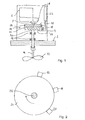
- Fig. 1 is a device on a wall 2 of a bulk container for determining a fill level of bulk material in the bulk material container with a housing 4 fastened to the wall 2, one in the housing 4 arranged drive device 6 with an output flange 8, one connected to the output flange 8 magnetic slip clutch 10 and one connected to the magnetic slip clutch 10 Rotary vane 12 attached to a drive shaft 14. On the magnetic Slip clutch 10 are arranged Hall sensors 16, 18 and 20 with a monitoring circuit 22 in the housing 4 are connected.
- the drive device 6, which is not on the housing 4 as a holder is rotatably attached, comprises an electric motor, not shown in the figures, by means of which the output flange 8 is rotatable.
- the magnetic slip clutch 10 comprises two parallel to each other in permanent magnetic disks 24 arranged at a predetermined distance and 26, of which the first permanent magnetic disc 24 has a clutch drive shaft 28 and the second permanent magnet disk 26 with a clutch output shaft 30 is connected.
- the clutch drive shaft 28, and thus the permanent magnet disc 24, is held on the output flange 8 of the drive device 6 and connected to it so that it can be driven by means of the drive device 6 is rotatable.
- Torques are between the permanent magnet disks 24 and 26, which are smaller than a trigger torque by the magnetic Forces between those in the surfaces of the permanent magnet disks 24 and 26 lying poles of the permanent magnet disks 24 and 26 are transferable.
- the trigger torque therefore depends on the strength of the permanent magnet disks 24 and 26 and their distance from each other. This distance between the permanent magnet disks 24 and 26 is adjustable so that the trigger torque of the magnetic slip clutch 10 is adjustable to a predetermined value.
- the clutch output shaft 28 is held in two bearings 32 and occurs through corresponding openings in the housing 4 and the wall 2 in the interior of the bulk container.
- Rotary wing 12 attached to the drive shaft 14.
- the rotary wing 12 has two laterally projecting surfaces, the normals of which are orthogonal to the Axis of the shaft 14 are aligned and is thus formed with two arms.
- the size of the surfaces of the rotary wing 12 is selected such that at Immersion of the rotary wing 12 in a bed of a predetermined Bulk material a significant inhibition of a rotary movement of the rotary wing 12 occurs around the drive shaft 14.
- the torque of the drive device 6 on its output flange 8 is greater than the trigger torque of the magnetic slip clutch 10 selected, which in turn depending on the properties of the Bulk and the shape and size of the surfaces of the rotary wing 12 so it is determined that a movement of the rotary wing 12 on or in a Bulk bulk material with the triggering torque is not possible.
- the rotary wing 12 is through the motor 6 via the magnetic Slipping clutch 10 rotates freely when the rotary wing 12 is not in contact with a bulk material.
- the triggering torque of the magnetic slip clutch 10 exceeded, so that the rotary wing 12 with the drive shaft 14 and the permanent magnet disk 26 on the clutch output shaft 30 no longer rotates.
- the Hall sensors 16 and 18 are in the edge region of the permanent magnet disk 26 arranged and serve as rotary vane rotation sensors for detection a rotational movement and a direction of rotation of the permanent magnet disc 26 and thus the associated clutch output shaft 30 or of the rotary wing 12. They each give rotary wing turn signals that on the strength or polarity of the magnetic field from the permanent magnet disc 26 is generated, depend and thus their rotational movement and direction.
- the Hall sensor arranged in the edge region of the permanent magnet disk 24 20 serves as an output element rotation sensor for determining a Rotational movement of the permanent magnet disk 24 or the associated Clutch drive shaft 28 or the output flange. He gives Output element rotation signals from the strength or polarity of the magnetic Field generated by the permanent magnet disks 24 depend and thus reproduce their rotational movement.
- the Hall sensors 16, 18 and 20 Viewed in the plane of the permanent magnet disks 24 and 26 (cf. Fig. 2) are the Hall sensors 16, 18 and 20 on the circumference of the permanent magnet disks 24 or 26 each in a predetermined, from the pole distribution of the magnet dependent angular distance, in the example of about 60 °, arranged from each other, in one in Fig. 2 by an arrow indicated direction of rotation of the drive device 6 or the output flange 8 Hall sensor 16 is the leading sensor.
- the Hall sensors 16 18 and 20 are used to process the rotary signals they emit 16, 18 and 20 connected to the monitoring circuit 22.
- the digital rotary signals emitted by the Hall sensors 16, 18 and 20 are recorded in the monitoring circuit 22 and processed further, for this purpose a processor and not shown in the figures has a memory device connected to the processor, in which including an evaluation program for processing the digital Rotary signals is stored.
- the digital rotary signals from the Hall sensors 16, 18 and 20 are designated S16, S18 and S20 in FIGS. 3 to 5 shown for different operating states of the device.
- Fig. 3 shows schematically the digital rotary signals of the Hall sensors 16, 18 and 20 in the form of voltages U 16 , U 18 and U 20 as a function of time t in the event that the rotary movement of the rotary wing 12 is not inhibited and this is therefore rotates synchronously with the output flange 8 or the clutch drive shaft 28.
- the Hall sensor 16 is arranged in front of the Hall sensor 18 in the direction of rotation of the output flange 8 of the drive device 6 (see FIG. 2), so that the signal S16 leads the signal S18.
- FIG. 4 shows the digital rotation signals in the same representation as in FIG. 3 for an operating state in which a movement of the rotary wing 12 by bulk material at a position corresponding to the rotary wing 12 Level is inhibited. Since with the rotary wing 12 also the clutch output shaft 30 and therefore not the permanent magnet disk 26 no longer rotate, no poles of the permanent magnet disk 26 move more past the Hall sensors 16 and 18 so that they, as in FIG. 3 shown schematically, give a constant rotation signal. Because the trigger torque the magnetic slip clutch 10 has been exceeded, the output flange 8 of the drive device 6 rotates together with the clutch drive shaft 28 and the permanent magnet disk 24 with constant speed, so that the digitized rotary signal S20 of the Hall sensor 20 remains essentially unchanged.
- the digital rotary signals S16, S18 and S20 are used to determine a Level and output of a corresponding signal in the corresponding trained monitoring circuit 22 processed.
- the monitoring circuit 22 When the device is operating, the monitoring circuit 22 basically checked whether the rotation angle signal S20 a predetermined maximum period corresponding to a minimum rotation speed of the Has drive device 6. If this is not the case, an error signal is generated output, which indicates a fault and triggers an alarm signal.
- the result is a very simple and reliable method to determine the fill level of bulk goods in a bulk goods container, that can be carried out by means of a simple device.
- a contactless slip clutch and Contactless rotating sensors work essentially wear-free and reliable.
Landscapes
- Physics & Mathematics (AREA)
- Thermal Sciences (AREA)
- Fluid Mechanics (AREA)
- General Physics & Mathematics (AREA)
- Measurement Of Levels Of Liquids Or Fluent Solid Materials (AREA)
- Filling Or Emptying Of Bunkers, Hoppers, And Tanks (AREA)
- Level Indicators Using A Float (AREA)
- Containers And Packaging Bodies Having A Special Means To Remove Contents (AREA)
- Control Of Motors That Do Not Use Commutators (AREA)
- Rotational Drive Of Disk (AREA)
Applications Claiming Priority (2)
| Application Number | Priority Date | Filing Date | Title |
|---|---|---|---|
| DE10217837 | 2002-04-22 | ||
| DE10217837A DE10217837A1 (de) | 2002-04-22 | 2002-04-22 | Verfahren und Vorrichtung zur Ermittlung eines Füllstands in einem Schüttgutbehälter |
Publications (3)
| Publication Number | Publication Date |
|---|---|
| EP1357366A2 true EP1357366A2 (fr) | 2003-10-29 |
| EP1357366A3 EP1357366A3 (fr) | 2004-03-31 |
| EP1357366B1 EP1357366B1 (fr) | 2006-06-07 |
Family
ID=28685219
Family Applications (1)
| Application Number | Title | Priority Date | Filing Date |
|---|---|---|---|
| EP03006653A Expired - Lifetime EP1357366B1 (fr) | 2002-04-22 | 2003-03-25 | Détermination du niveau de remplissage avec un élément rotatif |
Country Status (3)
| Country | Link |
|---|---|
| EP (1) | EP1357366B1 (fr) |
| AT (1) | ATE329235T1 (fr) |
| DE (2) | DE10217837A1 (fr) |
Cited By (4)
| Publication number | Priority date | Publication date | Assignee | Title |
|---|---|---|---|---|
| EP2592638A1 (fr) * | 2011-11-14 | 2013-05-15 | ENDRESS + HAUSER WETZER GmbH + Co. KG | Interrupteur de fin de course pour ailette rotative et procédé de fonctionnement de celui-ci |
| CN110371712A (zh) * | 2019-07-16 | 2019-10-25 | 咸宁南玻玻璃有限公司 | 一种阻旋式料位开关 |
| DE102019115122A1 (de) * | 2019-06-05 | 2020-12-10 | Kraussmaffei Technologies Gmbh | Verfahren zum Überwachen eines Füllstandes einer Zuführvorrichtung sowie Vorrichtung zum Durchführen des Verfahrens und Spritzgießmaschine/Extrudereinheit aufweisend eine solche Vorrichtung |
| CN118758395A (zh) * | 2024-06-12 | 2024-10-11 | 中联重科股份有限公司 | 料位检测方法和检测装置、泵送设备 |
Families Citing this family (3)
| Publication number | Priority date | Publication date | Assignee | Title |
|---|---|---|---|---|
| DE102009045768A1 (de) | 2009-10-16 | 2011-04-21 | Endress + Hauser Wetzer Gmbh + Co. Kg | Vorrichtung zur Bestimmung und/oder Überwachung eines vorbestimmten Füllstands eines Schüttguts |
| DE102011084561A1 (de) * | 2011-10-14 | 2013-04-18 | Endress + Hauser Wetzer Gmbh + Co Kg | Drehflügelgrenzschalter und Verfahren zum Betreiben eines Drehflügelgrenzschalters |
| DE102013103899B3 (de) * | 2013-04-18 | 2014-07-24 | MBA Instruments GmbH | Füllstandsanzeiger mit rotierendem Element |
Family Cites Families (3)
| Publication number | Priority date | Publication date | Assignee | Title |
|---|---|---|---|---|
| DE876167C (de) * | 1944-01-14 | 1953-05-11 | Peters Ag Claudius | Bunkerstandanzeiger |
| US2647251A (en) * | 1949-12-21 | 1953-07-28 | Distillers Co Yeast Ltd | Level indicator |
| DE3321815A1 (de) * | 1983-06-16 | 1984-12-20 | Heinrich 6931 Zwingenberg Kübler | Fuehler fuer schwerfaellig fliessende gueter |
-
2002
- 2002-04-22 DE DE10217837A patent/DE10217837A1/de not_active Withdrawn
-
2003
- 2003-03-25 AT AT03006653T patent/ATE329235T1/de not_active IP Right Cessation
- 2003-03-25 EP EP03006653A patent/EP1357366B1/fr not_active Expired - Lifetime
- 2003-03-25 DE DE50303640T patent/DE50303640D1/de not_active Expired - Lifetime
Cited By (6)
| Publication number | Priority date | Publication date | Assignee | Title |
|---|---|---|---|---|
| EP2592638A1 (fr) * | 2011-11-14 | 2013-05-15 | ENDRESS + HAUSER WETZER GmbH + Co. KG | Interrupteur de fin de course pour ailette rotative et procédé de fonctionnement de celui-ci |
| DE102019115122A1 (de) * | 2019-06-05 | 2020-12-10 | Kraussmaffei Technologies Gmbh | Verfahren zum Überwachen eines Füllstandes einer Zuführvorrichtung sowie Vorrichtung zum Durchführen des Verfahrens und Spritzgießmaschine/Extrudereinheit aufweisend eine solche Vorrichtung |
| WO2020244848A1 (fr) | 2019-06-05 | 2020-12-10 | Kraussmaffei Technologies Gmbh | Procédé de surveillance du niveau de remplissage d'un dispositif d'amenée et dispositif pour mettre en oeuvre ce procédé et machine de moulage par injection/unité d'extrusion présentant un tel dispositif |
| CN110371712A (zh) * | 2019-07-16 | 2019-10-25 | 咸宁南玻玻璃有限公司 | 一种阻旋式料位开关 |
| CN110371712B (zh) * | 2019-07-16 | 2024-03-08 | 咸宁南玻玻璃有限公司 | 一种阻旋式料位开关 |
| CN118758395A (zh) * | 2024-06-12 | 2024-10-11 | 中联重科股份有限公司 | 料位检测方法和检测装置、泵送设备 |
Also Published As
| Publication number | Publication date |
|---|---|
| DE50303640D1 (de) | 2006-07-20 |
| EP1357366B1 (fr) | 2006-06-07 |
| EP1357366A3 (fr) | 2004-03-31 |
| ATE329235T1 (de) | 2006-06-15 |
| DE10217837A1 (de) | 2003-11-06 |
Similar Documents
| Publication | Publication Date | Title |
|---|---|---|
| EP1408305B1 (fr) | Dispositif de mesure de l'angle absolu d'un arbre tournant | |
| EP1250534B1 (fr) | Organe d'entrainement d'une soupape de regulation comportant une unite pour detecter la position de la soupape | |
| EP2159547A2 (fr) | Bloc de capteurs pour un encodeur et encodeur pourvu d'un tel bloc de capteurs | |
| DE102004019945A1 (de) | Rotationsantriebsgerät | |
| EP2653428A1 (fr) | Capteur de longueur de câble | |
| DE102009060855B4 (de) | Elektromechanisches Füllstandmessgerät und ein Verfahren zur Füllstandmessung nach dem Prinzip der Verdrängungsmessung | |
| EP1129268B1 (fr) | Dispositif permettant de detecter le reglage de dispositifs de reglage a deplacement translatoire dans des vehicules | |
| EP1357366B1 (fr) | Détermination du niveau de remplissage avec un élément rotatif | |
| EP1902995B1 (fr) | Actionnement de porte pour une porte automatique | |
| DE19730196C2 (de) | Verfahren und Vorrichtung zur Füllstandsmessung nach dem Senklotprinzip | |
| EP1471337B1 (fr) | Dispositif de mesure du niveau d'un liquide dans un contenant | |
| EP1312534B1 (fr) | Dispositif pour la détermination de l'angle de braquage d'un volant | |
| EP1324002B1 (fr) | Dispositif pour mesurer la longueur actuelle d'un actionneur linéaire éléctromécanique | |
| EP2469239B1 (fr) | Dispositif de mesure d'angle multi-tours | |
| DE102007055098B4 (de) | Erfassungsanordnung | |
| EP1116954B1 (fr) | Compteur de rotations électroniques | |
| DE3321815A1 (de) | Fuehler fuer schwerfaellig fliessende gueter | |
| DE102013106395A1 (de) | Wegmesssystem und Wegmessverfahren | |
| EP1956346B1 (fr) | Dispositif de commande à l'arrêt d'un dispositif d'entraînement motorisé | |
| EP2857853B1 (fr) | Dispositif et procédé de vérification d'un processus de commutation d'un commutateur électrique | |
| EP1632764B1 (fr) | Dispositif et méthode de détermination d'un couple | |
| DE102012003254A1 (de) | Elektrische Lenkverriegelung | |
| EP2592638A1 (fr) | Interrupteur de fin de course pour ailette rotative et procédé de fonctionnement de celui-ci | |
| DE102009015781A1 (de) | Messvorrichtung mit Zeigerrückstellung | |
| DE102023124563A1 (de) | Aktor mit einem Sensorsystem zu Drehwinkelerfassung einer Welle |
Legal Events
| Date | Code | Title | Description |
|---|---|---|---|
| PUAI | Public reference made under article 153(3) epc to a published international application that has entered the european phase |
Free format text: ORIGINAL CODE: 0009012 |
|
| AK | Designated contracting states |
Kind code of ref document: A2 Designated state(s): AT BE BG CH CY CZ DE DK EE ES FI FR GB GR HU IE IT LI LU MC NL PT RO SE SI SK TR |
|
| AX | Request for extension of the european patent |
Extension state: AL LT LV MK RO |
|
| PUAL | Search report despatched |
Free format text: ORIGINAL CODE: 0009013 |
|
| AK | Designated contracting states |
Kind code of ref document: A3 Designated state(s): AT BE BG CH CY CZ DE DK EE ES FI FR GB GR HU IE IT LI LU MC NL PT RO SE SI SK TR |
|
| AX | Request for extension of the european patent |
Extension state: AL LT LV MK RO |
|
| AKX | Designation fees paid | ||
| 17P | Request for examination filed |
Effective date: 20040621 |
|
| RBV | Designated contracting states (corrected) |
Designated state(s): AT BE BG CH CY CZ DE DK EE ES FI FR GB GR HU IE IT LI LU MC NL PT RO SE SI SK TR |
|
| REG | Reference to a national code |
Ref country code: DE Ref legal event code: 8566 |
|
| 17Q | First examination report despatched |
Effective date: 20050428 |
|
| GRAP | Despatch of communication of intention to grant a patent |
Free format text: ORIGINAL CODE: EPIDOSNIGR1 |
|
| GRAS | Grant fee paid |
Free format text: ORIGINAL CODE: EPIDOSNIGR3 |
|
| GRAA | (expected) grant |
Free format text: ORIGINAL CODE: 0009210 |
|
| AK | Designated contracting states |
Kind code of ref document: B1 Designated state(s): AT BE BG CH CY CZ DE DK EE ES FI FR GB GR HU IE IT LI LU MC NL PT RO SE SI SK TR |
|
| PG25 | Lapsed in a contracting state [announced via postgrant information from national office to epo] |
Ref country code: IT Free format text: LAPSE BECAUSE OF FAILURE TO SUBMIT A TRANSLATION OF THE DESCRIPTION OR TO PAY THE FEE WITHIN THE PRESCRIBED TIME-LIMIT;WARNING: LAPSES OF ITALIAN PATENTS WITH EFFECTIVE DATE BEFORE 2007 MAY HAVE OCCURRED AT ANY TIME BEFORE 2007. THE CORRECT EFFECTIVE DATE MAY BE DIFFERENT FROM THE ONE RECORDED. Effective date: 20060607 Ref country code: CZ Free format text: LAPSE BECAUSE OF FAILURE TO SUBMIT A TRANSLATION OF THE DESCRIPTION OR TO PAY THE FEE WITHIN THE PRESCRIBED TIME-LIMIT Effective date: 20060607 Ref country code: RO Free format text: LAPSE BECAUSE OF FAILURE TO SUBMIT A TRANSLATION OF THE DESCRIPTION OR TO PAY THE FEE WITHIN THE PRESCRIBED TIME-LIMIT Effective date: 20060607 Ref country code: SI Free format text: LAPSE BECAUSE OF FAILURE TO SUBMIT A TRANSLATION OF THE DESCRIPTION OR TO PAY THE FEE WITHIN THE PRESCRIBED TIME-LIMIT Effective date: 20060607 Ref country code: SK Free format text: LAPSE BECAUSE OF FAILURE TO SUBMIT A TRANSLATION OF THE DESCRIPTION OR TO PAY THE FEE WITHIN THE PRESCRIBED TIME-LIMIT Effective date: 20060607 Ref country code: IE Free format text: LAPSE BECAUSE OF FAILURE TO SUBMIT A TRANSLATION OF THE DESCRIPTION OR TO PAY THE FEE WITHIN THE PRESCRIBED TIME-LIMIT Effective date: 20060607 Ref country code: FI Free format text: LAPSE BECAUSE OF FAILURE TO SUBMIT A TRANSLATION OF THE DESCRIPTION OR TO PAY THE FEE WITHIN THE PRESCRIBED TIME-LIMIT Effective date: 20060607 Ref country code: NL Free format text: LAPSE BECAUSE OF FAILURE TO SUBMIT A TRANSLATION OF THE DESCRIPTION OR TO PAY THE FEE WITHIN THE PRESCRIBED TIME-LIMIT Effective date: 20060607 |
|
| REG | Reference to a national code |
Ref country code: GB Ref legal event code: FG4D Free format text: NOT ENGLISH |
|
| REG | Reference to a national code |
Ref country code: CH Ref legal event code: EP |
|
| REG | Reference to a national code |
Ref country code: IE Ref legal event code: FG4D Free format text: LANGUAGE OF EP DOCUMENT: GERMAN |
|
| REF | Corresponds to: |
Ref document number: 50303640 Country of ref document: DE Date of ref document: 20060720 Kind code of ref document: P |
|
| GBT | Gb: translation of ep patent filed (gb section 77(6)(a)/1977) |
Effective date: 20060814 |
|
| PG25 | Lapsed in a contracting state [announced via postgrant information from national office to epo] |
Ref country code: DK Free format text: LAPSE BECAUSE OF FAILURE TO SUBMIT A TRANSLATION OF THE DESCRIPTION OR TO PAY THE FEE WITHIN THE PRESCRIBED TIME-LIMIT Effective date: 20060907 Ref country code: SE Free format text: LAPSE BECAUSE OF FAILURE TO SUBMIT A TRANSLATION OF THE DESCRIPTION OR TO PAY THE FEE WITHIN THE PRESCRIBED TIME-LIMIT Effective date: 20060907 |
|
| PG25 | Lapsed in a contracting state [announced via postgrant information from national office to epo] |
Ref country code: ES Free format text: LAPSE BECAUSE OF FAILURE TO SUBMIT A TRANSLATION OF THE DESCRIPTION OR TO PAY THE FEE WITHIN THE PRESCRIBED TIME-LIMIT Effective date: 20060918 |
|
| PG25 | Lapsed in a contracting state [announced via postgrant information from national office to epo] |
Ref country code: PT Free format text: LAPSE BECAUSE OF FAILURE TO SUBMIT A TRANSLATION OF THE DESCRIPTION OR TO PAY THE FEE WITHIN THE PRESCRIBED TIME-LIMIT Effective date: 20061107 |
|
| NLV1 | Nl: lapsed or annulled due to failure to fulfill the requirements of art. 29p and 29m of the patents act | ||
| ET | Fr: translation filed | ||
| REG | Reference to a national code |
Ref country code: IE Ref legal event code: FD4D |
|
| PLBE | No opposition filed within time limit |
Free format text: ORIGINAL CODE: 0009261 |
|
| STAA | Information on the status of an ep patent application or granted ep patent |
Free format text: STATUS: NO OPPOSITION FILED WITHIN TIME LIMIT |
|
| 26N | No opposition filed |
Effective date: 20070308 |
|
| REG | Reference to a national code |
Ref country code: CH Ref legal event code: PL |
|
| BERE | Be: lapsed |
Owner name: MAIHAK A.G. Effective date: 20070331 |
|
| PG25 | Lapsed in a contracting state [announced via postgrant information from national office to epo] |
Ref country code: BE Free format text: LAPSE BECAUSE OF NON-PAYMENT OF DUE FEES Effective date: 20070331 |
|
| PG25 | Lapsed in a contracting state [announced via postgrant information from national office to epo] |
Ref country code: MC Free format text: LAPSE BECAUSE OF NON-PAYMENT OF DUE FEES Effective date: 20070331 |
|
| PG25 | Lapsed in a contracting state [announced via postgrant information from national office to epo] |
Ref country code: LI Free format text: LAPSE BECAUSE OF NON-PAYMENT OF DUE FEES Effective date: 20070331 Ref country code: CH Free format text: LAPSE BECAUSE OF NON-PAYMENT OF DUE FEES Effective date: 20070331 |
|
| PG25 | Lapsed in a contracting state [announced via postgrant information from national office to epo] |
Ref country code: GR Free format text: LAPSE BECAUSE OF FAILURE TO SUBMIT A TRANSLATION OF THE DESCRIPTION OR TO PAY THE FEE WITHIN THE PRESCRIBED TIME-LIMIT Effective date: 20060908 |
|
| PG25 | Lapsed in a contracting state [announced via postgrant information from national office to epo] |
Ref country code: BG Free format text: LAPSE BECAUSE OF FAILURE TO SUBMIT A TRANSLATION OF THE DESCRIPTION OR TO PAY THE FEE WITHIN THE PRESCRIBED TIME-LIMIT Effective date: 20060907 Ref country code: AT Free format text: LAPSE BECAUSE OF NON-PAYMENT OF DUE FEES Effective date: 20070325 |
|
| PG25 | Lapsed in a contracting state [announced via postgrant information from national office to epo] |
Ref country code: EE Free format text: LAPSE BECAUSE OF FAILURE TO SUBMIT A TRANSLATION OF THE DESCRIPTION OR TO PAY THE FEE WITHIN THE PRESCRIBED TIME-LIMIT Effective date: 20060607 |
|
| REG | Reference to a national code |
Ref country code: GB Ref legal event code: 732E Free format text: REGISTERED BETWEEN 20090319 AND 20090325 |
|
| PG25 | Lapsed in a contracting state [announced via postgrant information from national office to epo] |
Ref country code: LU Free format text: LAPSE BECAUSE OF NON-PAYMENT OF DUE FEES Effective date: 20070325 Ref country code: CY Free format text: LAPSE BECAUSE OF FAILURE TO SUBMIT A TRANSLATION OF THE DESCRIPTION OR TO PAY THE FEE WITHIN THE PRESCRIBED TIME-LIMIT Effective date: 20060607 |
|
| PG25 | Lapsed in a contracting state [announced via postgrant information from national office to epo] |
Ref country code: HU Free format text: LAPSE BECAUSE OF FAILURE TO SUBMIT A TRANSLATION OF THE DESCRIPTION OR TO PAY THE FEE WITHIN THE PRESCRIBED TIME-LIMIT Effective date: 20061208 Ref country code: TR Free format text: LAPSE BECAUSE OF FAILURE TO SUBMIT A TRANSLATION OF THE DESCRIPTION OR TO PAY THE FEE WITHIN THE PRESCRIBED TIME-LIMIT Effective date: 20060607 |
|
| REG | Reference to a national code |
Ref country code: FR Ref legal event code: TP |
|
| REG | Reference to a national code |
Ref country code: FR Ref legal event code: PLFP Year of fee payment: 14 |
|
| PGFP | Annual fee paid to national office [announced via postgrant information from national office to epo] |
Ref country code: GB Payment date: 20160322 Year of fee payment: 14 Ref country code: FR Payment date: 20160322 Year of fee payment: 14 |
|
| PGFP | Annual fee paid to national office [announced via postgrant information from national office to epo] |
Ref country code: DE Payment date: 20160525 Year of fee payment: 14 |
|
| PGFP | Annual fee paid to national office [announced via postgrant information from national office to epo] |
Ref country code: IT Payment date: 20160318 Year of fee payment: 14 |
|
| REG | Reference to a national code |
Ref country code: DE Ref legal event code: R119 Ref document number: 50303640 Country of ref document: DE |
|
| GBPC | Gb: european patent ceased through non-payment of renewal fee |
Effective date: 20170325 |
|
| REG | Reference to a national code |
Ref country code: FR Ref legal event code: ST Effective date: 20171130 |
|
| PG25 | Lapsed in a contracting state [announced via postgrant information from national office to epo] |
Ref country code: DE Free format text: LAPSE BECAUSE OF NON-PAYMENT OF DUE FEES Effective date: 20171003 Ref country code: FR Free format text: LAPSE BECAUSE OF NON-PAYMENT OF DUE FEES Effective date: 20170331 |
|
| PG25 | Lapsed in a contracting state [announced via postgrant information from national office to epo] |
Ref country code: GB Free format text: LAPSE BECAUSE OF NON-PAYMENT OF DUE FEES Effective date: 20170325 Ref country code: IT Free format text: LAPSE BECAUSE OF NON-PAYMENT OF DUE FEES Effective date: 20170325 |