EP1357417A2 - Oculaire pour visualiser une image plate - Google Patents
Oculaire pour visualiser une image plate Download PDFInfo
- Publication number
- EP1357417A2 EP1357417A2 EP03252325A EP03252325A EP1357417A2 EP 1357417 A2 EP1357417 A2 EP 1357417A2 EP 03252325 A EP03252325 A EP 03252325A EP 03252325 A EP03252325 A EP 03252325A EP 1357417 A2 EP1357417 A2 EP 1357417A2
- Authority
- EP
- European Patent Office
- Prior art keywords
- eyepiece
- reflecting
- viewing
- refracting
- index
- Prior art date
- Legal status (The legal status is an assumption and is not a legal conclusion. Google has not performed a legal analysis and makes no representation as to the accuracy of the status listed.)
- Withdrawn
Links
- 230000003287 optical effect Effects 0.000 claims abstract description 23
- 230000004075 alteration Effects 0.000 claims abstract description 13
- 239000006185 dispersion Substances 0.000 claims description 10
- 239000011521 glass Substances 0.000 claims description 10
- 239000000853 adhesive Substances 0.000 claims description 2
- 230000001070 adhesive effect Effects 0.000 claims description 2
- 210000001747 pupil Anatomy 0.000 description 13
- 210000003128 head Anatomy 0.000 description 6
- 235000012771 pancakes Nutrition 0.000 description 4
- 239000000463 material Substances 0.000 description 3
- 239000007787 solid Substances 0.000 description 3
- 201000009310 astigmatism Diseases 0.000 description 2
- 230000007704 transition Effects 0.000 description 2
- OKTJSMMVPCPJKN-UHFFFAOYSA-N Carbon Chemical compound [C] OKTJSMMVPCPJKN-UHFFFAOYSA-N 0.000 description 1
- 206010020675 Hypermetropia Diseases 0.000 description 1
- 230000001133 acceleration Effects 0.000 description 1
- 230000005540 biological transmission Effects 0.000 description 1
- 239000002041 carbon nanotube Substances 0.000 description 1
- 229910021393 carbon nanotube Inorganic materials 0.000 description 1
- 238000005094 computer simulation Methods 0.000 description 1
- 230000004424 eye movement Effects 0.000 description 1
- 201000006318 hyperopia Diseases 0.000 description 1
- 230000004305 hyperopia Effects 0.000 description 1
- 239000011159 matrix material Substances 0.000 description 1
- 238000000034 method Methods 0.000 description 1
- 238000012986 modification Methods 0.000 description 1
- 230000004048 modification Effects 0.000 description 1
- 208000001491 myopia Diseases 0.000 description 1
- 230000004379 myopia Effects 0.000 description 1
- 238000001228 spectrum Methods 0.000 description 1
- 238000001429 visible spectrum Methods 0.000 description 1
- 230000000007 visual effect Effects 0.000 description 1
Images

Classifications
-
- G—PHYSICS
- G02—OPTICS
- G02B—OPTICAL ELEMENTS, SYSTEMS OR APPARATUS
- G02B27/00—Optical systems or apparatus not provided for by any of the groups G02B1/00 - G02B26/00, G02B30/00
- G02B27/01—Head-up displays
- G02B27/017—Head mounted
- G02B27/0172—Head mounted characterised by optical features
-
- G—PHYSICS
- G02—OPTICS
- G02B—OPTICAL ELEMENTS, SYSTEMS OR APPARATUS
- G02B25/00—Eyepieces; Magnifying glasses
- G02B25/001—Eyepieces
-
- G—PHYSICS
- G02—OPTICS
- G02B—OPTICAL ELEMENTS, SYSTEMS OR APPARATUS
- G02B27/00—Optical systems or apparatus not provided for by any of the groups G02B1/00 - G02B26/00, G02B30/00
- G02B27/01—Head-up displays
- G02B27/0101—Head-up displays characterised by optical features
- G02B2027/0123—Head-up displays characterised by optical features comprising devices increasing the field of view
-
- G—PHYSICS
- G02—OPTICS
- G02B—OPTICAL ELEMENTS, SYSTEMS OR APPARATUS
- G02B5/00—Optical elements other than lenses
- G02B5/30—Polarising elements
Definitions
- This invention relates to an eyepiece for viewing a flat image.
- the flat image may form part of a flat panel display such for example as a rear projection screen, an electronic micro display, or a real aerial image formed by another optical system.
- Eyepieces are known which include an optical arrangement known as a pancake window. These known eyepieces are used to view flat panel displays but they only have a limited field of view.
- any eyepiece there is a zone in space where the eye pupil can be placed in order to view the image.
- the zone is defined by the distance between the last face of the last optical element, called the eye-relief, and an area at this distance where the image can be seen. If the eye pupil is moved laterally outside this area, some optical systems exhibit an exit pupil where a sudden transition from image to darkness would be observed. Other systems have a less clear transition where, as the eye is moved outside the design viewing area, the image is observed to lose brightness and/or resolution.
- the head mounted display When an eyepiece is used in a head mounted display, the head mounted display forms a means for interacting with a three dimensional virtual environment.
- head tracking devices are used to monitor the position and orientation of the user's head, information from which is fed back to an image generator such that the image displayed corresponds to the position and the orientation within a computer model.
- Head mounted displays with a large field of view give the impression of being in the image, as opposed to watching on a screen.
- Optical solutions for the eyepiece tend to trade the desired field of view for viewing area size.
- the eye relief can only be scaled up by increasing the size and therefore the weight of the eyepiece.
- refractive eyepieces are complicated, requiring many large and heavy elements, positioned in some cases well in front of the eye, which mitigates against an ideal weight distribution.
- the desired total field of view for a head mounted display is 120° x 67°.
- Known head mounted displays that have been designed to have a large field of view have been both very heavy and very expensive.
- the head mounted displays are usually unbalanced, with most of the weight being to the front of the user's head.
- the excessive weight of the known head mounted displays has made them uncomfortable to use and inefficient. This is because, in order to work effectively, the eyepiece must be in a fixed location relative to the user.
- the excessive weight of the head mounted display means that inertia is substantial and tends to cause the head mounted display to lag when the user's head makes an angular acceleration, and to overshoot as the user's head decelerates.
- an eyepiece for viewing a flat image which eyepiece has a wide field of view and which eyepiece comprises a cemented doublet of reflecting and refracting optical components, the reflecting and refracting optical components being such that they are each of a different refractive index whereby chromatic aberrations and spherical aberrations are reduced.
- the eyepiece of the present invention may be compact and lightweight.
- the eyepiece may have a wide field of view for observing flat panel displays which can be in the form of a rear projection screen, an electronic micro display, or a real aerial image formed by another optical system.
- the eyepiece of the present invention may afford a viewing area at the desired eye relief that is greater than the maximum eye pupil of 8mm, allowing the pupil to swivel whilst staying within the viewing area.
- the eyepiece may be one in which the cemented doublet comprises six of the reflecting and refracting optical components cemented together by an optical adhesive.
- the six reflecting and refracting components of the cemented doublet may comprise a semi-reflecting mirror surface for providing the majority of the focusing power of the eyepiece, two refracting surfaces for providing the remainder of the focusing power of the eyepiece, two quarter wave retarders and a polarising mirror, the two quarter wave retarders and the polarising mirror being such as to control the light path through the cemented doublet.
- the eyepiece may include a seventh optical component in the form of a single planoconvex lens.
- the two refracting surfaces may be two convex refracting surfaces.
- the eyepiece may be one in which a low-index low-dispersion lens is positioned on one side of the semi-reflecting mirror surface, and in which a high-index high-dispersion lens is positioned on the other side of the semi-reflecting mirror surface.
- the low-index low-dispersion lens is preferably made of glass
- the high-index high-dispersion lens is preferably made of glass.
- the present invention also provides viewing apparatus comprising the eyepiece of the invention.
- the viewing apparatus may be for viewing a flat panel display.
- the viewing apparatus may form part of a head mounted display.
- the viewing apparatus may have one of the eyepieces for each eye.
- the viewing apparatus may be used to view a rear projection screen, an electronic micro display, a micro-emissive display panel, or real aerial image formed by another optical system.
- the micro-emissive display panel may be an organic light emitting diode display panel, an active matrix electroluminescent display panel, a field emission display panel, a carbon nanotube display panel, a vacuum fluorescent display panel, or any other desired and appropriate type of micro-emissive display panel.
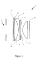
- an eyepiece 2 which is based on a known pancake window.
- the eyepiece 2 may be regarded as a straight-through on-axis mirror collimator which uses polarisation to suppress transmission orders that are not desired.
- the display source was a spherical screen, the reflected image of which was rotationally symmetrical about the eye.
- the maximum field of view for this known arrangement was approximately 88°, limited by the interference of the screen with the surface of the spherical beam splitter. It is known that if the pancake window is made from solid glass, then the field of view can be increased. It is also desirable to use a flat panel as the display source.
- Known eyepieces when used with a flat panel as the display source have only had limited field of view per channel.
- Figure 2 shows the relationship of the eye relief 26 to the exit pupil 28, the viewing area 24 and the field of view 30. It can be seen that as the eye relief 26 increases, the exit pupil 28 must increase in order to maintain the field of view 30. Therefore as the eye relief increases, the size and therefore the weight of the eyepiece must increase.
- the eyepiece 2 of the present invention needs to be of a design that enables it to be placed close to the eye, closer than the minimum eye relief to facilitate the wearing of spectacles which is approximately 25mm.
- the field of view of the eyepiece can be represented by a truncated cone, the area of the truncated end representing the desired viewing area.
- the exit pupil of the optics must fit across the wide end of the cone at the desired eye relief.
- the eyepiece must be scaled in all three dimensions. Therefore any additional eye relief will increase the weight of the eyepiece. This increase in weight of the eyepiece is proportional to the cube of the eye relief.
- a catadioptric design incorporating chromatic correction is used.
- the eyepiece 2 is therefore designed for use without spectacles.
- the eye relief is less than 25mm, enabling the weight to be reduced.
- the eyepiece 2 is however adjustable through + 4 or -4 diopters, catering for users with both myopia and hypermetropia. The user is however still able to use contact lenses.
- the eyepiece 2 comprises seven components, six of which are cemented together in a preferred embodiment in order to form a solid optical assembly, plus a single planoconvex lens.
- the eyepiece 2 comprises a semi-reflecting mirror surface 4, refracting surfaces 6, 8, quarter wave retarders 10, 12 and a polarising mirror 14.
- the semi-reflecting mirror surface 4 With the observer's eye positioned at a viewing area 16, the semi-reflecting mirror surface 4 provides most of the focusing power of the eyepiece 2. The remainder of the focusing power of the eyepiece 2 comes from the refracting surfaces 6, 8.
- the light path through the eyepiece 2 is made to follow the desired path by the action of the quarter wave retarders 10, 12 and the polarising mirror 14.
- the quarter wave retarders 10, 12 have close to the same retardation across the visible spectrum.
- the polarising mirror 14 could also be made with a combination of a beamsplitter and a polarising filter.
- the field of view is further increased by making the eyepiece 2 from solid glass.
- This introduces significant chromatic aberration, approximately 14 arc minutes, over the visual spectrum.
- the chromatic aberrations can be reduced by about 50% which is much more acceptable to the observer.
- Different glass materials on either side of semi-reflecting surface take the form of an achromatic doublet where a lens 18 is a low index low dispersion glass lens, whilst a lens 20 is a high index high dispersion glass lens.
- the residual spherical aberration is equivalent to an image blur, which is less than the threshold acuity (1.3 arc minutes) of a 3mm diameter eye pupil.
- the image blur is equivalent to 8 or 10 arc minutes, which is similar to the acuity of the average eye with a 7mm pupil diameter.
- the eyepiece shown in Figure 1 gives a performance which is compatible to the threshold acuity of the average eye over an interocular range of 53 - 75mm.
- the positive power semi-reflecting mirror surface 4 over-corrects the field curvature of the eyepiece 2 to such an extent that the image surface or screen 22 would be significantly convex towards the observer.
- the two convex refracting surfaces 6, 8 are used to counteract the over-correction of the field curvature such that a flat screen can be comfortable to view. Also, the two convex refracting surfaces 6, 8 give additional positive focusing power to the eyepiece 2, and provide some astigmatism correction.
Landscapes
- Physics & Mathematics (AREA)
- General Physics & Mathematics (AREA)
- Optics & Photonics (AREA)
- Lenses (AREA)
Applications Claiming Priority (2)
| Application Number | Priority Date | Filing Date | Title |
|---|---|---|---|
| GB0209362A GB2387920B (en) | 2002-04-24 | 2002-04-24 | An eyepiece for viewing a flat image and comprising a cemented doublet of reflecting and refracting optical components |
| GB0209362 | 2002-04-24 |
Publications (2)
| Publication Number | Publication Date |
|---|---|
| EP1357417A2 true EP1357417A2 (fr) | 2003-10-29 |
| EP1357417A3 EP1357417A3 (fr) | 2005-02-02 |
Family
ID=9935410
Family Applications (1)
| Application Number | Title | Priority Date | Filing Date |
|---|---|---|---|
| EP03252325A Withdrawn EP1357417A3 (fr) | 2002-04-24 | 2003-04-11 | Oculaire pour visualiser une image plate |
Country Status (3)
| Country | Link |
|---|---|
| US (1) | US6873471B2 (fr) |
| EP (1) | EP1357417A3 (fr) |
| GB (1) | GB2387920B (fr) |
Cited By (4)
| Publication number | Priority date | Publication date | Assignee | Title |
|---|---|---|---|---|
| WO2006125028A3 (fr) * | 2005-05-16 | 2007-01-04 | Edward Ho | Appareil et procede de collecte d'energie |
| EP3118666A1 (fr) * | 2015-07-13 | 2017-01-18 | Shenzhen Dlodlo Technologies Co., Ltd. | Module d'amplification optique à courte distance et module optique d'affichage proche de l'oeil utilisant celui-ci |
| EP3410176A4 (fr) * | 2016-01-28 | 2019-09-18 | Shenzhen Dlodlo New Technology Co., Ltd. | Module amplificateur optique à courte distance, procédé d'amplification et système d'amplification |
| EP3547005A1 (fr) * | 2018-03-25 | 2019-10-02 | INTEL Corporation | Technologies pour visiocasque efficace avec lentilles pancake |
Families Citing this family (20)
| Publication number | Priority date | Publication date | Assignee | Title |
|---|---|---|---|---|
| US8781794B2 (en) | 2010-10-21 | 2014-07-15 | Lockheed Martin Corporation | Methods and systems for creating free space reflective optical surfaces |
| US10359545B2 (en) | 2010-10-21 | 2019-07-23 | Lockheed Martin Corporation | Fresnel lens with reduced draft facet visibility |
| US9632315B2 (en) | 2010-10-21 | 2017-04-25 | Lockheed Martin Corporation | Head-mounted display apparatus employing one or more fresnel lenses |
| US8625200B2 (en) | 2010-10-21 | 2014-01-07 | Lockheed Martin Corporation | Head-mounted display apparatus employing one or more reflective optical surfaces |
| JP6246592B2 (ja) | 2010-12-16 | 2017-12-13 | ロッキード マーティン コーポレーション | 画素レンズを有するコリメーティングディスプレイ |
| US9086569B1 (en) * | 2014-02-05 | 2015-07-21 | Google Inc. | Head mounted display with color correcting doublet eyepiece |
| US10684476B2 (en) | 2014-10-17 | 2020-06-16 | Lockheed Martin Corporation | Head-wearable ultra-wide field of view display device |
| KR102295452B1 (ko) * | 2014-10-24 | 2021-08-27 | 이매진 코퍼레이션 | 마이크로디스플레이 기반 몰입형 헤드셋 |
| US9939650B2 (en) | 2015-03-02 | 2018-04-10 | Lockheed Martin Corporation | Wearable display system |
| US9557568B1 (en) | 2015-09-03 | 2017-01-31 | 3M Innovative Properties Company | Head-mounted display |
| US10754156B2 (en) | 2015-10-20 | 2020-08-25 | Lockheed Martin Corporation | Multiple-eye, single-display, ultrawide-field-of-view optical see-through augmented reality system |
| EP3405828A1 (fr) | 2016-01-22 | 2018-11-28 | Corning Incorporated | Appareil d'affichage personnel à champ large |
| US9995936B1 (en) | 2016-04-29 | 2018-06-12 | Lockheed Martin Corporation | Augmented reality systems having a virtual image overlaying an infrared portion of a live scene |
| US10816795B2 (en) * | 2016-11-28 | 2020-10-27 | Amalgamated Vision, Llc | Wearable display for near-to-eye viewing |
| US10976551B2 (en) | 2017-08-30 | 2021-04-13 | Corning Incorporated | Wide field personal display device |
| JP6436221B2 (ja) * | 2017-12-18 | 2018-12-12 | セイコーエプソン株式会社 | 虚像表示装置 |
| US11340451B2 (en) | 2019-06-19 | 2022-05-24 | Amalgamated Vision, Llc | Wearable display for near-to-eye viewing with expanded beam |
| CN112596240B (zh) * | 2020-12-21 | 2022-09-20 | 歌尔光学科技有限公司 | 成像光路和头戴显示设备 |
| CN112596238B (zh) * | 2020-12-21 | 2022-09-20 | 歌尔光学科技有限公司 | 成像光路和头戴显示设备 |
| CN116755254A (zh) | 2023-06-28 | 2023-09-15 | 辰瑞光学(常州)股份有限公司 | 虚拟现实光学镜头 |
Family Cites Families (11)
| Publication number | Priority date | Publication date | Assignee | Title |
|---|---|---|---|---|
| GB228354A (en) * | 1924-02-15 | 1925-02-05 | Ronald John Bracey | Improvements in magnifying lenses |
| US5539578A (en) * | 1993-03-02 | 1996-07-23 | Olympus Optical Co., Ltd. | Image display apparatus |
| JPH07261088A (ja) * | 1994-03-18 | 1995-10-13 | Olympus Optical Co Ltd | 共心光学系 |
| US5734505A (en) * | 1994-05-27 | 1998-03-31 | Olympus Optical Co., Ltd. | Visual display apparatus |
| JPH08122642A (ja) * | 1994-10-26 | 1996-05-17 | Olympus Optical Co Ltd | 光学系 |
| JP3295583B2 (ja) * | 1994-12-19 | 2002-06-24 | シャープ株式会社 | 光学装置および該光学装置を用いた頭部搭載型ディスプレイ |
| JP3599828B2 (ja) * | 1995-05-18 | 2004-12-08 | オリンパス株式会社 | 光学装置 |
| JP3497607B2 (ja) * | 1995-05-26 | 2004-02-16 | オリンパス株式会社 | 接眼光学系及びそれを用いた画像表示装置 |
| JP3537230B2 (ja) * | 1995-08-21 | 2004-06-14 | オリンパス株式会社 | 接眼光学系及びそれを用いた画像表示装置 |
| US6075651A (en) * | 1999-01-28 | 2000-06-13 | Kaiser Electro-Optics, Inc. | Compact collimating apparatus |
| JP2003529795A (ja) * | 2000-03-31 | 2003-10-07 | コーニンクレッカ フィリップス エレクトロニクス エヌ ヴィ | ヘッドマウントディスプレイ |
-
2002
- 2002-04-24 GB GB0209362A patent/GB2387920B/en not_active Expired - Lifetime
-
2003
- 2003-04-11 EP EP03252325A patent/EP1357417A3/fr not_active Withdrawn
- 2003-04-16 US US10/417,387 patent/US6873471B2/en not_active Expired - Fee Related
Cited By (7)
| Publication number | Priority date | Publication date | Assignee | Title |
|---|---|---|---|---|
| US7558452B2 (en) | 2001-08-02 | 2009-07-07 | Edward Ho | Apparatus and method for collecting energy |
| WO2006125028A3 (fr) * | 2005-05-16 | 2007-01-04 | Edward Ho | Appareil et procede de collecte d'energie |
| EP3118666A1 (fr) * | 2015-07-13 | 2017-01-18 | Shenzhen Dlodlo Technologies Co., Ltd. | Module d'amplification optique à courte distance et module optique d'affichage proche de l'oeil utilisant celui-ci |
| EP3410176A4 (fr) * | 2016-01-28 | 2019-09-18 | Shenzhen Dlodlo New Technology Co., Ltd. | Module amplificateur optique à courte distance, procédé d'amplification et système d'amplification |
| US11604349B2 (en) | 2016-01-28 | 2023-03-14 | Shenzhen Dlodlo New Technology Co., Ltd. | Short-distance optical amplification module, amplification method and amplification system |
| EP3547005A1 (fr) * | 2018-03-25 | 2019-10-02 | INTEL Corporation | Technologies pour visiocasque efficace avec lentilles pancake |
| US10712569B2 (en) | 2018-03-25 | 2020-07-14 | Intel Corporation | Technologies for efficient head-mounted display with pancake lenses |
Also Published As
| Publication number | Publication date |
|---|---|
| GB2387920B (en) | 2005-11-23 |
| GB0209362D0 (en) | 2002-06-05 |
| EP1357417A3 (fr) | 2005-02-02 |
| GB2387920A (en) | 2003-10-29 |
| US20030202253A1 (en) | 2003-10-30 |
| US6873471B2 (en) | 2005-03-29 |
Similar Documents
| Publication | Publication Date | Title |
|---|---|---|
| US6873471B2 (en) | Eyepiece for viewing a flat image | |
| US7525735B2 (en) | High resolution head mounted projection display | |
| US5526183A (en) | Helmet visor display employing reflective, refractive and diffractive optical elements | |
| US5035474A (en) | Biocular holographic helmet mounted display | |
| JPH0339925A (ja) | デイスプレイ装置に使用のヘルメットへの取着装置 | |
| JP2554415Y2 (ja) | ホログラフィックヘルメットに装着した両眼用デイスプレイ | |
| IL244903A (en) | Interior Shield Alert Display | |
| WO1996005533A1 (fr) | Procede et appareil de projection directe sur la retine | |
| US20190049721A1 (en) | Virtual reality head mounted display | |
| WO1998028641A9 (fr) | Lunettes de vision nocturne panoramique | |
| WO1998028641A1 (fr) | Lunettes de vision nocturne panoramique | |
| JP2021536023A (ja) | 接眼レンズ光学システム及び頭部装着型ディスプレイ | |
| Huxford | Wide FOV head-mounted display using hybrid optics | |
| Rogers et al. | Biocular display optics | |
| WO2022175813A1 (fr) | Lentille optique fovéale pour affichage proche de l'œil | |
| Melzer et al. | Partial binocular-overlap in helmet-mounted displays | |
| CN117310998B (zh) | 光学系统及近眼显示设备 | |
| CN117130166B (zh) | 光学系统及近眼显示设备 | |
| EP3631568B1 (fr) | Oculaire pour affichage personnel et affichage personnel comprenant ledit oculaire | |
| US10520720B2 (en) | Large format biocular lens | |
| JP3597456B2 (ja) | 偏心光学系及びそれを用いた視覚表示装置 | |
| CN117148590B (zh) | 光学系统及近眼显示设备 | |
| US12210160B2 (en) | System to superimpose information over a users field of view | |
| Rolland et al. | Displays: head-mounted | |
| Tsou et al. | Visual factors associated with head-mounted displays |
Legal Events
| Date | Code | Title | Description |
|---|---|---|---|
| PUAI | Public reference made under article 153(3) epc to a published international application that has entered the european phase |
Free format text: ORIGINAL CODE: 0009012 |
|
| AK | Designated contracting states |
Kind code of ref document: A2 Designated state(s): AT BE BG CH CY CZ DE DK EE ES FI FR GB GR HU IE IT LI LU MC NL PT RO SE SI SK TR |
|
| AX | Request for extension of the european patent |
Extension state: AL LT LV MK |
|
| PUAL | Search report despatched |
Free format text: ORIGINAL CODE: 0009013 |
|
| AK | Designated contracting states |
Kind code of ref document: A3 Designated state(s): AT BE BG CH CY CZ DE DK EE ES FI FR GB GR HU IE IT LI LU MC NL PT RO SE SI SK TR |
|
| AX | Request for extension of the european patent |
Extension state: AL LT LV MK |
|
| AKX | Designation fees paid |
Designated state(s): AT BE BG CH CY CZ DE DK EE ES FI FR GB GR HU IE IT LI LU MC NL PT RO SE SI SK TR |
|
| STAA | Information on the status of an ep patent application or granted ep patent |
Free format text: STATUS: THE APPLICATION IS DEEMED TO BE WITHDRAWN |
|
| 18D | Application deemed to be withdrawn |
Effective date: 20050803 |