EP1357782B1 - Machine roulante pour le travail du sol, en particulier tondeuse a gazon - Google Patents
Machine roulante pour le travail du sol, en particulier tondeuse a gazon Download PDFInfo
- Publication number
- EP1357782B1 EP1357782B1 EP02702336A EP02702336A EP1357782B1 EP 1357782 B1 EP1357782 B1 EP 1357782B1 EP 02702336 A EP02702336 A EP 02702336A EP 02702336 A EP02702336 A EP 02702336A EP 1357782 B1 EP1357782 B1 EP 1357782B1
- Authority
- EP
- European Patent Office
- Prior art keywords
- housing
- soil cultivation
- appliance according
- steering
- steering shaft
- Prior art date
- Legal status (The legal status is an assumption and is not a legal conclusion. Google has not performed a legal analysis and makes no representation as to the accuracy of the status listed.)
- Expired - Lifetime
Links
- 239000002689 soil Substances 0.000 title claims abstract 23
- 230000033001 locomotion Effects 0.000 claims abstract description 5
- 238000006073 displacement reaction Methods 0.000 claims description 4
- 238000010276 construction Methods 0.000 claims 1
- 238000003971 tillage Methods 0.000 description 6
- 238000012545 processing Methods 0.000 description 4
- 235000004443 Ricinus communis Nutrition 0.000 description 3
- 238000011161 development Methods 0.000 description 3
- 240000000528 Ricinus communis Species 0.000 description 2
- 238000013461 design Methods 0.000 description 2
- 238000003754 machining Methods 0.000 description 2
- 241000196324 Embryophyta Species 0.000 description 1
- 238000000429 assembly Methods 0.000 description 1
- 230000000712 assembly Effects 0.000 description 1
- 230000008878 coupling Effects 0.000 description 1
- 238000010168 coupling process Methods 0.000 description 1
- 238000005859 coupling reaction Methods 0.000 description 1
- 230000000694 effects Effects 0.000 description 1
- 238000002474 experimental method Methods 0.000 description 1
Images


Classifications
-
- A—HUMAN NECESSITIES
- A01—AGRICULTURE; FORESTRY; ANIMAL HUSBANDRY; HUNTING; TRAPPING; FISHING
- A01D—HARVESTING; MOWING
- A01D34/00—Mowers; Mowing apparatus of harvesters
- A01D34/01—Mowers; Mowing apparatus of harvesters characterised by features relating to the type of cutting apparatus
- A01D34/412—Mowers; Mowing apparatus of harvesters characterised by features relating to the type of cutting apparatus having rotating cutters
- A01D34/63—Mowers; Mowing apparatus of harvesters characterised by features relating to the type of cutting apparatus having rotating cutters having cutters rotating about a vertical axis
- A01D34/82—Other details
- A01D34/824—Handle arrangements
Definitions
- the invention relates to a mobile tillage implement, in particular a lawnmower with a housing for receiving the processing elements and with a manageable by an operator guide means which is pivotally mounted on the housing to a substantially vertical axis extending to the working plane.
- Mobile lawn mowers usually have as guide means a push bar, which is arranged with two legs fixed to the housing.
- the housing usually has four wheels, which are arranged in pairs on a front and a rear wheel axle.
- the front wheels can also be replaced by a single central front wheel.
- Such lawn mowers are moved either by a motor drive of the rear wheels or by the operator on the push bar, the mounted on the housing of the mower push bar also serves to steer the mower by lateral pressure and / or lifting non-pivoting front wheels from the ground.
- Such lawnmowers or other tillage implements have the disadvantage that steering and guiding of the implement is only possible when the operator is either behind or, when the push bar is pivotally mounted, behind the lawnmower. If you want to work below obstacles such as overhanging shrubs, then the leadership is difficult or impossible.
- the present invention is therefore the object of a tillage device, in particular a lawnmower of the type mentioned in such a way that a guide and steering from all positions is possible.
- the guide device is provided with a rotatable steering device whose rotational movement on or in the housing in a torque about a vertical axis can be implemented.
- This configuration the previously given only on the outside of the housing engaging push handle possibility to steer the harrow, now changed to a configuration in which the torque on a by the operator by rotation on a steering device torque in a on the housing of the Tillage equipment or the lawnmower applied torque is transmitted.
- the guide device can therefore be designed to be freely movable about the axis extending vertically to the working plane, since it does not serve, as in the known types, directly as a lever for the exertion of steering forces.
- the steering device may consist of a steering shaft with an operator facing steering wheel or a steering handle.
- the steering shaft can be advantageously designed as a telescopic shaft, which also allows the processing unit to lead to a certain extent different distances.
- the steering shaft can be aligned at a predetermined angle to the working plane and attached to the housing on a bearing body which is mounted pivotably about the vertical axis in the housing.
- the bearing body can be arranged freely movable because it does not serve as an element with which torque must be transmitted. The steering shaft may therefore be guided from different positions to the housing of the lawnmower or the like, which substantially improves the processing options.
- the steering shaft can pass through the bearing body and engage with at least one bend on a Abstützftumblee of the housing, which is arranged at least in a direction parallel to the machining plane at a distance from the bearing body.
- This embodiment allows the exertion of lateral forces on the housing of the harrow which, since their points of application are different in the longitudinal direction of the housing, exert a torque on the housing for the purpose of guidance.
- the support surface may be part of a fixedly held in the housing guide housing for the bearing body, which forms a shaft with aligned parallel to the direction of travel of the harrow side walls, which serve as support surfaces.
- the bend of the steering shaft may be formed as a laterally projecting arm, which is provided at the free end with a guided on both side walls of the shaft slider.
- This embodiment ensures that in all pivotal positions of the steering shaft, the sliding body exerts lateral forces in one direction or the other on the housing, which result in the desired steering torque with the opposing forces exerted by the counter bearing of the steering shaft in the bearing body.
- the embodiment described so far according to the invention provides a steering shaft, which is aligned at a predetermined and fixed angle to the working plane.
- the bearing body passing through part of the steering shaft is mounted on the side facing the operator side of the bearing body articulated to the other part of the steering shaft, which can be done for example via a universal joint.
- the steering shaft is free to move about the vertical pivot axis of the bearing body, but also relative to the tillage level, at least to some extent, so that the management and processing options are further expanded.
- the steering shaft held by the operator can thus be held higher or lower relative to the ground.
- the steering shaft is provided at the end facing the housing with a bevel gear fixed to a corresponding to the housing Sprocket cooperates. Even in such an embodiment, in which of course there is also a pivotability about the vertical axis, the steering shaft can also be raised or lowered to some extent more or less, without the leadership function is lost.
- the steering shaft may finally be formed as a flexible shaft, which may be performed, for example, in a pivotable about a vertical axis carrier body.
- the harrow should be expedient driven by a motor, is possible because according to the invention, the torque for steering the harrow is not exercised via a lever action of a push bar or the like.
- the guide device can also be detachably attached to the housing in order to make the harrow or lawnmower more compact for transport or storage purposes.
- the lawnmower 1 outlined in Figs. 1 and 3 has a housing 2 which is mounted on two rear wheels 3 with aligned wheel axles and a front wheel 4 which is e.g. can be designed as a vertical axis freely swivel caster, is mobile. Between the rear wheel axle 40 and front wheel 4, motor and blade 5 are arranged in the mower housing 2. A catcher 6 for clippings is provided at the rear end of the mower facing the user.
- the user moves the lawnmower via a guide device, which in the example shown comprises a user-side grip bracket 7 and a steering shaft 8 leading from this to the mower housing 2.
- the steering shaft 8 is articulated on the mower housing 2 in a steering gear 9 and rotatable about its longitudinal axis 10.
- the handle is rotatably connected to the steering shaft.
- the steering gear 9 is configured such that a rotation of the steering shaft 8 is coupled about its longitudinal axis 10 with a pivoting of the orientation of the steering rod about a substantially vertical pivot axis 11 in the steering gear 9 relative to the mower housing.
- a torque exerted by an operator via the grip bracket 7 is converted about the longitudinal axis 10 of the steering shaft 8 in the steering gear 9 into a torque acting on the mower housing 2 about the vertical pivot axis 11.
- the operator can pivot with such an arrangement on the one hand, the steering shaft 8 about the vertical pivot axis 11 and laterally offset against the longitudinal axis 12 of the mower occupy a position and on the other hand without changing the own position by exerting a torque on the handle bracket 7 on the steering shaft 8, the mower housing 2 relative to the steering shaft about the vertical pivot axis 11 pivot.
- the horizontal axis of the pivot axle 11 from the common rear axle 40 of the rear wheels 3 is preferably less than 30%, in particular less than 20% of the horizontal distance of the front wheel 4 from the rear axle 40. In such torque application, the mower housing 2 is pivoted about the pivot axis 11 relative to the operator until the desired alignment is achieved.
- the resistance to the change in orientation is low especially when using a swivel castor 4 as a front wheel, which applies equally to a pair of castors as laterally spaced front wheels. It turns out, surprisingly, that even on rigid axles 14 running front wheels 4a, as shown in the outlined in Fig. 2 front part of a mower, also allow such a pivoting of the mower housing, especially if such rigidly aligned wheels 4a profiled low or whole smooth and clearly curved treads 13 have. Of course, a single front wheel with a rigid axle can be provided.
- Fig. 1 the starting positions of the steering shaft 8 with a solid line and two laterally pivoted alignments 8 ', 8 "of the steering shaft according to opposite rotations D1, D2 of the steering shaft about its steering axis with a broken line.
- the steering gear 9 includes according to the outlined in Fig. 5 variant a bevel gear with a rotatable with the steering shaft about the longitudinal axis bevel gear 16 and a ring gear or toothed ring gear 17 on the side of the mower housing 2.
- Another variant of the steering gear can be a universal joint, in particular a staggered Provide universal joint, a ball joint or other torque with angular displacement transmitting joint.
- a bevel gear 16 17 of the drawn in the side view of FIG.
- angle of inclination ⁇ of the longitudinal axis 10 of the steering shaft 8 against the vertical pivot axis 11 is typically fixed or modifiable only to a small extent, whereas in the variant of a steering gear with a universal joint this angle over a larger, but also limited area, can be changeable.
- the torque axis 10 of the torque exerted by the user on the handle bar does not coincide with the torque axis 11 of the torque acting on the mower housing.
- the mower can be both self-propelled and pushed.
- the length of the push bar assembly is preferably variably adjustable, which in particular, as will be explained with reference to FIG. 6, can be realized in a particularly advantageous manner by forming the steering shaft 8 as a telescopic tube.
- Fig. 6 shows a lawn mower having a movable housing 20 with respective front wheels 41 and rear wheels 30 and which is provided in a similar manner as in the embodiment of Figs. 1 and 3 with a motor and blade housing part 50.
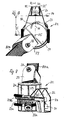
- the housing 20 is at its Top except with a cover 21, which gives access to the drive motor, provided with a to be recognized in Fig. 6 cover 22 for a guide housing 23 which serves to receive the steering shaft 80, which consists of two telescopically guided parts 80a and 80b here ,
- a steering wheel 70 is arranged, via which an operator, similar to the embodiment of Figs. 1 and 3, can exert a steering torque on the housing 20 of the lawnmower.
- the guide housing 23 is fixedly arranged in the interior of the housing 20. It consists, as shown in FIGS. 7 to 9, of a housing part not shown in detail firmly inserted into the housing 20, in which an approximately cylindrical bearing body 24 is rotatably held about the axis 25, characterized in that it is in a corresponding cylindrical guide 23 a the guide housing 23 is inserted and held with a flange 24a in a corresponding annular groove 23b of the guide housing.
- the bearing body 24 is provided with a in the embodiment at an angle ⁇ to a plane 29 inclined cylindrical guide 26, in which the cylindrical end of the steering shaft 80 is inserted.
- the steering shaft portion 80a is in the embodiment not of a continuous one-piece shaft portion, but from the end piece 80c, which runs in the guide 26 coaxial with the steering axis 10 and from a non-rotatably connected to this shaft end 80c tab 27, in turn, with the aid of a connecting pin 28 of Shaft part 80a removable, but is used in alignment with the shaft axis 10.
- the shaft part 80a with the shaft part 80b slidably held therein and the steering wheel 70 is therefore detachably arranged so that the lawnmower is not too bulky for transportation or storage purposes and takes up too much space.
- the counterforce caused by the exercise of this force in the direction of the arrow 34 is based on the steering shaft part 80c in the bearing body 24, which in turn in the opposite sense to the force of the arrow 34 presses against its guide housing 23 and so a force in the direction of the arrow 35th on the guide housing and on the housing 20 exerts.
- the two forces acting in the direction of the arrows 34 and 35 therefore, result in a torque on the housing 20 in the direction of the arrow 36, which acts around the vertical axis 11 and in the same manner as described with reference to the embodiment of FIGS. 1 to 3 , can be used to guide the lawn mower.
- the steering shaft 80 may, as already shown in Fig. 1, extend obliquely to this longitudinal axis 12 and also be pivoted relative to this during the machining process. This causes only a displacement of the slider 31 within the shaft 33, but does not question the operation of the steering operation in question.
- the steering shaft 80 which is formed rigidly transversely to its longitudinal axis 10
- a flexible shaft via which the desired torque can be introduced into the housing 20.
- the steering shaft 80 with the protruding arm 30 as an offset, but to equip them within the housing 20 with at least one bend, which exerts in the same manner as in the embodiment shown a lateral force in one direction on the housing 20 and in the longitudinal direction of the housing 20, ie in the direction of the longitudinal axis 12, offset thereto causes a counterforce in the opposite direction, which in turn serves to generate the desired torque on the housing 20.
- the new way of steering a cultivator therefore allows for the continuous change in the position of an operator to the device, without the steering ability of the device is affected.
Landscapes
- Life Sciences & Earth Sciences (AREA)
- Environmental Sciences (AREA)
- Harvester Elements (AREA)
- Steering-Linkage Mechanisms And Four-Wheel Steering (AREA)
- Guiding Agricultural Machines (AREA)
- Soil Working Implements (AREA)
- Transplanting Machines (AREA)
- Fertilizers (AREA)
- Pretreatment Of Seeds And Plants (AREA)
Claims (19)
- Appareil de traitement du sol transportable, en particulier tondeuse à gazon équipée d'un compartiment (2, 20) permettant de recueillir des éléments de traitement (5, 50) et d'un dispositif de guidage manipulé à la main par un technicien de service et placé sur le compartiment (2, 20) de manière rotative par rapport à un axe (11, 25) essentiellement vertical par rapport au plan de traitement (25), caractérisé en ce que le dispositif de guidage est muni d'un dispositif de direction rotatif (7, 8, 70, 80) dont le mouvement de rotation sur ou dans le compartiment (2, 20) peut être converti en un couple de rotation (36) autour d'un axe vertical (11, 25).
- Appareil de traitement du sol selon la revendication 1, caractérisé en ce que le dispositif de direction est composé d'un arbre de direction (8, 80) équipé d'une roue de direction (7, 70) adjacente au technicien de service ou d'un arceau de direction.
- Appareil de traitement du sol selon la revendication 2, caractérisé en ce que l'arbre de direction (8, 80) se présente sous forme d'arbre télescopique.
- Appareil de traitement du sol selon la revendication 2 ou 3, caractérisé en ce que l'arbre de direction 80 est orienté selon un angle prédéfini (β) par rapport au plan de traitement ou selon un plan parallèle (25) et est placé dans le compartiment (20) sur un corps de support (24) pouvant tourner autour de l'axe vertical (25) dans le compartiment (20).
- Appareil de traitement selon la revendication 4, caractérisé en ce que l'arbre de direction (80) coupe le corps de support (24) et vient s'engager sur une surface de contact (32) du compartiment (20) à l'aide d'au moins un coude (30), cette surface de contact étant placée au moins à la distance (a) du corps de support (24) dans une direction parallèle au plan de traitement.
- Appareil de traitement selon la revendication 5, caractérisé en ce que la surface de contact (32) est une partie d'un compartiment de guidage (23) contenu fixe dans le compartiment (20) pour le corps de support (24) formant une cheminée (33) avec des parois latérales (32, 32') orientées parallèlement au sens de déplacement (12) de l'appareil de traitement du sol, ces parois latérales servant alors de surfaces de contact.
- Appareil de traitement du sol selon la revendication 6, caractérisé en ce que le coude de l'arbre de direction (80) se présente sous forme de bras latéral (30), équipé en son extrémité libre d'un corps coulissant (31) amené aux deux parois latérales (32, 32') de la cheminée (33).
- Appareil de traitement du sol selon la revendication 7, caractérisé en ce que le corps coulissant (31) est de rotation symétrique.
- Appareil de traitement du sol selon la revendication 7, caractérisé en ce que le corps coulissant (31) vient s'engager de manière rotative sur le bras (30).
- Appareil de traitement du sol selon la revendication 5, caractérisé en ce que l'arbre de direction (8, 80) vient s'engager de manière articulée sur le côté du corps de support servant au technicien de service.
- Appareil de traitement du sol selon la revendication 10, caractérisé en ce qu'une articulation croisée est proposée comme articulation.
- Appareil de traitement du sol selon la revendication 2, caractérisé en ce que l'arbre de direction (8) est équipé, au niveau de l'extrémité adjacente au compartiment (2), d'une roue conique (16) interagissant avec un disque denté (17) correspondant fixé sur le compartiment (2).
- Appareil de traitement du sol selon la revendication 2, caractérisé en ce que l'arbre de direction se présente sous forme d'arbre flexible.
- Appareil de traitement du sol selon la revendication 13, caractérisé en ce que l'arbre flexible est amené dans un corps de support tournant autour d'un axe vertical (11).
- Appareil de traitement du sol selon la revendication 1, caractérisé en ce que le compartiment (2, 20) comprend des roues avant et arrière (3, 4 ; 30, 41) et en ce que l'axe vertical (11, 25) se trouve entre les roues avant et arrière.
- Appareil de traitement du sol selon la revendication 15, caractérisé en ce que la distance de l'axe vertical (11, 25) dans la partie longitudinale du compartiment (2, 20) représente moins de 30 % de la distance entre les essieux avant et arrière.
- Appareil de traitement du sol selon la revendication 16, caractérisé en ce que l'agencement avant présente un ou deux roulements de direction.
- Appareil de traitement du sol selon la revendication 16, caractérisé en ce que les agencements de roues ne peuvent pas être dirigés et en ce que les surfaces de roulement (13) des roues (4a) présentent une faible résistance au glissement par rapport au déplacement latéral.
- Appareil de traitement du sol selon la revendication 1, caractérisé en ce que le dispositif de guidage (8, 80) vient s'engager de manière amovible sur le compartiment (2, 20).
Applications Claiming Priority (3)
| Application Number | Priority Date | Filing Date | Title |
|---|---|---|---|
| DE10105005 | 2001-02-03 | ||
| DE10105005 | 2001-02-03 | ||
| PCT/EP2002/001059 WO2002062126A1 (fr) | 2001-02-03 | 2002-02-01 | Machine roulante pour le travail du sol, en particulier tondeuse a gazon |
Publications (2)
| Publication Number | Publication Date |
|---|---|
| EP1357782A1 EP1357782A1 (fr) | 2003-11-05 |
| EP1357782B1 true EP1357782B1 (fr) | 2006-07-26 |
Family
ID=7672813
Family Applications (1)
| Application Number | Title | Priority Date | Filing Date |
|---|---|---|---|
| EP02702336A Expired - Lifetime EP1357782B1 (fr) | 2001-02-03 | 2002-02-01 | Machine roulante pour le travail du sol, en particulier tondeuse a gazon |
Country Status (9)
| Country | Link |
|---|---|
| US (2) | US20050097875A1 (fr) |
| EP (1) | EP1357782B1 (fr) |
| CN (1) | CN1250069C (fr) |
| AT (1) | ATE333781T1 (fr) |
| CA (1) | CA2435943A1 (fr) |
| DE (1) | DE50207635D1 (fr) |
| DK (1) | DK1357782T3 (fr) |
| WO (1) | WO2002062126A1 (fr) |
| ZA (1) | ZA200305916B (fr) |
Families Citing this family (14)
| Publication number | Priority date | Publication date | Assignee | Title |
|---|---|---|---|---|
| DE10214679A1 (de) * | 2002-03-28 | 2003-10-30 | Gardena Kress & Kastner Gmbh | Bodenbearbeitungsgerät, insbesondere Rasenmäher |
| USD508924S1 (en) | 2004-02-14 | 2005-08-30 | Gardena Manufacturing Gmbh | Lawn mower |
| USD514130S1 (en) | 2004-08-11 | 2006-01-31 | Gardena Manufacturing Gmbh | Lawnmower |
| USD517093S1 (en) | 2004-08-11 | 2006-03-14 | Gardena Manufacturing Gmbh | Lawn rake |
| USD514129S1 (en) | 2004-08-11 | 2006-01-31 | Gardana Manufacturing Gmbh | Lawnmower |
| WO2015037030A1 (fr) | 2013-09-10 | 2015-03-19 | 株式会社北村製作所 | Corps rotatif, tondeuse et procédé de tonte d'herbe |
| US9616893B2 (en) | 2014-10-15 | 2017-04-11 | Honda Motor Co., Ltd. | Automatic turn-sensing ground speed reduction systems and related methods for walk-behind machines |
| CA2987454A1 (fr) | 2015-06-05 | 2016-12-08 | Mtd Products Inc | Tondeuse poussee avec commande a volant de direction |
| GR20150100444A (el) * | 2015-10-15 | 2017-07-03 | Αλεξανδρος Νικολαου Γιαννακοπουλος | Αμφιπλευρα τηλεσκοπικος βραχιονας θαμνοκοπτικου μηχανηματος με ανακλινομενες χειρολαβες |
| US11116130B2 (en) * | 2016-08-09 | 2021-09-14 | Ariens Company | Utility machine operable in stand-on and walk-behind modes |
| US10588257B2 (en) | 2017-10-06 | 2020-03-17 | Black & Decker, Inc. | Pivoting handle assembly |
| CN107838500B (zh) * | 2017-12-06 | 2023-12-12 | 盛瑞传动股份有限公司 | 一种移动式大型切割装置 |
| CN108401642A (zh) * | 2018-03-02 | 2018-08-17 | 宁波大叶园林设备股份有限公司 | 用电动减速器前方向左右驱动双万向轮的草坪割草机 |
| US11297766B1 (en) * | 2019-11-26 | 2022-04-12 | Stefanie Wynn-Grayson | Standing motorized lawn mower with sulky and steering column |
Family Cites Families (25)
| Publication number | Priority date | Publication date | Assignee | Title |
|---|---|---|---|---|
| US456472A (en) * | 1891-07-21 | bratjn | ||
| US1876963A (en) * | 1930-05-07 | 1932-09-13 | Carl C Klass | Lawn mower |
| US2038697A (en) * | 1933-05-12 | 1936-04-28 | Edward N Winslow | Manually operated tool |
| US2727753A (en) * | 1952-12-08 | 1955-12-20 | Foley Mfg Company | Adjustable lawn mower handle |
| US2809490A (en) * | 1953-10-06 | 1957-10-15 | Richard T Oeters | Handle for lawn mowers |
| US3029887A (en) * | 1960-12-14 | 1962-04-17 | Socrates J Schantz | Power mower having drive wheels controllable by rotatable handle |
| US3196971A (en) * | 1961-05-31 | 1965-07-27 | Socrates J Schantz | Power mower with gear driven steering mechanism |
| US3130444A (en) * | 1962-05-10 | 1964-04-28 | Charles V Stollsteimer | Auxiliary handle for power lawn mowers |
| US3382653A (en) * | 1964-10-16 | 1968-05-14 | Buigne Frank De | Power driven rotary mower |
| DE2448129A1 (de) * | 1974-10-09 | 1976-04-22 | Gerhard Dr Ing Maerz | Rasenmaeher mit schwenkbarem fuehrungsbuegel |
| US4396067A (en) * | 1978-06-19 | 1983-08-02 | Gilson Brothers Company | Tiller with rotatable tines and guiding handle |
| US4244427A (en) * | 1978-06-19 | 1981-01-13 | Gilson Brothers Company | Tiller with rotatable tines and guiding handle |
| IT1180901B (it) * | 1984-07-31 | 1987-09-23 | Bedogni & C Srl Off Mec | Manubrio girevole,in particolare per macchine tosaerba |
| GB2164233B (en) * | 1984-09-13 | 1987-10-07 | Honda Motor Co Ltd | Power grass mower |
| CH678044A5 (en) * | 1985-05-31 | 1991-07-31 | Rapid Masch Fahrzeuge Ag | Steering mechanism for two-wheel lawn mower |
| US4998948A (en) * | 1989-12-04 | 1991-03-12 | Scag Power Equipment, Inc. | Lawn mower |
| JPH0538218A (ja) * | 1991-07-15 | 1993-02-19 | Kubota Corp | 歩行型芝刈機 |
| US5580314A (en) * | 1993-03-29 | 1996-12-03 | Nsk Ltd. | Energy absorbing intermediate shaft |
| US5713420A (en) * | 1995-08-28 | 1998-02-03 | Garden Way, Incorporated | Convertible garden tiller |
| JP2917132B2 (ja) * | 1997-01-13 | 1999-07-12 | 農林水産省四国農業試験場長 | 車輪走行式刈払機 |
| US5816614A (en) * | 1997-03-21 | 1998-10-06 | Burke, Inc. | Tiller assembly for personal mobility vehicles |
| EP0915002A1 (fr) * | 1997-11-07 | 1999-05-12 | Wandfluh AG | Direction pour véhicule |
| US6131689A (en) * | 1998-12-11 | 2000-10-17 | Deere & Company | All-wheel-steer biasing mechanism |
| US20030041578A1 (en) * | 2001-08-31 | 2003-03-06 | Fuller Joseph B. | Wheeled trimmer |
| USD508924S1 (en) * | 2004-02-14 | 2005-08-30 | Gardena Manufacturing Gmbh | Lawn mower |
-
2002
- 2002-02-01 DK DK02702336T patent/DK1357782T3/da active
- 2002-02-01 CA CA002435943A patent/CA2435943A1/fr not_active Abandoned
- 2002-02-01 US US10/467,030 patent/US20050097875A1/en not_active Abandoned
- 2002-02-01 AT AT02702336T patent/ATE333781T1/de not_active IP Right Cessation
- 2002-02-01 WO PCT/EP2002/001059 patent/WO2002062126A1/fr not_active Ceased
- 2002-02-01 CN CNB028075943A patent/CN1250069C/zh not_active Expired - Fee Related
- 2002-02-01 DE DE50207635T patent/DE50207635D1/de not_active Expired - Lifetime
- 2002-02-01 EP EP02702336A patent/EP1357782B1/fr not_active Expired - Lifetime
-
2003
- 2003-07-31 ZA ZA200305916A patent/ZA200305916B/en unknown
-
2005
- 2005-09-06 US US11/220,088 patent/US20060076152A1/en not_active Abandoned
Also Published As
| Publication number | Publication date |
|---|---|
| ZA200305916B (en) | 2004-08-27 |
| ATE333781T1 (de) | 2006-08-15 |
| CN1250069C (zh) | 2006-04-12 |
| DE50207635D1 (de) | 2006-09-07 |
| EP1357782A1 (fr) | 2003-11-05 |
| WO2002062126A1 (fr) | 2002-08-15 |
| CA2435943A1 (fr) | 2002-08-15 |
| US20050097875A1 (en) | 2005-05-12 |
| DK1357782T3 (da) | 2006-11-27 |
| US20060076152A1 (en) | 2006-04-13 |
| CN1499924A (zh) | 2004-05-26 |
Similar Documents
| Publication | Publication Date | Title |
|---|---|---|
| EP1357782A1 (fr) | Machine roulante pour le travail du sol, en particulier tondeuse a gazon | |
| DE69628598T2 (de) | Heuwerbungsmaschine | |
| EP0426960A2 (fr) | Bineuse pour machine agricole | |
| EP0355365B1 (fr) | Tondeuse à gazon | |
| DE69403511T2 (de) | Heuwerbungsmaschine | |
| EP0289773A1 (fr) | Dispositif d'attelage agricole | |
| EP0807376A2 (fr) | Protection de collision pour une faucheuse connectable à un véhicule | |
| DE69512559T2 (de) | Heuwerbungsmaschine, insbesondere ein Schwader für Futter | |
| DE69304558T2 (de) | Heuwerbungsmaschine mit einem mit gesteuerten Stützrädern versehenen Rahmen | |
| DE3038046C2 (de) | Vorrichtung zum Bodenbearbeiten, insbesondere für Garten- und Parkanlagen | |
| DE69409149T2 (de) | Landwirtschaftliche Maschine, insbesondere ein Futterschwader | |
| DE3502658A1 (de) | Walzenkruemler | |
| EP0383013A2 (fr) | Rouleau compacteur | |
| WO2006072364A1 (fr) | Herse a disques | |
| DE3546342C2 (fr) | ||
| AT392718B (de) | Heuwerbungsmaschine | |
| AT526592B1 (de) | Selbstfahrendes einachsiges fahrzeug | |
| DE102004025478B4 (de) | Landwirtschaftliche Maschine | |
| EP0509307B1 (fr) | Tondeuse attachable à un tracteur au moyen d'une barre de traction | |
| DE102018132677A1 (de) | Handgeführter Rasenmäher, insbesondere Sichelmäher | |
| EP1081288B1 (fr) | Balayeuse | |
| DE4341892A1 (de) | Vorrichtung zum Bearbeiten von Pflanzen, insbesondere von Hecken | |
| DE4218069A1 (de) | Selbstfahrende Arbeitsgerätschaft | |
| EP1461990B1 (fr) | Tondeuse à gazon dirigeable et motorisée | |
| DE933538C (de) | Landwirtschaftlicher Schlepper mit Maehwerk |
Legal Events
| Date | Code | Title | Description |
|---|---|---|---|
| PUAI | Public reference made under article 153(3) epc to a published international application that has entered the european phase |
Free format text: ORIGINAL CODE: 0009012 |
|
| 17P | Request for examination filed |
Effective date: 20030725 |
|
| AK | Designated contracting states |
Kind code of ref document: A1 Designated state(s): AT BE CH CY DE DK ES FI FR GB GR IE IT LI LU MC NL PT SE TR |
|
| AX | Request for extension of the european patent |
Extension state: AL LT LV MK RO SI |
|
| GRAP | Despatch of communication of intention to grant a patent |
Free format text: ORIGINAL CODE: EPIDOSNIGR1 |
|
| GRAS | Grant fee paid |
Free format text: ORIGINAL CODE: EPIDOSNIGR3 |
|
| GRAA | (expected) grant |
Free format text: ORIGINAL CODE: 0009210 |
|
| AK | Designated contracting states |
Kind code of ref document: B1 Designated state(s): AT BE CH CY DE DK ES FI FR GB GR IE IT LI LU MC NL PT SE TR |
|
| PG25 | Lapsed in a contracting state [announced via postgrant information from national office to epo] |
Ref country code: IT Free format text: LAPSE BECAUSE OF FAILURE TO SUBMIT A TRANSLATION OF THE DESCRIPTION OR TO PAY THE FEE WITHIN THE PRESCRIBED TIME-LIMIT;WARNING: LAPSES OF ITALIAN PATENTS WITH EFFECTIVE DATE BEFORE 2007 MAY HAVE OCCURRED AT ANY TIME BEFORE 2007. THE CORRECT EFFECTIVE DATE MAY BE DIFFERENT FROM THE ONE RECORDED. Effective date: 20060726 Ref country code: IE Free format text: LAPSE BECAUSE OF FAILURE TO SUBMIT A TRANSLATION OF THE DESCRIPTION OR TO PAY THE FEE WITHIN THE PRESCRIBED TIME-LIMIT Effective date: 20060726 Ref country code: FI Free format text: LAPSE BECAUSE OF FAILURE TO SUBMIT A TRANSLATION OF THE DESCRIPTION OR TO PAY THE FEE WITHIN THE PRESCRIBED TIME-LIMIT Effective date: 20060726 |
|
| REG | Reference to a national code |
Ref country code: GB Ref legal event code: FG4D Free format text: NOT ENGLISH |
|
| REG | Reference to a national code |
Ref country code: CH Ref legal event code: EP |
|
| REG | Reference to a national code |
Ref country code: IE Ref legal event code: FG4D Free format text: LANGUAGE OF EP DOCUMENT: GERMAN |
|
| REF | Corresponds to: |
Ref document number: 50207635 Country of ref document: DE Date of ref document: 20060907 Kind code of ref document: P |
|
| REG | Reference to a national code |
Ref country code: SE Ref legal event code: TRGR |
|
| GBT | Gb: translation of ep patent filed (gb section 77(6)(a)/1977) |
Effective date: 20060925 |
|
| PG25 | Lapsed in a contracting state [announced via postgrant information from national office to epo] |
Ref country code: ES Free format text: LAPSE BECAUSE OF FAILURE TO SUBMIT A TRANSLATION OF THE DESCRIPTION OR TO PAY THE FEE WITHIN THE PRESCRIBED TIME-LIMIT Effective date: 20061106 |
|
| REG | Reference to a national code |
Ref country code: CH Ref legal event code: NV Representative=s name: ZIMMERLI, WAGNER & PARTNER AG |
|
| REG | Reference to a national code |
Ref country code: DK Ref legal event code: T3 |
|
| PG25 | Lapsed in a contracting state [announced via postgrant information from national office to epo] |
Ref country code: PT Free format text: LAPSE BECAUSE OF FAILURE TO SUBMIT A TRANSLATION OF THE DESCRIPTION OR TO PAY THE FEE WITHIN THE PRESCRIBED TIME-LIMIT Effective date: 20061226 |
|
| ET | Fr: translation filed | ||
| REG | Reference to a national code |
Ref country code: IE Ref legal event code: FD4D |
|
| PG25 | Lapsed in a contracting state [announced via postgrant information from national office to epo] |
Ref country code: MC Free format text: LAPSE BECAUSE OF NON-PAYMENT OF DUE FEES Effective date: 20070228 |
|
| PLBE | No opposition filed within time limit |
Free format text: ORIGINAL CODE: 0009261 |
|
| STAA | Information on the status of an ep patent application or granted ep patent |
Free format text: STATUS: NO OPPOSITION FILED WITHIN TIME LIMIT |
|
| 26N | No opposition filed |
Effective date: 20070427 |
|
| PG25 | Lapsed in a contracting state [announced via postgrant information from national office to epo] |
Ref country code: GR Free format text: LAPSE BECAUSE OF FAILURE TO SUBMIT A TRANSLATION OF THE DESCRIPTION OR TO PAY THE FEE WITHIN THE PRESCRIBED TIME-LIMIT Effective date: 20061027 |
|
| PGFP | Annual fee paid to national office [announced via postgrant information from national office to epo] |
Ref country code: CH Payment date: 20080225 Year of fee payment: 7 Ref country code: DK Payment date: 20080226 Year of fee payment: 7 |
|
| PGFP | Annual fee paid to national office [announced via postgrant information from national office to epo] |
Ref country code: GB Payment date: 20080222 Year of fee payment: 7 Ref country code: NL Payment date: 20080220 Year of fee payment: 7 Ref country code: SE Payment date: 20080225 Year of fee payment: 7 |
|
| PGFP | Annual fee paid to national office [announced via postgrant information from national office to epo] |
Ref country code: BE Payment date: 20081229 Year of fee payment: 8 |
|
| PGFP | Annual fee paid to national office [announced via postgrant information from national office to epo] |
Ref country code: AT Payment date: 20081229 Year of fee payment: 8 |
|
| PG25 | Lapsed in a contracting state [announced via postgrant information from national office to epo] |
Ref country code: CY Free format text: LAPSE BECAUSE OF FAILURE TO SUBMIT A TRANSLATION OF THE DESCRIPTION OR TO PAY THE FEE WITHIN THE PRESCRIBED TIME-LIMIT Effective date: 20060726 Ref country code: LU Free format text: LAPSE BECAUSE OF NON-PAYMENT OF DUE FEES Effective date: 20070201 |
|
| PG25 | Lapsed in a contracting state [announced via postgrant information from national office to epo] |
Ref country code: TR Free format text: LAPSE BECAUSE OF FAILURE TO SUBMIT A TRANSLATION OF THE DESCRIPTION OR TO PAY THE FEE WITHIN THE PRESCRIBED TIME-LIMIT Effective date: 20060726 |
|
| REG | Reference to a national code |
Ref country code: CH Ref legal event code: PL |
|
| EUG | Se: european patent has lapsed | ||
| REG | Reference to a national code |
Ref country code: DK Ref legal event code: EBP |
|
| GBPC | Gb: european patent ceased through non-payment of renewal fee |
Effective date: 20090201 |
|
| PG25 | Lapsed in a contracting state [announced via postgrant information from national office to epo] |
Ref country code: LI Free format text: LAPSE BECAUSE OF NON-PAYMENT OF DUE FEES Effective date: 20090228 Ref country code: CH Free format text: LAPSE BECAUSE OF NON-PAYMENT OF DUE FEES Effective date: 20090228 |
|
| PGFP | Annual fee paid to national office [announced via postgrant information from national office to epo] |
Ref country code: FR Payment date: 20081219 Year of fee payment: 8 |
|
| NLV4 | Nl: lapsed or anulled due to non-payment of the annual fee |
Effective date: 20090901 |
|
| PG25 | Lapsed in a contracting state [announced via postgrant information from national office to epo] |
Ref country code: NL Free format text: LAPSE BECAUSE OF NON-PAYMENT OF DUE FEES Effective date: 20090901 |
|
| PG25 | Lapsed in a contracting state [announced via postgrant information from national office to epo] |
Ref country code: GB Free format text: LAPSE BECAUSE OF NON-PAYMENT OF DUE FEES Effective date: 20090201 |
|
| PG25 | Lapsed in a contracting state [announced via postgrant information from national office to epo] |
Ref country code: DK Free format text: LAPSE BECAUSE OF NON-PAYMENT OF DUE FEES Effective date: 20090831 |
|
| BERE | Be: lapsed |
Owner name: *GARDENA MANUFACTURING G.M.B.H. Effective date: 20100228 |
|
| REG | Reference to a national code |
Ref country code: FR Ref legal event code: ST Effective date: 20101029 |
|
| PG25 | Lapsed in a contracting state [announced via postgrant information from national office to epo] |
Ref country code: AT Free format text: LAPSE BECAUSE OF NON-PAYMENT OF DUE FEES Effective date: 20100201 |
|
| PG25 | Lapsed in a contracting state [announced via postgrant information from national office to epo] |
Ref country code: FR Free format text: LAPSE BECAUSE OF NON-PAYMENT OF DUE FEES Effective date: 20100301 |
|
| PG25 | Lapsed in a contracting state [announced via postgrant information from national office to epo] |
Ref country code: BE Free format text: LAPSE BECAUSE OF NON-PAYMENT OF DUE FEES Effective date: 20100228 |
|
| PG25 | Lapsed in a contracting state [announced via postgrant information from national office to epo] |
Ref country code: SE Free format text: LAPSE BECAUSE OF NON-PAYMENT OF DUE FEES Effective date: 20090202 |
|
| REG | Reference to a national code |
Ref country code: DE Ref legal event code: R081 Ref document number: 50207635 Country of ref document: DE Owner name: HUSQVARNA AB, SE Free format text: FORMER OWNER: GARDENA MANUFACTURING GMBH, 89079 ULM, DE Effective date: 20140627 |
|
| PGFP | Annual fee paid to national office [announced via postgrant information from national office to epo] |
Ref country code: DE Payment date: 20151218 Year of fee payment: 15 |
|
| REG | Reference to a national code |
Ref country code: DE Ref legal event code: R119 Ref document number: 50207635 Country of ref document: DE |
|
| PG25 | Lapsed in a contracting state [announced via postgrant information from national office to epo] |
Ref country code: DE Free format text: LAPSE BECAUSE OF NON-PAYMENT OF DUE FEES Effective date: 20170901 |