EP1358820A2 - Träger für Regal, bestehend aus einem solchen Träger - Google Patents
Träger für Regal, bestehend aus einem solchen Träger Download PDFInfo
- Publication number
- EP1358820A2 EP1358820A2 EP03370020A EP03370020A EP1358820A2 EP 1358820 A2 EP1358820 A2 EP 1358820A2 EP 03370020 A EP03370020 A EP 03370020A EP 03370020 A EP03370020 A EP 03370020A EP 1358820 A2 EP1358820 A2 EP 1358820A2
- Authority
- EP
- European Patent Office
- Prior art keywords
- cleat
- angle
- hooking
- wall
- main wall
- Prior art date
- Legal status (The legal status is an assumption and is not a legal conclusion. Google has not performed a legal analysis and makes no representation as to the accuracy of the status listed.)
- Withdrawn
Links
- 229910000746 Structural steel Inorganic materials 0.000 claims description 13
- 238000003780 insertion Methods 0.000 claims description 6
- 230000037431 insertion Effects 0.000 claims description 6
- 230000000295 complement effect Effects 0.000 claims description 3
- 230000002787 reinforcement Effects 0.000 claims description 3
- 229910001092 metal group alloy Inorganic materials 0.000 claims description 2
- 230000003014 reinforcing effect Effects 0.000 description 4
- 238000009434 installation Methods 0.000 description 2
- 241000861223 Issus Species 0.000 description 1
- 229910000831 Steel Inorganic materials 0.000 description 1
- 240000008042 Zea mays Species 0.000 description 1
- 230000000694 effects Effects 0.000 description 1
- 239000002184 metal Substances 0.000 description 1
- 229910052751 metal Inorganic materials 0.000 description 1
- 239000010959 steel Substances 0.000 description 1
Images


Classifications
-
- A—HUMAN NECESSITIES
- A47—FURNITURE; DOMESTIC ARTICLES OR APPLIANCES; COFFEE MILLS; SPICE MILLS; SUCTION CLEANERS IN GENERAL
- A47B—TABLES; DESKS; OFFICE FURNITURE; CABINETS; DRAWERS; GENERAL DETAILS OF FURNITURE
- A47B57/00—Cabinets, racks or shelf units, characterised by features for adjusting shelves or partitions
- A47B57/30—Cabinets, racks or shelf units, characterised by features for adjusting shelves or partitions with means for adjusting the height of detachable shelf supports
- A47B57/40—Cabinets, racks or shelf units, characterised by features for adjusting shelves or partitions with means for adjusting the height of detachable shelf supports consisting of hooks coacting with openings
- A47B57/406—Hooks attached to uprights
-
- A—HUMAN NECESSITIES
- A47—FURNITURE; DOMESTIC ARTICLES OR APPLIANCES; COFFEE MILLS; SPICE MILLS; SUCTION CLEANERS IN GENERAL
- A47B—TABLES; DESKS; OFFICE FURNITURE; CABINETS; DRAWERS; GENERAL DETAILS OF FURNITURE
- A47B96/00—Details of cabinets, racks or shelf units not covered by a single one of groups A47B43/00 - A47B95/00; General details of furniture
- A47B96/14—Bars, uprights, struts, or like supports, for cabinets, brackets, or the like
- A47B96/1441—Horizontal struts
Definitions
- the invention relates to the technical field of shelving and relates more particularly to cleats or support bars for shelves, trays or the like.
- cleats are intended to be hung on vertical profiles including hanging lights.
- the document EP-0.421.905 describes a cleat with a C section, comprising a core and two longitudinal reinforcing wings, the core being provided with a deep-drawn and folded central tongue forming a support surface for a shelf reinforcement profile.
- the cleat includes, at each end, an attachment appendix provided with mounting tabs stamped, these tabs being intended to be inserted by force into shelf upright perforations. Snap tabs extend substantially in the same plane as the core of the cleat.
- the invention aims to provide a support bracket for a shelf, adapted to the realization of rigid shelving, this cleat can be manufactured so economical using simple tools, mounting and dismounting this cleat on uprights of conventional type being possible without tools specific.
- the cleat can thus be used by people more or less inexperienced in minimum time
- the invention further aims to provide a cleat which has a ratio high between mechanical resistance and linear density.
- the invention relates, according to a first aspect to a cleat shelving unit comprising a main wall and two end parts each provided with means for hanging on an upright, one of these two end parts comprising a hooking section and a wing, the section of attachment being provided with means capable of ensuring the mounting of the part end of the cleat on an upright, the wing forming an angle with the section hooking.
- the invention relates, according to a second aspect, to an assembly formed by a first cleat as defined above and a second cleat comprising a main wall, one of the end parts of which comprises a attachment section provided with means suitable for mounting the extreme part of this second cleat on the wing of the first cleat.
- the invention relates, according to a third aspect, to shelving comprising at least a first cleat as presented above, this first cleat being fixed on an upright provided with mounting means complementary to those placed on this first batten.
- the invention relates, according to a fourth aspect, to shelving comprising at least one assembly as presented above, the first and / or the second cleat being fixed on an upright provided with mounting means complementary to those arranged on these cleats.
- the shelving comprises four substantially identical and vertical uprights and at least one support frame for shelf, this support frame coming from the assembly of four battens, know two first battens substantially parallel to each other, and two second battens substantially parallel to each other.
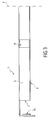
- the cleat 1 is shown in Figure 1 laid flat on its largest wall 2, subsequently designated by the expression “main wall”.
- depth will be used with reference to a third direction D3, the three directions D1, D2 and D3 forming a trihedron direct.
- the cleat 1 has a plane of symmetry whose trace in the plane of Figure 1 appears in phantom under the reference T. This plane of symmetry is substantially perpendicular to the plan of figure 1. Because of this symmetry, only half of the cleat 1 is seen in figure 1.
- the cleat may be provided with a first end part as shown in Figure 1, the other the extreme part of this cleat being different and of a type known per se.
- the main wall 2 is of generally rectangular outline, in the mode for carrying out FIG. 1. It goes without saying that the lower free edge 3 of the wall main 2 can be longitudinal and straight (as for the embodiment shown) or even curved, depending in particular on the aesthetic effect and the resistance sought.
- the main wall 2 is extended, opposite the lower free edge 3, by an angle iron 4 comprising a support wall 5 substantially perpendicular to the main wall 2 and a reinforcing wall 6 substantially perpendicular to the support wall 5.
- the angle iron 4 does not extend over all the length of the main wall 2, the transverse free edge 7 of this angle 4 being placed at a distance Da1 from the transverse edge 8 of the main wall 2.
- This distance Da1 corresponds to the length of a hooking section 9 of the bracket 1 on an upright, not shown.
- this attachment is obtained using a means known per se: a through hole 10 formed in section 9, is intended to come to rest in support a tab arranged on the upright.
- the section 9 comprises a first through hole 10, and a lower free edge 11 of shape adapted to receive in support a second leg projecting from the shelving upright.
- the substantially square through hole 10 is arranged as follows above the crenelated free edge 11 of section 9, this free edge 11 being of superimposable shape, by translation along D2, with the through hole 10.
- the cleat can be provided with more than one through hole 10, all of these through holes being substantially aligned in the direction D2.
- the angle iron 4 is provided, from place to place, with notches 12 allowing the installation and support of support bars for shelving shelves. If necessary, these support bars can be forced into the notches 12.
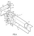
- the cleat 1 comprises a wing 13, substantially perpendicular to the main wall 2.
- This wing 13 is provided with means of assembly to a second cleat 14.
- the second cleat 14 comprises, just like the first cleat 1, a main wall 20 of substantially rectangular outline.
- the edge upper part of this main wall is extended by an angle including a support wall 21 coming substantially in the plane of extension of the wall support 5 of the first cleat 1, when the two cleats 1.14 are assembled.
- the angle of the second cleat 14 does not extend over the entire dimension of the main wall 20, but stops at a distance Da2 from the edge transverse free 22 of the main wall 20, this distance Da2 corresponding to the width of the attachment section 23 of the second cleat 14.
- This distance Da2 is substantially equal to or slightly less than the width La13 of wing 13.
- the two battens 1.14 shelf shelf support are intended to be placed substantially perpendicular to each other, one of the battens forming the largest dimension of the shelving.
- the angle between the hooking section 9 and the wing 13 is different from 90 °, for example of the order by 60 °, so as to allow the installation of shelving, one of the shelf angles are not straight but close to 60 °.
- the shelf support bracket which has just been described is suitable for the realization of rigid shelving, this cleat can be manufactured so economical by using simple tools, in particular for folding and delivery of metal such as sheet steel.
- the cleat can thus be used by people more or less inexperienced in a minimum of time.
Landscapes
- Supports Or Holders For Household Use (AREA)
Applications Claiming Priority (2)
| Application Number | Priority Date | Filing Date | Title |
|---|---|---|---|
| FR0205565 | 2002-05-03 | ||
| FR0205565A FR2839251A1 (fr) | 2002-05-03 | 2002-05-03 | Tasseau de rayonnage et rayonnage comprenant un tel tasseau |
Publications (2)
| Publication Number | Publication Date |
|---|---|
| EP1358820A2 true EP1358820A2 (de) | 2003-11-05 |
| EP1358820A3 EP1358820A3 (de) | 2004-01-14 |
Family
ID=28800128
Family Applications (1)
| Application Number | Title | Priority Date | Filing Date |
|---|---|---|---|
| EP03370020A Withdrawn EP1358820A3 (de) | 2002-05-03 | 2003-05-05 | Träger für Regal, umfassend einen solchen Träger |
Country Status (2)
| Country | Link |
|---|---|
| EP (1) | EP1358820A3 (de) |
| FR (1) | FR2839251A1 (de) |
Cited By (4)
| Publication number | Priority date | Publication date | Assignee | Title |
|---|---|---|---|---|
| ITVI20090305A1 (it) * | 2009-12-23 | 2011-06-24 | Cbs S R L | Traversa con connessione mobile per scaffalature |
| CN106473485A (zh) * | 2015-09-02 | 2017-03-08 | 森特士兴集团股份有限公司 | 一种隔板支架及储物柜隔层 |
| GB2546070A (en) * | 2016-01-05 | 2017-07-12 | Hurst David | An airing cupboard bracket |
| US20220071388A1 (en) * | 2020-09-08 | 2022-03-10 | Grillnetics LLC | Enclosure Assembly System |
Citations (1)
| Publication number | Priority date | Publication date | Assignee | Title |
|---|---|---|---|---|
| EP0421905A1 (de) | 1989-10-04 | 1991-04-10 | Technique Nouvelled'assemblage Et De Construction - Tixit, S.A. | Regalvorrichtung |
Family Cites Families (4)
| Publication number | Priority date | Publication date | Assignee | Title |
|---|---|---|---|---|
| FR2579431B1 (fr) * | 1985-03-28 | 1988-02-05 | Bastiani Jacques | Rayonnage metallique automontable embouti |
| DE3709003A1 (de) * | 1987-03-19 | 1988-10-06 | Niedax Gmbh | Kupplung zum verbinden von mit lochungen, bzw. in die lochungen einbring- und festlegbaren ansaetzen versehenen profilstaeben |
| DE69810258D1 (de) * | 1998-01-30 | 2003-01-30 | Losey Ltd | Modulare Struktur für Metallregale oder dergleichen |
| DK1129644T3 (da) * | 2000-03-03 | 2003-02-10 | Meta Regalbau Gmbh & Co Kg | Reol |
-
2002
- 2002-05-03 FR FR0205565A patent/FR2839251A1/fr active Pending
-
2003
- 2003-05-05 EP EP03370020A patent/EP1358820A3/de not_active Withdrawn
Patent Citations (1)
| Publication number | Priority date | Publication date | Assignee | Title |
|---|---|---|---|---|
| EP0421905A1 (de) | 1989-10-04 | 1991-04-10 | Technique Nouvelled'assemblage Et De Construction - Tixit, S.A. | Regalvorrichtung |
Cited By (7)
| Publication number | Priority date | Publication date | Assignee | Title |
|---|---|---|---|---|
| ITVI20090305A1 (it) * | 2009-12-23 | 2011-06-24 | Cbs S R L | Traversa con connessione mobile per scaffalature |
| CN106473485A (zh) * | 2015-09-02 | 2017-03-08 | 森特士兴集团股份有限公司 | 一种隔板支架及储物柜隔层 |
| GB2546070A (en) * | 2016-01-05 | 2017-07-12 | Hurst David | An airing cupboard bracket |
| GB2546070B (en) * | 2016-01-05 | 2021-03-10 | Hurst David | An airing cupboard bracket |
| US20220071388A1 (en) * | 2020-09-08 | 2022-03-10 | Grillnetics LLC | Enclosure Assembly System |
| US11700937B2 (en) * | 2020-09-08 | 2023-07-18 | Grillnetics LLC | Enclosure assembly system |
| US12268300B2 (en) | 2020-09-08 | 2025-04-08 | Grillnetics LLC | Enclosure assembly system |
Also Published As
| Publication number | Publication date |
|---|---|
| EP1358820A3 (de) | 2004-01-14 |
| FR2839251A1 (fr) | 2003-11-07 |
Similar Documents
| Publication | Publication Date | Title |
|---|---|---|
| BE1022779A1 (fr) | Systeme d'assemblage de panneaux suivant un diedre pour realiser un meuble et meuble ainsi realise | |
| CH631062A5 (fr) | Dispositif d'exposition mural. | |
| FR2880780A1 (fr) | Systeme d'etageres, adaptateur, chassis d'etagere, rail de support et procede de realisation d'un systeme d'etagere | |
| CA1050489A (fr) | Dispositif d'assemblage entre montants et traverses pour l'execution de structures metalliques | |
| FR2975573A1 (fr) | Element profile pour des meubles, notamment des etageres | |
| EP0085630A1 (de) | Trennwand bestehend aus auf einem Skelett befestigten Platten, sowie Platte für eine derartige Trennwand | |
| EP0760546B1 (de) | Befestigungsgestell, insbesondere für elektrische Apparate | |
| FR2839251A1 (fr) | Tasseau de rayonnage et rayonnage comprenant un tel tasseau | |
| FR2730771A1 (fr) | Ecrou encage a montage sur une piece en forme d'equerre | |
| FR2548002A1 (fr) | Ensemble cremaillere-console perfectionne destine au rangement avec fixation sur parois | |
| FR2738445A1 (fr) | Accessoire de support pour l'assujettissement d'un barreau a un autre element de chassis, notamment pour le support d'appareils electriques | |
| JP5292597B2 (ja) | 椅子 | |
| FR2634259A1 (fr) | Systeme d'assemblage pour la realisation d'objets divers du type meuble notamment | |
| FR2501984A1 (de) | ||
| FR2468023A1 (fr) | Dispositif d'assemblage de plaques et de barres pour constituer des meubles tels que presentoirs | |
| FR2965707A1 (fr) | Dispositif de fixation de pietement sur un plateau(de table, de chaise, ou autre sorte de mobilier) independant de la taille, et de la forme du plateau | |
| EP3167769B1 (de) | Universelle befestigungsvorrichtung für ausstellungsmodell eines duschsystems an einer ausstellwand | |
| FR2579689A1 (fr) | Assemblage de rappel pour casiers demontables | |
| FR3117323A1 (fr) | Dispositif pour la présentation d’une paire d’articles chaussants | |
| FR3060284B1 (fr) | Tablette metallique configuree pour equiper un dispositif de presentation d'articles de marchandise, notamment une gondole | |
| WO2004039211A1 (fr) | Systeme de solidarisation reversible entre au moins deux elements perpendiculaires, ensemble mettant en oeuvre ce systeme et meuble modulaire integrant un tel ensemble | |
| FR2814047A1 (fr) | Structure de table de bureau | |
| FR2759407A1 (fr) | Guide haut pour porte coulissante | |
| FR2666855A1 (fr) | Dispositif d'assemblage rapide pour constructions modulaires a base de barres. | |
| FR2920284A1 (fr) | Bati de meuble forme de traverses assemblees a des parois laterales |
Legal Events
| Date | Code | Title | Description |
|---|---|---|---|
| PUAI | Public reference made under article 153(3) epc to a published international application that has entered the european phase |
Free format text: ORIGINAL CODE: 0009012 |
|
| AK | Designated contracting states |
Kind code of ref document: A2 Designated state(s): AT BE BG CH CY CZ DE DK EE ES FI FR GB GR HU IE IT LI LU MC NL PT RO SE SI SK TR |
|
| AX | Request for extension of the european patent |
Extension state: AL LT LV MK |
|
| PUAL | Search report despatched |
Free format text: ORIGINAL CODE: 0009013 |
|
| AK | Designated contracting states |
Kind code of ref document: A3 Designated state(s): AT BE BG CH CY CZ DE DK EE ES FI FR GB GR HU IE IT LI LU MC NL PT RO SE SI SK TR |
|
| AX | Request for extension of the european patent |
Extension state: AL LT LV MK |
|
| AKX | Designation fees paid | ||
| REG | Reference to a national code |
Ref country code: DE Ref legal event code: 8566 |
|
| STAA | Information on the status of an ep patent application or granted ep patent |
Free format text: STATUS: THE APPLICATION IS DEEMED TO BE WITHDRAWN |
|
| 18D | Application deemed to be withdrawn |
Effective date: 20040715 |