EP1359014A1 - Ausrichtvorrichtung für feste Tintenstifte - Google Patents
Ausrichtvorrichtung für feste Tintenstifte Download PDFInfo
- Publication number
- EP1359014A1 EP1359014A1 EP03008878A EP03008878A EP1359014A1 EP 1359014 A1 EP1359014 A1 EP 1359014A1 EP 03008878 A EP03008878 A EP 03008878A EP 03008878 A EP03008878 A EP 03008878A EP 1359014 A1 EP1359014 A1 EP 1359014A1
- Authority
- EP
- European Patent Office
- Prior art keywords
- ink
- ink stick
- end surface
- nesting
- stick
- Prior art date
- Legal status (The legal status is an assumption and is not a legal conclusion. Google has not performed a legal analysis and makes no representation as to the accuracy of the status listed.)
- Granted
Links
- 239000007787 solid Substances 0.000 title claims abstract description 31
- 230000008859 change Effects 0.000 claims abstract description 13
- 230000000295 complement effect Effects 0.000 claims abstract description 9
- 239000000155 melt Substances 0.000 description 16
- 239000007788 liquid Substances 0.000 description 6
- 238000003780 insertion Methods 0.000 description 5
- 230000037431 insertion Effects 0.000 description 5
- 238000000034 method Methods 0.000 description 5
- 230000003993 interaction Effects 0.000 description 4
- 230000007246 mechanism Effects 0.000 description 4
- 230000009286 beneficial effect Effects 0.000 description 2
- 230000005484 gravity Effects 0.000 description 2
- 238000002844 melting Methods 0.000 description 2
- 230000008018 melting Effects 0.000 description 2
- 239000008188 pellet Substances 0.000 description 2
- 230000015572 biosynthetic process Effects 0.000 description 1
- 238000000748 compression moulding Methods 0.000 description 1
- 230000000694 effects Effects 0.000 description 1
- 230000002708 enhancing effect Effects 0.000 description 1
- 238000007373 indentation Methods 0.000 description 1
- 230000002452 interceptive effect Effects 0.000 description 1
- 238000004519 manufacturing process Methods 0.000 description 1
- 238000012986 modification Methods 0.000 description 1
- 230000004048 modification Effects 0.000 description 1
- 238000000465 moulding Methods 0.000 description 1
- 230000008569 process Effects 0.000 description 1
- 238000007493 shaping process Methods 0.000 description 1
- 238000012876 topography Methods 0.000 description 1
Images



Classifications
-
- B—PERFORMING OPERATIONS; TRANSPORTING
- B41—PRINTING; LINING MACHINES; TYPEWRITERS; STAMPS
- B41J—TYPEWRITERS; SELECTIVE PRINTING MECHANISMS, i.e. MECHANISMS PRINTING OTHERWISE THAN FROM A FORME; CORRECTION OF TYPOGRAPHICAL ERRORS
- B41J2/00—Typewriters or selective printing mechanisms characterised by the printing or marking process for which they are designed
- B41J2/005—Typewriters or selective printing mechanisms characterised by the printing or marking process for which they are designed characterised by bringing liquid or particles selectively into contact with a printing material
- B41J2/01—Ink jet
- B41J2/17—Ink jet characterised by ink handling
- B41J2/175—Ink supply systems ; Circuit parts therefor
- B41J2/17593—Supplying ink in a solid state
Definitions
- the present invention relates generally to ink printers, the ink used in such ink printers, and the apparatus and method for feeding the ink into the printer.
- Solid ink or phase change ink printers conventionally receive ink in a solid form, either as pellets or as ink sticks.
- a feed mechanism delivers the solid ink to a heater assembly, where the ink is melted into a liquid state for jetting onto a receiving medium.
- Solid ink or phase change ink printers conventionally receive ink in a solid form and convert the ink to a liquid form for jetting onto a receiving medium.
- the printer receives the solid ink either as pellets or as ink sticks in a feed chute.
- the solid ink sticks are either gravity fed or spring loaded through a feed channel of the feed chute toward a heater plate.
- the heater plate melts the solid ink into its liquid form.
- the sticks are either gravity fed or spring loaded into a feed channel and pressed against a heater plate to melt the solid ink into its liquid form.
- An ink stick for use in a solid ink feed system of a phase change ink jet printer has an ink stick body with a first end surface and a second end surface.
- the first and second end surfaces have non-planar contours that are complements of one another.
- the complementary shapes of the first and second end surfaces are such that the second end surface of an ink stick in the ink stick feed system nests with the first end surface of an adjacent ink stick in the feed system. Such nesting blocks movement of the adjacent ink sticks with respect to each other to control skewing of the ink sticks as they move along the ink stick feed channel.
- a method of feeding two or more solid ink sticks in an ink stick feed channel of a phase change ink jet printer includes inserting first and second ink sticks into the feed channel.
- the first ink stick includes a leading end surface, a trailing end surface, and a trailing nesting element formed in the trailing end surface.
- the second ink stick includes a leading end surface, a trailing end surface, and a leading nesting element formed in the leading end surface.
- the first and second ink sticks are positioned in the feed channel so that the leading end surface of the second ink stick is adjacent the trailing end surface of the first ink stick, and the leading nesting element of the second ink stick is nested with the trailing nesting element of the first ink stick.
- the ink stick body comprises at least first and second separate ink stick body sections; the first ink stick body section contains at least a portion of the first nesting element; and the second ink stick body section contains at least a portion of the second nesting element.
- an ink stick for use in a solid ink feed system of a phase change ink jet printer comprises:
- the position of the first end surface protrusion with respect to the first and second side surfaces corresponds to the position of the second end surface recess with respect to the first and second side surfaces so that when the ink stick is positioned in an ink stick feed channel adjacent a second identical ink stick with the second end surface of the first ink stick abutting the first end surface of the second ink stick, the side surfaces of the first and second ink sticks are aligned with one another.
- the ink stick body additionally has a bottom; the protrusion from the first end surface additionally has a position relative to the bottom; the recess in the second end surface additionally has a position relative to the bottom; and the position of the first end surface protrusion with respect to the bottom corresponds to the position of the second end surface recess with respect to the bottom so that when the ink stick is positioned adjacent a second identical ink stick with the second end surface of the first ink stick abutting the first end surface of the second ink stick, and the bottoms of the first and second ink sticks aligned with one another.
- the bottom of the ink stick body is defined by a bottom surface; the ink stick body additionally comprises a top surface substantially opposed to the bottom surface; and the first and second opposed sides are defined by one or more side surface segments.
- the one or more side surface segments of the first and second side surfaces connect the top and bottom surfaces; the side surface segments of the first and second side surfaces connect the first and second end surfaces; and the side surface segments of the first and second side surfaces are substantially perpendicular to the first and second end surfaces.
- the first end surface is a rear end surface; and the second end surface is a front end surface.
- an ink stick for use in a solid ink feed system of a phase change ink jet printer comprises:
- the ink stick body includes a front face and a rear face; the means for nesting the ink stick body comprises a means for nesting the rear face of the ink stick body with the front face of a substantially similar adjacent ink stick.
- a solid ink, or phase change ink printer 10 includes an outer housing having a top surface 12 and side surfaces 14.
- a user interface display such as a front panel display screen 16 displays information concerning the status of the printer, and user instructions. Buttons 18 or other control elements may be adjacent the user interface window, or at other locations on the printer, to permit user interaction with the printer.
- the printing mechanism (not shown) is contained inside the housing. Such a printing mechanism is described in United States Patent No. 5,805,191, entitled Surface Application System, to Jones et al., and United States Patent No. 5,455,604, entitled Ink Jet Printer Architecture and Method, to Adams et al.
- An ink feed system delivers solid ink to the printing mechanism.
- the ink feed system may be contained under the top surface of the housing.
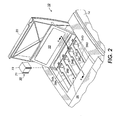
- the top surface of the housing includes a hinged top cover 20 that opens to reveal the ink feed system, as shown in Figures 2 and 3.
- the ink access cover 20 is attached to an ink load linkage element 22 so that when the printer ink access cover 20 is raised, the ink load linkage 22 slides and pivots to an ink load position.
- the interaction of the ink access cover and the ink load linkage element is described in United States Patent No. 5,861,903 for an Ink Feed System, issued January 19, 1999 to Crawford et al., though with some differences noted below.
- opening the ink access cover 20 reveals a key plate 26 having keyed openings 24.
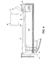
- Each keyed opening 24A, 24B, 24C, 24D provides access to an insertion end of one of several individual feed channels 28A, 28B, 28C, 28D of the solid ink feed system (see Figures 2, 3, and 4).
- each feed channel 28 is a longitudinal feed channel designed to deliver ink sticks 30 of a particular color to a corresponding melt plate 32.
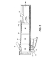
- the third feed channel 28C is shown in Figures 4 and 5, all the feed channels are identical for purposes of the following description.
- Each feed channel in the particular embodiment illustrated includes a push block 34 driven by a driving force or element, such as a constant force spring 36, to push the individual ink sticks 30 along the length of the longitudinal feed channel 28 toward the melt plates 32 that are at the melt end of each feed channel.
- Figure 5 shows the arrangement of elements when the ink access cover 20 ( Figures 1 and 2) is closed, and the ink load linkage element pulls the spring 36. The tension in the spring presses the push block 34 against the last ink stick (the ink stick closest to the insertion end of the feed channel).
- the feed channel has a longitudinal dimension from the insertion end to the melt end, and a lateral dimension, substantially perpendicular to the longitudinal dimension.
- the feed channel receives ink sticks inserted at the insertion end.
- the feed channel has sufficient longitudinal length that multiple ink sticks can be inserted into the feed channel, as seen in Figure 5.
- Each feed channel delivers ink sticks along the longitudinal length or feed direction of the channel to the corresponding melt plate at the melt end of the feed channel.
- the melt end of the feed channel is adjacent the melt plate.
- the melt plate melts the solid ink stick into a liquid form.
- the melted ink 31 drips through a gap 33 between the melt end of the feed channel and the melt plate, and into a liquid ink reservoir (not shown).
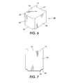
- Figure 6 shows an ink stick 30 formed of an ink stick body.
- the ink stick body may be substantially rectangular in shape, although those familiar with the art will recognize that other shapes can also be used.
- the ink stick body may be formed by pour molding, compression molding, or other appropriate techniques.
- Figure 6 shows one particular embodiment of an ink stick incorporating an alignment feature for enhancing the ability of ink sticks to maintain their proper alignment relative to one another in the feed channel of the solid ink feed system of the printer.
- the ink stick is illustrated without the key shapes on the lateral sides that correspond to the key plate openings 24 through the key plate 26, to simplify the illustration.
- the particular embodiment shown includes a substantially rectangular ink stick body that has a bottom, represented by a general bottom surface 52, and a top, represented by a general top surface 54, which may be substantially parallel to the bottom surface.
- a pair of general lateral side extremities or side surfaces 56 connect the bottom surface 52 and the top surface 54.
- the surfaces of the ink stick body need not be flat, nor need they be parallel or perpendicular one another. However, these descriptions will aid the reader in visualizing, even though the surfaces may have three dimensional topography, or be angled with respect to one another.
- the lateral side surfaces 56 need not be planar.
- the lateral side surfaces can be stepped so that the lower portion of the ink stick body is narrower than the upper portion, or the upper portion is narrower than the lower portion.
- the lateral side surfaces 56 can be shaped to provide a keying function.
- the key shaped lateral side surfaces correspond to the lateral edges of the keyed openings in the key plate to provide a unique match between each keyed opening and the corresponding ink sticks intended for insertion through that keyed opening and into that feed channel.
- the ink stick additionally includes a first end surface 61 and a second end surface 62.
- the first and second end surfaces are substantially parallel to one another, and substantially perpendicular to both the top and bottom surfaces, and to the lateral side surfaces.
- those skilled in the art will recognize that the first and second end surfaces need not be necessarily parallel to one another.
- the first and second end surfaces 61, 62 have complementary non-planar shapes or contours that provide nesting shapes or nesting elements 71, 72. These contours of the end surfaces 61, 62 may be defined by a plurality of straight lines connecting the top surface and the bottom surface along each of the end surfaces of the ink stick body.
- the contour of the first end surface forms one or more protruding nesting elements 71 extending from the face of the first end surface.
- the illustrated embodiment includes a pair of matching and symmetrically placed nesting elements 71 on the lateral outer portions of the first end surface.
- the protruding nesting elements illustrated extend uniformly along the entire height of the first end surface.
- the protruding nesting elements 71 may be segmented along the height of the first end surface, or may extend along only a portion of the height of the first end surface.
- the second end surface has recessed nesting elements 72 that have shapes complementary to the shapes of the protruding nesting elements 71 on the first end surface.
- the protruding nesting elements 71 on the first end surface of one ink stick can then are capable of nesting into the recessed nesting elements 72 of the second end surface of an adjacent ink stick when the ink sticks abut one another, such as when the ink sticks are stacked in the feed channel 28.
- the recessed nesting elements 72 of the contour of the second end surface 62 of a first ink stick 30A nest with the protruding nesting elements 71 of the contour on the first end surface 61 of the second ink stick 30B.
- the lateral sides of the protruding nesting elements 71 and recessed nesting elements 72 closely match one another to limit movement of the ink sticks relative one another. By limiting movement of the ink sticks with respect to one another, the ink sticks do not become skewed with respect to each other, or with respect to the feed channel, as the ink sticks travel along the length of the feed channel of the solid ink feed system.
- the ink stick With the ink stick properly aligned with the feed channel, the ink stick meets the melt plate 32 normal to the melt plate surface. Proper alignment between the ink stick and the melt plate enhances even melting of the ink stick. Even melting reduces the formation of unmelted corner slivers at the trailing end of each ink stick. Such unmelted corner slivers may slip through the gap 70 between the melt plate and the end of the feed channel, potentially interfering with the proper functioning of certain portions of the printer (see Figures 4 and 5).
- Key element shapes (not shown) in the lateral side surfaces 56 of the ink stick body may tend to affect the orientation of the ink stick body as the ink stick moves along the feed channel.
- the interaction of the nesting elements 71, 72 of the contoured end surfaces 61, 62 of adjacent ink sticks 30 counteracts that tendency, and maintains the correct orientation of the ink stick in the feed channel.
- the nesting of the protruding nesting elements 71 and the recessed nesting elements 72 of adjacent ink sticks reduce the "steering" effect of the push block 34 acting on the trailing end surface of the ink stick in the feed channel 28.
- laterally offset pressure by the pusher block is of lesser concern, and maintaining a perfect lateral balance of the force exerted by the push block on the ink stick is less critical than with certain other designs. Alignment of the ink sticks as they move along the feed channel also avoids jamming of the ink sticks due to showing of the ink sticks in the feed channel.
- the ink sticks can be placed in the feed channel 28 with either the first end surface 61 as the leading end surface (meeting the melt plate 32 first), or the second end surface 62 as the leading end surface.
- the perimeter of the keyed openings 24 can be formed to match the protruding and recessed nesting elements 71, 72 of the ink sticks. So matching the keyed openings with the nesting elements provides ink stick orientation control to ensure the printer operator consistently inserts the ink sticks in the correct direction.
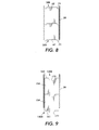
- ink sticks 130 incorporating contoured first and second end surfaces 161, 162 is shown.
- the ink sticks are shown inserted in the feed channel to illustrate the nesting of a single central recessed nesting element 172 on the second end surface 162 of one ink stick 130A nests with a protruding nesting element 171 on the first end surface 162 of the adjacent ink stick 130B.
- the contour of the front and rear end surfaces are each formed by a plurality of substantially parallel straight lines connecting the top surface and the bottom surface along the front and end surfaces respectively, so that the protruding and recessed nesting elements 171, 172 extend along the entire height of the end surfaces 161, 162.
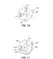
- Figure 10 illustrates an embodiment of the ink stick in which the protruding nesting element 571 does not extend along the entire height of the end surface 561 of the ink stick body.
- the protruding nesting element illustrated extends along the upper portion of the end surface 561.
- the protruding nesting element can extend along the lower portion of the end surface as well.
- the corresponding recessed nesting element 572 extends along at least the same portion of the height of the second end surface 562 as the protruding nesting element extends on the first end surface 561.
- the recessed nesting element can extend along a greater portion of the height of the second end surface than does the protruding nesting element.
- Figure 11 illustrates an embodiment of the ink stick in which the first and second end surfaces 461, 462 are each stepped or segmented.
- the protruding nesting element 471 extends along at least a segment 461A of the first end surface.
- a corresponding recessed nesting element 472 extends along a corresponding portion of a segment 462A of the second end surface.
- the end surfaces 461, 462 are each formed with an outermost portion above an inner portion.
- the protruding and recessed nesting elements are formed in the outermost segments of the first and second end surfaces. Numerous other arrangements providing segmented end surfaces for the ink stick can also be used.
- the protruding and recessed nesting elements need not both be in the outermost segments of both end surfaces.
- the protruding and recessed nesting elements can be formed in other segments of the end surfaces that mate with one another when the ink sticks are placed adjacent one another, as in an ink feed channel. More than one nesting element may be used on each ink stick.
- Figure 12 illustrates that the nesting elements may assume a variety of shapes.
- the shape of the protruding nesting element 271 on one end surface 261 substantially corresponds to and is the complement of the shape of the recessed nesting element 272 on the other end surface.
- Such complementary shaping maximizes the nesting capability, reducing movement of the ink sticks with respect to one another.
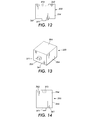
- FIG. 13 and 14 illustrates that the contours of the first and second end surfaces 361, 362 could be formed of curved lines extending from the top of the ink stick to the bottom of the ink stick.
- the protruding nesting element 371 from the first end surface 361 of the ink stick does not extend along the entire height of the first end surface from the top surface to the bottom surface.
- the recessed nesting element 372 in the second end surface 362 can, but need not, extend along the entire height of the second end surface.
- the recessed nesting element 372 is at least as large as the protruding nesting element 371 so that the recessed nesting element can received the protruding nesting element of an adjacent ink stick.
- the recessed nesting element 372 has a position relative to the side surfaces 356 and to the bottom surface 352 of the ink stick body that corresponds with the position of the protruding nesting element 371.
- the bottom surfaces of the adjacent ink sticks are substantially aligned, and the side surfaces of the adjacent ink sticks are also substantially aligned.
- the lateral dimensions of the recessed and projecting nesting elements are substantially identical, so that the interacting nesting elements block significant movement of the ink sticks relative to one another.
- Nesting elements could be subtle in size, so as to create frictional resistance to relative movement, rather than mechanical interlocking between adjacent ink sticks.
- the nesting element may be configured to simultaneously include one or more portions that are recessed, and one or more portions that protrude from the same end surface.
- the ink stick 30 is formed of two sections 31A, 31B that fit together at a joining line 35.
- the joining line is a substantially vertical cut through the ink stick body between the top and bottom surfaces 54, 52.
- the joining line of the illustrated embodiment intersects the lateral side surfaces 56 of the ink stick body, dividing the ink stick into longitudinal sections.
- the first longitudinal section 31A of the ink stick contains the first end surface 61 of the ink stick body, along with its protruding nesting element 71.
- the second longitudinal section 31 B of the ink stick contains the second end surface 62 of the ink stick body, along with the recessed nesting element 72.
- Each section of the ink stick has a perimeter that includes a joint perimeter segment.
- the joint perimeter segments of the two ink stick sections 31A, 31B have complementary shapes. When the two ink stick sections are brought together with the joint perimeter segments abutting, they form the joining line 35.
- the illustrated joining line 35 has a "puzzle cut" shape that provides a protrusion from one section of the ink stick that fits into a recess in the other section. The interaction of such a protrusion and recess helps to hold the two sections of the ink stick together as the printer operator inserts the assembled ink stick through the key plate opening 24 into the feed channel.
- the illustrated sections of the ink stick are substantially equal in size. However, other embodiments can have ink stick sections that are dissimilar in size. In addition, the ink stick can include more than two sections.
- the joining line can alternatively be between the top and bottom of the ink stick body, extend diagonally across the ink stick body, or longitudinally along the ink stick body, so that the joining line intersects the end surfaces 61, 62 of the ink stick body and divides the ink stick into lateral sections.
- the joining line is longitudinal in the ink stick body, dividing the ink stick body into lateral sections, more than one section of the ink stick body can contain some aspects of the protruding nesting element 71, and more than one section of the ink stick body can contain some aspects of the recessed nesting element 72.
- one or more sections of the ink stick body can contain at least portions of both the protruding nesting element 71 and the recessed nesting element 72.
Landscapes
- Ink Jet (AREA)
- Particle Formation And Scattering Control In Inkjet Printers (AREA)
- Ink Jet Recording Methods And Recording Media Thereof (AREA)
Applications Claiming Priority (2)
| Application Number | Priority Date | Filing Date | Title |
|---|---|---|---|
| US135089 | 2002-04-29 | ||
| US10/135,089 US6755517B2 (en) | 2002-04-29 | 2002-04-29 | Alignment feature for solid ink stick |
Publications (2)
| Publication Number | Publication Date |
|---|---|
| EP1359014A1 true EP1359014A1 (de) | 2003-11-05 |
| EP1359014B1 EP1359014B1 (de) | 2005-11-30 |
Family
ID=29215642
Family Applications (1)
| Application Number | Title | Priority Date | Filing Date |
|---|---|---|---|
| EP03008878A Expired - Lifetime EP1359014B1 (de) | 2002-04-29 | 2003-04-29 | Ausrichtvorrichtung für feste Tintenstifte |
Country Status (5)
| Country | Link |
|---|---|
| US (1) | US6755517B2 (de) |
| EP (1) | EP1359014B1 (de) |
| JP (1) | JP4274847B2 (de) |
| BR (1) | BR0301264B1 (de) |
| DE (1) | DE60302489T2 (de) |
Cited By (19)
| Publication number | Priority date | Publication date | Assignee | Title |
|---|---|---|---|---|
| EP1731315A1 (de) * | 2005-06-09 | 2006-12-13 | Xerox Corporation | Bestimmung des Tintenverbrauchs |
| EP1878578A1 (de) | 2006-07-12 | 2008-01-16 | Xerox Corporation | Tintenstift |
| EP1920936A1 (de) | 2006-11-07 | 2008-05-14 | Xerox Corporation | Einwegkompatibilitätsverschlüsselung für feste Tintenstifte |
| EP1967370A2 (de) | 2007-03-09 | 2008-09-10 | Xerox Corporation | Ineinandergreifender Tintenstift mit Mehrfachposition |
| EP1967368A2 (de) | 2007-03-09 | 2008-09-10 | Xerox Corporation | Fester Tintenstift mit umkehrbarem Schlüssel und ineinander greifenden Funktionen |
| EP1970200A2 (de) | 2007-03-12 | 2008-09-17 | Xerox Corporation | Festtintenstift mit abgeschrägter Fläche |
| US7517072B2 (en) | 2006-06-23 | 2009-04-14 | Xerox Corporation | Solid ink stick with enhanced differentiation |
| US7537326B2 (en) | 2006-06-23 | 2009-05-26 | Xerox Corporation | Solid ink stick with coded sensor feature |
| US7553008B2 (en) | 2006-06-23 | 2009-06-30 | Xerox Corporation | Ink loader for interfacing with solid ink sticks |
| CN101508205A (zh) * | 2008-02-15 | 2009-08-19 | 施乐公司 | 带有验证标记的固体墨块及其制造方法 |
| CN101092086B (zh) * | 2006-06-23 | 2010-06-02 | 施乐公司 | 带有接口元件的固体墨棒 |
| US7780284B2 (en) | 2007-03-09 | 2010-08-24 | Xerox Corporation | Digital solid ink stick identification and recognition |
| US7780283B2 (en) | 2006-11-07 | 2010-08-24 | Xerox Corporation | Independent keying and guidance for solid ink sticks |
| US7819513B2 (en) | 2007-03-09 | 2010-10-26 | Xerox Corporation | Solid ink stick with multiple axis interlocking |
| US7854501B2 (en) | 2006-11-07 | 2010-12-21 | Xerox Corporation | Common side insertion keying for phase change ink sticks |
| US7891792B2 (en) | 2007-11-06 | 2011-02-22 | Xerox Corporation | Solid ink stick with transition indicating region |
| US8007095B2 (en) | 2006-06-22 | 2011-08-30 | Xerox Corporation | Apparatus for reading markings on a solid ink stick |
| EP1935650A3 (de) * | 2006-12-22 | 2013-06-19 | Xerox Corporation | System zum Laden von zur Verhinderung einer seitlichen Schräglage konfigurierten Tintenstiften |
| CN101486274B (zh) * | 2008-01-18 | 2017-03-01 | 施乐公司 | 固态墨棒的视觉识别 |
Families Citing this family (37)
| Publication number | Priority date | Publication date | Assignee | Title |
|---|---|---|---|---|
| US6857732B2 (en) * | 2002-04-29 | 2005-02-22 | Xerox Corporation | Visible identification of solid ink stick |
| US6722764B2 (en) * | 2002-04-29 | 2004-04-20 | Xerox Corporation | Feed guidance and identification for ink stick |
| US6874880B2 (en) * | 2002-04-29 | 2005-04-05 | Xerox Corporation | Solid ink stick with identifiable shape |
| USD537872S1 (en) * | 2004-11-05 | 2007-03-06 | Xerox Corporation | Ink stick for phase change ink jet printer |
| USD529085S1 (en) * | 2004-11-05 | 2006-09-26 | Xerox Corporation | Ink stick for phase change ink jet printer |
| USD528159S1 (en) * | 2004-11-05 | 2006-09-12 | Xerox Corporation | Ink stick for phase change ink jet printer |
| US7503648B2 (en) * | 2005-06-09 | 2009-03-17 | Xerox Corporation | Ink consumption determination |
| US7425061B2 (en) * | 2005-06-09 | 2008-09-16 | Xerox Corporation | Ink consumption determination |
| US7591550B2 (en) * | 2005-06-09 | 2009-09-22 | Xerox Corporation | Ink consumption determination |
| US7753509B2 (en) * | 2006-08-14 | 2010-07-13 | Xerox Corporation | Segmented ink stick |
| US7651210B2 (en) * | 2006-11-21 | 2010-01-26 | Xerox Corporation | Transport system for solid ink for cooperation with melt head in a printer |
| US7976144B2 (en) * | 2006-11-21 | 2011-07-12 | Xerox Corporation | System and method for delivering solid ink sticks to a melting device through a non-linear guide |
| US7798624B2 (en) * | 2006-11-21 | 2010-09-21 | Xerox Corporation | Transport system for solid ink in a printer |
| US7794072B2 (en) * | 2006-11-21 | 2010-09-14 | Xerox Corporation | Guide for printer solid ink transport and method |
| US7883195B2 (en) * | 2006-11-21 | 2011-02-08 | Xerox Corporation | Solid ink stick features for printer ink transport and method |
| US7726797B2 (en) | 2006-11-28 | 2010-06-01 | Xerox Corporation | Intermediate side slot vertical ink constraint with offset support |
| US7753511B2 (en) * | 2006-11-28 | 2010-07-13 | Xerox Corporation | Lateral anti-skewing solution for solid ink |
| US7762655B2 (en) * | 2006-12-11 | 2010-07-27 | Xerox Corporation | Printer ink delivery system |
| US7878636B2 (en) * | 2006-12-12 | 2011-02-01 | Xerox Corporation | Solid ink stick chute for printer solid ink transport with mating solid ink stick chute |
| US7726798B2 (en) | 2006-12-15 | 2010-06-01 | Xerox Corporation | Printer solid ink transport and method |
| US7798626B2 (en) * | 2007-02-28 | 2010-09-21 | Xerox Corporation | System for loading and feeding solid ink sticks to an ink melter in a phase change ink printer |
| US7909445B2 (en) * | 2007-09-11 | 2011-03-22 | Xerox Corporation | Solid ink stick delivery system with static constraints, strategic barriers and breakage controls |
| US7824027B2 (en) * | 2007-09-11 | 2010-11-02 | Xerox Corporation | Solid ink stick with anti jam edge bevel |
| US8016403B2 (en) * | 2007-10-03 | 2011-09-13 | Xerox Corporation | Solid ink stick with visual orientation indicator |
| US7976118B2 (en) | 2007-10-22 | 2011-07-12 | Xerox Corporation | Transport system for providing a continuous supply of solid ink to a melting assembly in a printer |
| US7883196B2 (en) | 2007-12-21 | 2011-02-08 | Xerox Corporation | System for delivering solid ink through a feed channel having non-linear sections |
| US7942515B2 (en) * | 2007-12-21 | 2011-05-17 | Xerox Corporation | Solid ink stick having a feed drive coupler |
| US7887173B2 (en) | 2008-01-18 | 2011-02-15 | Xerox Corporation | Transport system having multiple moving forces for solid ink delivery in a printer |
| US8096647B2 (en) * | 2008-09-22 | 2012-01-17 | Xerox Corporation | Solid ink sticks having a verification interlock for verifying position of a solid ink stick before identifying the ink stick |
| US8052265B2 (en) * | 2008-09-22 | 2011-11-08 | Xerox Corporation | System and method for verifying position of an object before identifying the object |
| US8240830B2 (en) | 2010-03-10 | 2012-08-14 | Xerox Corporation | No spill, feed controlled removable container for delivering pelletized substances |
| US8366255B2 (en) | 2010-06-02 | 2013-02-05 | Xerox Corporation | Solid ink stick with retrieval feature |
| US8317308B2 (en) | 2010-07-14 | 2012-11-27 | Xerox Corporation | Solid ink stick with motion control inset |
| US8646892B2 (en) | 2011-12-22 | 2014-02-11 | Xerox Corporation | Solid ink stick delivery apparatus using a lead screw drive |
| US8814336B2 (en) | 2011-12-22 | 2014-08-26 | Xerox Corporation | Solid ink stick configuration |
| US8727478B2 (en) | 2012-10-17 | 2014-05-20 | Xerox Corporation | Ink loader having optical sensors to identify solid ink sticks |
| US8777386B2 (en) | 2012-10-17 | 2014-07-15 | Xerox Corporation | Solid ink stick having identical identifying features on a plurality of edges |
Citations (4)
| Publication number | Priority date | Publication date | Assignee | Title |
|---|---|---|---|---|
| EP0703085A2 (de) * | 1994-09-20 | 1996-03-27 | Tektronix, Inc. | Fester Tintenstift |
| EP0820872A2 (de) * | 1996-07-24 | 1998-01-28 | Brother Kogyo Kabushiki Kaisha | Tintentablette |
| US5734402A (en) * | 1996-03-07 | 1998-03-31 | Tekronix, Inc. | Solid ink stick feed system |
| US5861903A (en) * | 1996-03-07 | 1999-01-19 | Tektronix, Inc. | Ink feed system |
Family Cites Families (5)
| Publication number | Priority date | Publication date | Assignee | Title |
|---|---|---|---|---|
| US5455604A (en) | 1991-04-29 | 1995-10-03 | Tektronix, Inc. | Ink jet printer architecture and method |
| US5805191A (en) | 1992-11-25 | 1998-09-08 | Tektronix, Inc. | Intermediate transfer surface application system |
| USD380771S (en) | 1995-01-20 | 1997-07-08 | Tektronix, Inc. | Solid ink stick for a color printer |
| USD392651S (en) | 1996-07-22 | 1998-03-24 | Brother Kogyo Kabushiki Kaisha | Solid ink |
| USD416936S (en) * | 1997-03-10 | 1999-11-23 | Tektronix, Inc. | Solid ink stick for a color printer |
-
2002
- 2002-04-29 US US10/135,089 patent/US6755517B2/en not_active Expired - Lifetime
-
2003
- 2003-04-28 BR BRPI0301264-6A patent/BR0301264B1/pt not_active IP Right Cessation
- 2003-04-29 DE DE60302489T patent/DE60302489T2/de not_active Expired - Lifetime
- 2003-04-29 EP EP03008878A patent/EP1359014B1/de not_active Expired - Lifetime
- 2003-04-30 JP JP2003124658A patent/JP4274847B2/ja not_active Expired - Fee Related
Patent Citations (4)
| Publication number | Priority date | Publication date | Assignee | Title |
|---|---|---|---|---|
| EP0703085A2 (de) * | 1994-09-20 | 1996-03-27 | Tektronix, Inc. | Fester Tintenstift |
| US5734402A (en) * | 1996-03-07 | 1998-03-31 | Tekronix, Inc. | Solid ink stick feed system |
| US5861903A (en) * | 1996-03-07 | 1999-01-19 | Tektronix, Inc. | Ink feed system |
| EP0820872A2 (de) * | 1996-07-24 | 1998-01-28 | Brother Kogyo Kabushiki Kaisha | Tintentablette |
Cited By (40)
| Publication number | Priority date | Publication date | Assignee | Title |
|---|---|---|---|---|
| US7458669B2 (en) | 2005-06-09 | 2008-12-02 | Xerox Corporation | Ink consumption determination |
| EP1731315A1 (de) * | 2005-06-09 | 2006-12-13 | Xerox Corporation | Bestimmung des Tintenverbrauchs |
| US8007095B2 (en) | 2006-06-22 | 2011-08-30 | Xerox Corporation | Apparatus for reading markings on a solid ink stick |
| US7553008B2 (en) | 2006-06-23 | 2009-06-30 | Xerox Corporation | Ink loader for interfacing with solid ink sticks |
| US7537326B2 (en) | 2006-06-23 | 2009-05-26 | Xerox Corporation | Solid ink stick with coded sensor feature |
| US8366256B2 (en) | 2006-06-23 | 2013-02-05 | Xerox Corporation | Solid ink stick with interface element |
| CN101092086B (zh) * | 2006-06-23 | 2010-06-02 | 施乐公司 | 带有接口元件的固体墨棒 |
| US7857439B2 (en) | 2006-06-23 | 2010-12-28 | Xerox Corporation | Solid ink stick with interface element |
| US7517072B2 (en) | 2006-06-23 | 2009-04-14 | Xerox Corporation | Solid ink stick with enhanced differentiation |
| EP1878578A1 (de) | 2006-07-12 | 2008-01-16 | Xerox Corporation | Tintenstift |
| US8167418B2 (en) | 2006-07-12 | 2012-05-01 | Xerox Corporaiton | Method of feeding solid ink sticks into an ink loader of a phase change ink printer |
| CN101104337B (zh) * | 2006-07-12 | 2012-07-11 | 施乐公司 | 具有可靠编码数据的固体墨棒 |
| US7648232B2 (en) | 2006-07-12 | 2010-01-19 | Xerox Corporation | Solid ink stick with reliably encoded data |
| EP1920936A1 (de) | 2006-11-07 | 2008-05-14 | Xerox Corporation | Einwegkompatibilitätsverschlüsselung für feste Tintenstifte |
| US7810918B2 (en) | 2006-11-07 | 2010-10-12 | Xerox Corporation | One way compatibility keying for solid ink sticks |
| KR101386492B1 (ko) | 2006-11-07 | 2014-04-17 | 제록스 코포레이션 | 고체 잉크 스틱들을 위한 일 방향 호환성 키잉 |
| US7854501B2 (en) | 2006-11-07 | 2010-12-21 | Xerox Corporation | Common side insertion keying for phase change ink sticks |
| US7780283B2 (en) | 2006-11-07 | 2010-08-24 | Xerox Corporation | Independent keying and guidance for solid ink sticks |
| EP1935650A3 (de) * | 2006-12-22 | 2013-06-19 | Xerox Corporation | System zum Laden von zur Verhinderung einer seitlichen Schräglage konfigurierten Tintenstiften |
| US8075119B2 (en) | 2007-03-09 | 2011-12-13 | Xerox Corporation | Method for feeding solid ink stick with multiple interlocking axis in a solid ink printer |
| EP1967370A3 (de) * | 2007-03-09 | 2009-04-22 | Xerox Corporation | Ineinandergreifender Tintenstift mit Mehrfachposition |
| US7798627B2 (en) | 2007-03-09 | 2010-09-21 | Xerox Corporation | Multi-position interlocking ink stick |
| US7819513B2 (en) | 2007-03-09 | 2010-10-26 | Xerox Corporation | Solid ink stick with multiple axis interlocking |
| EP1967370A2 (de) | 2007-03-09 | 2008-09-10 | Xerox Corporation | Ineinandergreifender Tintenstift mit Mehrfachposition |
| EP1967368A2 (de) | 2007-03-09 | 2008-09-10 | Xerox Corporation | Fester Tintenstift mit umkehrbarem Schlüssel und ineinander greifenden Funktionen |
| US7780284B2 (en) | 2007-03-09 | 2010-08-24 | Xerox Corporation | Digital solid ink stick identification and recognition |
| EP1967368A3 (de) * | 2007-03-09 | 2009-03-04 | Xerox Corporation | Fester Tintenstift mit umkehrbarem Schlüssel und ineinander greifenden Funktionen |
| US7878641B2 (en) | 2007-03-09 | 2011-02-01 | Xerox Corporation | Solid ink stick with reversible keying and interlocking features |
| CN101259794B (zh) * | 2007-03-09 | 2012-03-21 | 施乐公司 | 具有可逆键合和互锁结构的固体墨棒 |
| US7802880B2 (en) | 2007-03-12 | 2010-09-28 | Xerox Corporation | Solid ink stick with canted surface |
| EP1970200A3 (de) * | 2007-03-12 | 2009-04-22 | Xerox Corporation | Festtintenstift mit abgeschrägter Fläche |
| CN101264693B (zh) * | 2007-03-12 | 2012-09-19 | 施乐公司 | 具有倾斜表面的固体墨棒、墨棒组以及供应墨棒的方法 |
| EP1970200A2 (de) | 2007-03-12 | 2008-09-17 | Xerox Corporation | Festtintenstift mit abgeschrägter Fläche |
| US7891792B2 (en) | 2007-11-06 | 2011-02-22 | Xerox Corporation | Solid ink stick with transition indicating region |
| CN101486274B (zh) * | 2008-01-18 | 2017-03-01 | 施乐公司 | 固态墨棒的视觉识别 |
| CN101508205A (zh) * | 2008-02-15 | 2009-08-19 | 施乐公司 | 带有验证标记的固体墨块及其制造方法 |
| EP2090440A1 (de) | 2008-02-15 | 2009-08-19 | Xerox Corporation | Tuschestab mit fester Tinte und Kennungsmarkierung |
| CN101508205B (zh) * | 2008-02-15 | 2013-01-02 | 施乐公司 | 带有验证标记的固体墨块及其制造方法 |
| US7837313B2 (en) | 2008-02-15 | 2010-11-23 | Xerox Corporation | Method of reconfiguring ink sticks |
| US7837317B2 (en) | 2008-02-15 | 2010-11-23 | Xerox Corporation | Solid ink stick with witness mark |
Also Published As
| Publication number | Publication date |
|---|---|
| US6755517B2 (en) | 2004-06-29 |
| JP2004001503A (ja) | 2004-01-08 |
| EP1359014B1 (de) | 2005-11-30 |
| US20030202078A1 (en) | 2003-10-30 |
| BR0301264B1 (pt) | 2012-05-02 |
| DE60302489D1 (de) | 2006-01-05 |
| BR0301264A (pt) | 2004-08-17 |
| DE60302489T2 (de) | 2006-06-01 |
| JP4274847B2 (ja) | 2009-06-10 |
Similar Documents
| Publication | Publication Date | Title |
|---|---|---|
| EP1359014B1 (de) | Ausrichtvorrichtung für feste Tintenstifte | |
| JP2003312015A (ja) | 多部分固体インクスティック | |
| EP1366909B1 (de) | Kodierungsmerkmal für festen Tintenstift | |
| EP1359020B1 (de) | Fester Tintenstift mit der Form eines numerischen Zeichens | |
| JP4308567B2 (ja) | 識別可能な固体インクスティック | |
| EP1359024B1 (de) | Sichtbare Erkennungselemente auf festen Tintenstiften | |
| EP1359016B1 (de) | Führungseinrichtung zur Zufuhr von festen Tintenstiften | |
| EP1359019B1 (de) | Kodierter Zuführungskanal zur Zufuhr von festen Tintenstiften | |
| EP1359022B1 (de) | Führungseinrichtung zur Zufuhr von festen Tintenstiften | |
| EP1359021A1 (de) | Führungseinrichtung zur Zufuhr von festen Tintenstiften | |
| EP1359015A1 (de) | Fester Tintenstift mit effizientem Länge-Breite-Verhältnis | |
| EP1369243A1 (de) | Kanalführung für Festtintenstiftzufuhr | |
| JP4966892B2 (ja) | 傾斜面を備える固体インクスティック | |
| EP1359023A1 (de) | Vielsegmentierte Kodierung zur Zufuhr von festen Tintenstiften | |
| KR101565763B1 (ko) | 상변화 잉크 이미징 디바이스에서 사용하기 위한 잉크 스틱 및 잉크 스틱 세트 | |
| US7722177B2 (en) | System for loading ink sticks configured for lateral anti-skewing | |
| US7942514B2 (en) | Keying elements for solid ink loader |
Legal Events
| Date | Code | Title | Description |
|---|---|---|---|
| PUAI | Public reference made under article 153(3) epc to a published international application that has entered the european phase |
Free format text: ORIGINAL CODE: 0009012 |
|
| AK | Designated contracting states |
Kind code of ref document: A1 Designated state(s): AT BE BG CH CY CZ DE DK EE ES FI FR GB GR HU IE IT LI LU MC NL PT RO SE SI SK TR |
|
| AX | Request for extension of the european patent |
Extension state: AL LT LV MK |
|
| 17P | Request for examination filed |
Effective date: 20040506 |
|
| AKX | Designation fees paid |
Designated state(s): DE FR GB |
|
| 17Q | First examination report despatched |
Effective date: 20041015 |
|
| GRAP | Despatch of communication of intention to grant a patent |
Free format text: ORIGINAL CODE: EPIDOSNIGR1 |
|
| GRAS | Grant fee paid |
Free format text: ORIGINAL CODE: EPIDOSNIGR3 |
|
| GRAA | (expected) grant |
Free format text: ORIGINAL CODE: 0009210 |
|
| AK | Designated contracting states |
Kind code of ref document: B1 Designated state(s): DE FR GB |
|
| REG | Reference to a national code |
Ref country code: GB Ref legal event code: FG4D |
|
| REF | Corresponds to: |
Ref document number: 60302489 Country of ref document: DE Date of ref document: 20060105 Kind code of ref document: P |
|
| ET | Fr: translation filed | ||
| PLBE | No opposition filed within time limit |
Free format text: ORIGINAL CODE: 0009261 |
|
| STAA | Information on the status of an ep patent application or granted ep patent |
Free format text: STATUS: NO OPPOSITION FILED WITHIN TIME LIMIT |
|
| 26N | No opposition filed |
Effective date: 20060831 |
|
| REG | Reference to a national code |
Ref country code: FR Ref legal event code: PLFP Year of fee payment: 14 |
|
| REG | Reference to a national code |
Ref country code: FR Ref legal event code: PLFP Year of fee payment: 15 |
|
| PGFP | Annual fee paid to national office [announced via postgrant information from national office to epo] |
Ref country code: FR Payment date: 20170322 Year of fee payment: 15 |
|
| PGFP | Annual fee paid to national office [announced via postgrant information from national office to epo] |
Ref country code: GB Payment date: 20170324 Year of fee payment: 15 |
|
| PGFP | Annual fee paid to national office [announced via postgrant information from national office to epo] |
Ref country code: DE Payment date: 20170321 Year of fee payment: 15 |
|
| REG | Reference to a national code |
Ref country code: DE Ref legal event code: R119 Ref document number: 60302489 Country of ref document: DE |
|
| GBPC | Gb: european patent ceased through non-payment of renewal fee |
Effective date: 20180429 |
|
| PG25 | Lapsed in a contracting state [announced via postgrant information from national office to epo] |
Ref country code: DE Free format text: LAPSE BECAUSE OF NON-PAYMENT OF DUE FEES Effective date: 20181101 |
|
| PG25 | Lapsed in a contracting state [announced via postgrant information from national office to epo] |
Ref country code: GB Free format text: LAPSE BECAUSE OF NON-PAYMENT OF DUE FEES Effective date: 20180429 |
|
| PG25 | Lapsed in a contracting state [announced via postgrant information from national office to epo] |
Ref country code: FR Free format text: LAPSE BECAUSE OF NON-PAYMENT OF DUE FEES Effective date: 20180430 |