EP1359016B1 - Guide pour l'alimentation de bâtons d'encre solide - Google Patents
Guide pour l'alimentation de bâtons d'encre solide Download PDFInfo
- Publication number
- EP1359016B1 EP1359016B1 EP03008880A EP03008880A EP1359016B1 EP 1359016 B1 EP1359016 B1 EP 1359016B1 EP 03008880 A EP03008880 A EP 03008880A EP 03008880 A EP03008880 A EP 03008880A EP 1359016 B1 EP1359016 B1 EP 1359016B1
- Authority
- EP
- European Patent Office
- Prior art keywords
- ink stick
- ink
- feed channel
- guide element
- feed
- Prior art date
- Legal status (The legal status is an assumption and is not a legal conclusion. Google has not performed a legal analysis and makes no representation as to the accuracy of the status listed.)
- Expired - Lifetime
Links
- 239000007787 solid Substances 0.000 title claims description 29
- 230000005484 gravity Effects 0.000 claims description 14
- 238000000034 method Methods 0.000 claims description 10
- 230000008859 change Effects 0.000 claims description 9
- 230000000284 resting effect Effects 0.000 claims description 4
- 239000000155 melt Substances 0.000 description 18
- 238000003780 insertion Methods 0.000 description 8
- 230000037431 insertion Effects 0.000 description 8
- 230000000875 corresponding effect Effects 0.000 description 7
- 239000007788 liquid Substances 0.000 description 6
- 230000007246 mechanism Effects 0.000 description 4
- 239000008188 pellet Substances 0.000 description 3
- 239000003086 colorant Substances 0.000 description 2
- 230000000694 effects Effects 0.000 description 2
- 239000012943 hotmelt Substances 0.000 description 2
- 230000003993 interaction Effects 0.000 description 2
- 239000000463 material Substances 0.000 description 2
- 238000002844 melting Methods 0.000 description 2
- 230000008018 melting Effects 0.000 description 2
- 238000007639 printing Methods 0.000 description 2
- 230000015572 biosynthetic process Effects 0.000 description 1
- 238000000748 compression moulding Methods 0.000 description 1
- 230000001276 controlling effect Effects 0.000 description 1
- 230000002079 cooperative effect Effects 0.000 description 1
- 230000001419 dependent effect Effects 0.000 description 1
- 238000007641 inkjet printing Methods 0.000 description 1
- 238000004519 manufacturing process Methods 0.000 description 1
- 238000012986 modification Methods 0.000 description 1
- 230000004048 modification Effects 0.000 description 1
- 238000000465 moulding Methods 0.000 description 1
- 229920006395 saturated elastomer Polymers 0.000 description 1
- 238000012876 topography Methods 0.000 description 1
Images


Classifications
-
- B—PERFORMING OPERATIONS; TRANSPORTING
- B41—PRINTING; LINING MACHINES; TYPEWRITERS; STAMPS
- B41J—TYPEWRITERS; SELECTIVE PRINTING MECHANISMS, i.e. MECHANISMS PRINTING OTHERWISE THAN FROM A FORME; CORRECTION OF TYPOGRAPHICAL ERRORS
- B41J2/00—Typewriters or selective printing mechanisms characterised by the printing or marking process for which they are designed
- B41J2/005—Typewriters or selective printing mechanisms characterised by the printing or marking process for which they are designed characterised by bringing liquid or particles selectively into contact with a printing material
- B41J2/01—Ink jet
- B41J2/17—Ink jet characterised by ink handling
- B41J2/175—Ink supply systems ; Circuit parts therefor
- B41J2/17593—Supplying ink in a solid state
Definitions
- the present invention relates generally to ink printers, the ink used in such ink printers, and the apparatus and method for feeding the ink into the printer.
- Solid ink or phase change ink printers conventionally receive ink in a solid form, either as pellets or as ink sticks.
- a feed mechanism delivers the solid ink to a heater assembly, where the ink is melted into a liquid state for jetting onto a receiving medium.
- Solid ink or phase change ink printers conventionally receive ink in a solid form and convert the ink to a liquid form for jetting onto a receiving medium.
- the printer receives the solid ink either as pellets or as ink sticks in a feed chute. With solid ink sticks, the solid ink sticks are either gravity fed or spring loaded through the feed channel toward a heater plate. The heater plate melts the solid ink into its liquid form. In a printer that receives solid ink sticks, the sticks are gravity fed or spring loaded along a feed channel and pressed against a heater plate to melt the solid ink into its liquid form.
- United States Patent No. 5,734,402 for a Solid Ink Feed System, issued March 31, 1998 to Rousseau et al.; and United States Patent No. 5,861,903 for an Ink Feed System, issued January 19, 1999 to Crawford et al. describe exemplary systems for delivering solid ink sticks into a phase change ink printer.
- EP0820872-A2 describes an ink pellet formed of solid hot melt ink which is stored in an accommodating channel section of an ink supplying system relative to a tank section so as to provide a predetermined amount of hot melt ink to the tank section.
- the preambles of claims 1 and 2 are based on this document.
- This object is achieved by providing a method of loading an ink stick into a solid ink feed system according to claim 1 and an ink stick for use in a solid ink feed system according to claim 2.
- Figure 1 is a perspective view of a phase change printer with the printer top cover closed.
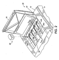
- Figure 2 is an enlarged partial top perspective view of the phase change printer with the ink access cover open, showing a solid ink stick in position to be loaded into a feed channel.
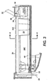
- Figure 3 is a side sectional view of a feed channel of a solid ink feed system taken along line 3 - 3 of Figure 2.
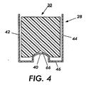
- Figure 4 is a simplified cross-sectional view of a feed channel taken along line 4 - 4 of Figure 3.
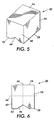
- Figure 5 is a perspective view of one embodiment of a solid ink stick.
- Figure 6 is an end elevational view of the ink stick of Figure 3.
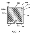
- Figure 7 is a simplified cross-sectional view of an alternate feed channel.
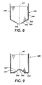
- Figure 8 is a simplified cross-sectional view of another alternate feed channel.
- Figure 9 is a simplified cross-sectional view of yet another alternate feed channel.
- Figure 10 is a simplified cross-sectional view of yet another alternate feed channel.
- Figure 1 shows a solid ink, or phase change, ink printer 10 that includes an outer housing having a top surface 12 and side surfaces 14.
- a user interface display such as a front panel display screen 16 displays information concerning the status of the printer, and user instructions.
- Buttons 18 or other control elements for controlling operation of the printer are adjacent the user interface window, or may be at other locations on the printer.
- An ink jet printing mechanism (not shown) is contained inside the housing. Such a printing mechanism is described in United States Patent No. 5,805,191, entitled Surface Application System, to Jones et al, and United States Patent No. 5,455,604, entitled Ink Jet Printer Architecture and Method, to Adams et al.
- An ink feed system delivers ink to the printing mechanism.
- the ink feed system is contained under the top surface of the printer housing.
- the top surface of the housing includes a hinged ink access cover 20 that opens as shown in Figure 2, to provide the user access to the ink feed system.
- the ink access cover 20 is attached to an ink load linkage element 22 so that when the printer ink access cover 20 is raised, the ink load linkage 22 slides and pivots to an ink load position.
- the interaction of the ink access cover and the ink load linkage element is described in United States Patent No. 5,861,903 for an Ink Feed System, issued January 19, 1999 to Crawford et al., though with some differences noted below.
- opening the ink access cover reveals a key plate 26 having keyed openings 24.
- Each keyed opening 24A, 24B, 24C, 24D provides access to an insertion end of one of several individual feed channels 28A, 28B, 28C, 28D of the solid ink feed system (see Figures 2 and 3).
- Each longitudinal feed channel 28 delivers ink sticks 30 of one particular color to a corresponding melt plate 32.
- Each feed channel has a longitudinal feed direction from the insertion end of the feed channel to the melt end of the feed channel.
- the melt end of the feed channel is adjacent the melt plate.
- the melt plate melts the solid ink stick into a liquid form.
- the melted ink drips through a gap 33 between the melt end of the feed channel and the melt plate, and into a liquid ink reservoir (not shown).
- the feed channels 28 have a longitudinal dimension from the insertion end to the melt end, and a lateral dimension, substantially perpendicular to the longitudinal dimension.
- Each feed channel in the particular embodiment illustrated includes a push block 34 driven by a driving force or element, such as a constant force spring 36, to push the individual ink sticks along the length of the longitudinal feed channel toward the melt plates 32 that are at the melt end of each feed channel.
- the tension of the constant force spring 36 drives the push block toward the melt end of the feed channel.
- the ink load linkage 22 is coupled to a yoke 38, which is attached to the constant force spring 36 mounted in the push block 34. The attachment to the ink load linkage 22 pulls the push block 34 toward the insertion end of the feed channel when the ink access cover is raised to reveal the key plate 26.
- a color printer typically uses four colors of ink (yellow, cyan, magenta, and black).
- Ink sticks 30 of each color are delivered through a corresponding individual one of the feed channels 28.
- the operator of the printer exercises cares to avoid inserting ink sticks of one color into a feed channel for a different color.
- Ink sticks may be so saturated with color dye that it may be difficult for a printer user to tell by color alone which color is which. Cyan, magenta, and black ink sticks in particular can be difficult to distinguish visually based on color appearance.
- the key plate 26 has keyed openings 24 to aid the printer user in ensuring that only ink sticks of the proper color are inserted into each feed channel.
- Each keyed opening 24 of the key plate has a unique shape.
- the ink sticks 30 of the color for that feed channel have a shape corresponding to the shape of the keyed opening.
- the keyed openings and corresponding ink stick shapes exclude from each ink feed channel ink sticks of all colors except the ink sticks of the proper color for that feed channel.
- the feed channel 28 is defined by lateral side walls 42, 44 that are substantially vertical, and a bottom 46.
- the transverse dimension is between the lateral side walls 42, 44.
- a longitudinal feed channel guide rail 40 is included in a lower portion of the feed channel, preferably near the bottom of the feed channel.
- This feed channel guide rail 40 is substantially centered in the lateral dimension in the feed channel, as shown in Figure 4, so that it is aligned with the central longitudinal axis of the feed channel.
- the guide rail 40 is designed to receive the bottom surface of an ink stick.
- the exemplary feed channel guide rail illustrated is approximately the shape of an inverted "V" with a truncated peak, so that the width of the feed channel guide rail 40 at its peak is substantially less than the width of the feed channel between the side walls 42, 44.
- FIG. 5 An exemplary solid ink stick 30 for use in the feed channel with the feed channel guide rail is illustrated in Figures 5 and 6.
- the ink stick is formed of an ink stick body having a bottom, represented by a general bottom surface 52, a top, represented by a general top surface 54, and at least two lateral sides 56.
- the ink stick is illustrated without the key shapes on the lateral sides that correspond to the key plate openings 24 through the key plate 26, to simplify the illustration.
- the surfaces of the ink stick body need not be flat, nor need they be parallel or perpendicular one another. However, these descriptions will aid the reader in visualizing, even though the surfaces may have three dimensional topography, or be angled with respect to one another.
- the bottom of the ink stick body is a bottom surface having lateral edges 58 at which the bottom surface 52 intersects the lateral side surfaces 56.
- the ink stick body may be formed in a substantially rectangular block in which the lateral side surfaces 56 are substantially parallel one another. Such a rectangular block form of the ink stick body also includes two end surfaces 60 that are substantially parallel to one another, and are substantially perpendicular to the side surfaces 56. Nevertheless, other shapes of the side and end surfaces are also possible, including curved surfaces.
- the side surfaces 56 may also be shaped with the key shapes to match the keyed openings 24 through the key plate 26.
- the lateral side surfaces can also be segmented or stepped, so that one portion of the ink stick body is narrower than another.
- the ink stick body may be formed by pour molding, compression molding, or other forming techniques.
- the ink stick body has a lateral center of gravity 63 between the lateral side surfaces 56 of the ink stick body, and a vertical center of gravity 63 between the top and bottom surfaces 52, 54. If the ink stick body has a substantially uniform weight density, the lateral center of gravity 63 is approximately midway between the lateral side surfaces 56 of the ink stick body. The lateral center of gravity 64 is identified in the ink stick body without the key shape elements that may be formed in the lateral side surfaces of the ink stick body.
- Guide means including a longitudinal ink stick guide element 66 is formed in the lower portion of the ink stick body for guiding the ink stick 30 along the feed channel guide rail 40 in the feed channel 28.
- the longitudinal guide element 66 is formed in the bottom surface 52 of the ink stick body, and extends along the entire length of the body between the end surfaces 60.
- the longitudinal guide element 66 is symmetrical about the lateral center of gravity 63 of the ink stick body.
- the bottom surface 52 of the ink stick body is formed in the shape of an inverted "V", with the peak approximately vertically aligned with the lateral center of gravity of the body to form the ink stick guide element 66.
- the peak of the inverted V forming the guide element is substantially midway between the lateral edges 58 of the bottom surface of the ink stick body.
- the corners and edges may have radii, and not be square. In addition, in certain circumstances, radiused edges will be desired.
- the slope of the "V" shape of the ink stick guide element 66 in the bottom surface of the ink stick body is substantially the same as the slope of the feed channel guide rail 40 in the ink feed channel.
- This common slope between the guide element surface 66 and the feed channel guide rail 40 allows a portion of the ink stick guide element to contact the feed channel guide rail to allow the feed channel guide rail to guide the ink stick along the feed channel, and help to hold the ink stick upright in the feed channel.
- the only contact between the bottom surface of the ink stick body and the longitudinal feed channel is the contact between the central guide element in the bottom surface of the ink stick body and the feed channel guide rail.
- the lateral side portions of the bottom surface of the ink stick body, adjacent the lateral edges 58 of the bottom surface 52 do not contact the bottom 46 of the feed channel 28. Such minimal contact between the bottom surface of the ink stick body and the feed channel guide rail minimizes the opportunity for chips or flakes of the ink material to interfere with the progress of the ink stick along the feed channel.
- the lateral dimension of the ink stick body between the side surfaces 56 is no wider than the lateral dimension of the ink stick feed channel 28 between the side walls 42, 44.
- the lateral dimension of the ink stick body between the side surfaces 56 is substantially the same as the lateral dimension of the ink stick feed channel 28 between the side walls 42, 44, or more specifically only fractionally smaller than the lateral dimension of the ink stick feed channel 28 between the side walls 42, 44.
- the ink stick body may have a longitudinal dimension (not including protruding insertion key or orientation elements) between the end surfaces 60 of between approximately 1.1 and 1.8 inches (28 - 46 mm), such as 1.5 inches (37 mm).
- the ink stick body may have a lateral dimension (not including protruding insertion key or orientation elements) between the lateral side surfaces 56 of between approximately 1.0 and 1.3 inches (25 - 33 mm), such as 1.3 inches (33 mm).
- the ink stick body may have a vertical dimension between the bottom and top surfaces 52, 54 of between approximately 1.0 and 1.5 inches (25 - 38 mm), such as 1.25 inches (32 mm).
- the lateral dimension of the ink stick feed channel 28 between the side walls 42, 44 may be approximately 0.004 to 0.08 inches (0.1 - 2.0 mm) wider than the lateral dimension of the ink stick body.
- the ink stick body 30 remains substantially upright and balanced with the central longitudinal guide element of the ink stick body resting on the feed channel guide rail of the feed channel.
- one of the upper lateral edges of the ink stick body formed by the intersection of the lateral side surfaces 56 with the top surface 54 may contact a side wall 42, 44 of the feed channel.
- substantially the only contact between the bottom surface of the ink stick body and the feed channel is the contact between the longitudinal guide element 66 formed in the bottom surface of the ink stick body, and the guide rail 40 in the feed channel. Minor contact between an upper portion of the lateral side surface 56 of the ink stick body and the side of the feed channel 42, 44 may also occur.
- the ink stick guide element 66 in the bottom surface of the ink stick body and the feed channel guide rail 40 in the feed channel cooperate to maintain the orientation of the ink stick as the ink stick progresses along the length of the feed channel from the insertion end to the melt end.
- the ink stick guide element 66 and the feed channel guide rail 40 forming the guide means keep the ink stick aligned with the feed channel.
- the ink stick body does not become skewed with respect to the feed channel. With the ink stick properly aligned with the feed channel, the ink stick meets the melt plate 32 normal to the melt plate surface. Proper alignment between the ink stick and the melt plate enhances even melting of the ink stick.
- Key element shapes in the lateral side surfaces 56 of the ink stick body may tend to affect the orientation of the ink stick body as the ink stick moves along the feed channel.
- the interaction of the guide element 66 and the guide rail 40 counteracts that tendency, and maintains the correct orientation of the ink stick in the feed channel.
- the cooperative action of the ink stick guide element 66 and the feed channel guide rail 40 also reduce the "steering" effect the push block 34 acting on the trailing end surface of the ink stick in the feed channel 28.
- laterally offset pressure by the push block 34 on the ink stick body is of lesser concern, and maintaining a perfect lateral balance of the force exerted by the push block on the ink stick is less critical than with certain other designs.
- the inverted "V" shape of the ink stick guide element 66 need not necessarily extend all of the way to the lateral edges 58 of the bottom surface of the ink stick body.
- the outer lateral portions of the bottom surface may be substantially flat, parallel to the top surface 54 of the ink stick body.
- Various alternative shapes for the bottom surface of the ink stick body can be implemented. Also, radius edges and corners can also be included in the ink stick body.
- Figure 7 illustrates an embodiment in which the slope of the feed channel guide rail 140 is substantially steeper than the slope of the ink stick guide element 166 of the ink stick 130.
- This embodiment provides particularly minimal contact between the bottom of the ink stick and the feed channel surfaces, minimizing the effects of friction between them.
- the side walls 142, 144 of the feed channel help to guide the ink stick along the feed channel, as the ink stick may tend to tilt to one side or the other of contact between the feed channel guide rail 140 and the ink stick guide element 166.
- the upper portions of the side walls 142, 144 of the feed channel form a second feed channel guide rail 148 that slidingly engage a second guide element 168 formed on the upper portion of the lateral side surfaces of the ink stick.
- the ink stick body embodiment shown in Figure 8 has a bottom surface 252 with an ink stick guide element 266 formed as a noninverted, or projecting, "V" shape.
- the bottom surface of the feed channel has a corresponding shape to form the feed channel guide rail 240.
- the feed channel guide rail 240 is formed as two angled channel segments that extend from the side walls 242, 244 toward the center of the feed channel.
- the angle of the feed channel guide rail 240 substantially matches the angle of the guide element 266.
- the feed channel guide rail 240 does not extend across the entire width of the feed channel, providing an opening 243 in the bottom of the feed channel.
- the bottom opening 243 allows chips and slivers of ink material that break off from the ink stick to fall away, so that they do not interfere with movement of the ink stick along the feed channel.
- the ink stick 330 shown in Figure 9 includes a guide element 266 formed as a concave shape in the bottom 352 of the ink stick body.
- the concave ink stick guide element 366 cooperates with the feed channel guide rail 340.
- the feed channel guide rail 340 and the ink stick guide element 366 have alignment guides 341, 367 to avoid a tendency of the ink stick to rotate about the feed channel guide rail 340 and tilt in the feed channel.
- the alignment guides illustrated are a longitudinal ridge 341 along the feed channel guide rail 340, and a corresponding longitudinal notch along the ink stick guide element 366.
- the guide element can also be formed of a convex shape in the bottom of the ink stick body.
- Figure 10 shown an ink stick with the outer portion of an ink stick bottom in contact with, and resting on, the feed channel support in the feed channel.
- the ink stick is guided in the lateral direction by a centrally located raised guide element in the feed channel.
- the majority of the bottom surface of the ink stick is not in contact with the bottom surface of the feed channel.
- the printer user provides an ink stick such as the ink stick shown in Figures 4 - 6, or the alternative embodiments shown in Figures 7 - 9.
- the user opens the printer cover 20, which in turn pivots and slides the ink load linkage 22, as seen in Figure 2.
- the user inserts the ink stick 30 through the keyed opening 24 in the key plate 26 and into the corresponding feed channel 28.
- the user inserts the ink stick so that the ink stick guide element 66 formed in the bottom surface of the ink stick body is aligned with the feed channel guide rail 40 in the feed system.
- the user places the ink stick body in the insertion end of the feed channel so that the ink stick guide element 66 rests on the feed channel guide rail 40. In this way, substantially the only contact between the bottom surface of the ink stick and the feed system is the contact between the guide element in the ink stick body and the feed channel guide rail of the feed channel.
- the user then closes the printer cover 20.
- the push block 34 pushes the ink stick along the feed channel 28 toward the melt plate 32, with the ink stick guide element 66 sliding along the feed channel guide rail 40 of the feed channel.
Landscapes
- Ink Jet (AREA)
- Particle Formation And Scattering Control In Inkjet Printers (AREA)
Claims (4)
- Procédé de chargement d'un bâton d'encre (30) dans un système d'alimentation en encre solide d'une imprimante jet d'encre à changement de phase (10), le procédé comprenant :la fourniture d'un bâton d'encre (30), dans lequel le bâton d'encre inclut :caractérisé en ce queune surface inférieure (52) ;un centre de gravité latéral (63) ; etun élément de guidage du bâton d'encre (66) sur la surface inférieure (52), aligné sur le centre de gravité latéral (63) ;l'alignement de l'élément de guidage du bâton d'encre (66) à l'aide d'un rail de guidage de voie d'alimentation (40) dans le système d'alimentation ;l'insertion du bâton d'encre (30) dans le système d'alimentation ; et
l'élément de guidage du bâton d'encre (66) repose sur le rail de guidage de voie d'alimentation (40) de sorte que le contact entre l'élément de guidage du bâton d'encre (66) et le rail de guidage de voie d'alimentation (40) est le seul contact entre la surface inférieure (52) du bâton d'encre (30) et le système d'alimentation. - Bâton d'encre (30) à utiliser dans un système d'alimentation en encre solide d'une imprimante jet d'encre à changement de phase (10), dans laquelle le système d'alimentation comprend une voie d'alimentation (28) comportant un rail de guidage de voie d'alimentation central (40), le bâton d'encre (30) comprenant :un corps de bâton d'encre comportant :caractérisé en ce queune surface inférieure (52) ;un centre de gravité latéral (63) ; etun élément de guidage du bâton d'encre (66) sur la surface inférieure (52)aligné sur le centre de gravité latéral (63) du corps de bâton d'encre ;
l'élément de guidage du bâton d'encre (66) peut auto-centrer le bâton d'encre dans la voie d'alimentation lorsque l'élément de guidage du bâton d'encre repose sur le rail de guidage de voie d'alimentation central (40), de sorte qu'un contact entre l'élément de guidage du bâton d'encre et le rail de guidage de voie d'alimentation est le seul contact entre la surface inférieure du bâton d'encre et le système d'alimentation. - Bâton d'encre selon la revendication 2, dans lequel le centre de gravité latéral (63) du corps de bâton d'encre est le centre de gravité latéral du corps de bâton d'encre ne comptant pas comme éléments clés formés dans le corps de bâton d'encre.
- Bâton d'encre selon la revendication 2 ou 3, dans lequel :la surface inférieure (52) du bâton d'encre (30) a une forme de « V » inversé qui constitue l'élément de guidage du bâton d'encre (66).
Applications Claiming Priority (2)
| Application Number | Priority Date | Filing Date | Title |
|---|---|---|---|
| US135077 | 2002-04-29 | ||
| US10/135,077 US6840613B2 (en) | 2002-04-29 | 2002-04-29 | Guide for solid ink stick feed |
Publications (2)
| Publication Number | Publication Date |
|---|---|
| EP1359016A1 EP1359016A1 (fr) | 2003-11-05 |
| EP1359016B1 true EP1359016B1 (fr) | 2006-12-13 |
Family
ID=29215639
Family Applications (1)
| Application Number | Title | Priority Date | Filing Date |
|---|---|---|---|
| EP03008880A Expired - Lifetime EP1359016B1 (fr) | 2002-04-29 | 2003-04-29 | Guide pour l'alimentation de bâtons d'encre solide |
Country Status (6)
| Country | Link |
|---|---|
| US (1) | US6840613B2 (fr) |
| EP (1) | EP1359016B1 (fr) |
| JP (1) | JP2003312021A (fr) |
| BR (1) | BR0301100B1 (fr) |
| CA (1) | CA2426170C (fr) |
| DE (1) | DE60310296T2 (fr) |
Families Citing this family (49)
| Publication number | Priority date | Publication date | Assignee | Title |
|---|---|---|---|---|
| US6722764B2 (en) * | 2002-04-29 | 2004-04-20 | Xerox Corporation | Feed guidance and identification for ink stick |
| US6840612B2 (en) * | 2002-04-29 | 2005-01-11 | Xerox Corporation | Guide for solid ink stick feed |
| US6739713B2 (en) | 2002-04-29 | 2004-05-25 | Xerox Corporation | Guide for solid ink stick feed |
| US20050151814A1 (en) * | 2004-01-12 | 2005-07-14 | Xerox Corporation | Guide for solid ink stick feed |
| US7296882B2 (en) | 2005-06-09 | 2007-11-20 | Xerox Corporation | Ink jet printer performance adjustment |
| US7874661B2 (en) * | 2006-06-22 | 2011-01-25 | Xerox Corporation | Solid ink stick with coded markings and method and apparatus for reading markings |
| US7553008B2 (en) | 2006-06-23 | 2009-06-30 | Xerox Corporation | Ink loader for interfacing with solid ink sticks |
| US7857439B2 (en) * | 2006-06-23 | 2010-12-28 | Xerox Corporation | Solid ink stick with interface element |
| US7517072B2 (en) | 2006-06-23 | 2009-04-14 | Xerox Corporation | Solid ink stick with enhanced differentiation |
| US7537326B2 (en) | 2006-06-23 | 2009-05-26 | Xerox Corporation | Solid ink stick with coded sensor feature |
| US7648232B2 (en) * | 2006-07-12 | 2010-01-19 | Xerox Corporation | Solid ink stick with reliably encoded data |
| US7631963B2 (en) * | 2006-08-01 | 2009-12-15 | Xerox Corporation | Method of forming solid ink stick with coded mark |
| US7682010B2 (en) * | 2006-10-11 | 2010-03-23 | Xerox Corporation | Solid ink stick with coating |
| US7753510B2 (en) * | 2006-10-11 | 2010-07-13 | Xerox Corporation | Solid ink composition with post-melt mixing |
| US7594716B2 (en) * | 2006-10-17 | 2009-09-29 | Xerox Corporation | Collapsible ink loader feed support |
| US7641327B2 (en) * | 2006-10-17 | 2010-01-05 | Xerox Corporation | Replaceable ink stick guides and supports |
| US7695126B2 (en) * | 2006-10-17 | 2010-04-13 | Xerox Corporation | Ink loader mechanism using an ink stick carrier |
| US7854501B2 (en) * | 2006-11-07 | 2010-12-21 | Xerox Corporation | Common side insertion keying for phase change ink sticks |
| US7780283B2 (en) * | 2006-11-07 | 2010-08-24 | Xerox Corporation | Independent keying and guidance for solid ink sticks |
| US7810918B2 (en) * | 2006-11-07 | 2010-10-12 | Xerox Corporation | One way compatibility keying for solid ink sticks |
| US7690775B2 (en) * | 2006-11-07 | 2010-04-06 | Xerox Corporation | Solid ink sticks with corner guides |
| US7794072B2 (en) * | 2006-11-21 | 2010-09-14 | Xerox Corporation | Guide for printer solid ink transport and method |
| US7883195B2 (en) * | 2006-11-21 | 2011-02-08 | Xerox Corporation | Solid ink stick features for printer ink transport and method |
| US7976144B2 (en) * | 2006-11-21 | 2011-07-12 | Xerox Corporation | System and method for delivering solid ink sticks to a melting device through a non-linear guide |
| US7798624B2 (en) * | 2006-11-21 | 2010-09-21 | Xerox Corporation | Transport system for solid ink in a printer |
| US7651210B2 (en) * | 2006-11-21 | 2010-01-26 | Xerox Corporation | Transport system for solid ink for cooperation with melt head in a printer |
| US7753511B2 (en) * | 2006-11-28 | 2010-07-13 | Xerox Corporation | Lateral anti-skewing solution for solid ink |
| US7726797B2 (en) * | 2006-11-28 | 2010-06-01 | Xerox Corporation | Intermediate side slot vertical ink constraint with offset support |
| US7762655B2 (en) * | 2006-12-11 | 2010-07-27 | Xerox Corporation | Printer ink delivery system |
| US7878636B2 (en) * | 2006-12-12 | 2011-02-01 | Xerox Corporation | Solid ink stick chute for printer solid ink transport with mating solid ink stick chute |
| US7726798B2 (en) | 2006-12-15 | 2010-06-01 | Xerox Corporation | Printer solid ink transport and method |
| US7722177B2 (en) * | 2006-12-22 | 2010-05-25 | Xerox Corporation | System for loading ink sticks configured for lateral anti-skewing |
| US7798626B2 (en) * | 2007-02-28 | 2010-09-21 | Xerox Corporation | System for loading and feeding solid ink sticks to an ink melter in a phase change ink printer |
| US7878641B2 (en) * | 2007-03-09 | 2011-02-01 | Xerox Corporation | Solid ink stick with reversible keying and interlocking features |
| US7798627B2 (en) * | 2007-03-09 | 2010-09-21 | Xerox Corporation | Multi-position interlocking ink stick |
| US7819513B2 (en) * | 2007-03-09 | 2010-10-26 | Xerox Corporation | Solid ink stick with multiple axis interlocking |
| US7780284B2 (en) * | 2007-03-09 | 2010-08-24 | Xerox Corporation | Digital solid ink stick identification and recognition |
| US7802880B2 (en) * | 2007-03-12 | 2010-09-28 | Xerox Corporation | Solid ink stick with canted surface |
| US7824027B2 (en) * | 2007-09-11 | 2010-11-02 | Xerox Corporation | Solid ink stick with anti jam edge bevel |
| US7909445B2 (en) * | 2007-09-11 | 2011-03-22 | Xerox Corporation | Solid ink stick delivery system with static constraints, strategic barriers and breakage controls |
| US7976118B2 (en) | 2007-10-22 | 2011-07-12 | Xerox Corporation | Transport system for providing a continuous supply of solid ink to a melting assembly in a printer |
| US7891792B2 (en) * | 2007-11-06 | 2011-02-22 | Xerox Corporation | Solid ink stick with transition indicating region |
| US7942515B2 (en) * | 2007-12-21 | 2011-05-17 | Xerox Corporation | Solid ink stick having a feed drive coupler |
| US7883196B2 (en) * | 2007-12-21 | 2011-02-08 | Xerox Corporation | System for delivering solid ink through a feed channel having non-linear sections |
| US7887173B2 (en) | 2008-01-18 | 2011-02-15 | Xerox Corporation | Transport system having multiple moving forces for solid ink delivery in a printer |
| US8240830B2 (en) | 2010-03-10 | 2012-08-14 | Xerox Corporation | No spill, feed controlled removable container for delivering pelletized substances |
| US8317308B2 (en) * | 2010-07-14 | 2012-11-27 | Xerox Corporation | Solid ink stick with motion control inset |
| US8646892B2 (en) | 2011-12-22 | 2014-02-11 | Xerox Corporation | Solid ink stick delivery apparatus using a lead screw drive |
| CN112339241B (zh) * | 2020-10-16 | 2022-05-31 | 界首市宏达塑业有限公司 | 一种塑料颗粒生产用挤塑机供料设备及其工作方法 |
Family Cites Families (8)
| Publication number | Priority date | Publication date | Assignee | Title |
|---|---|---|---|---|
| JPH0493259A (ja) | 1990-08-09 | 1992-03-26 | Brother Ind Ltd | インク貯蔵装置 |
| US5455604A (en) | 1991-04-29 | 1995-10-03 | Tektronix, Inc. | Ink jet printer architecture and method |
| US5223860A (en) * | 1991-06-17 | 1993-06-29 | Tektronix, Inc. | Apparatus for supplying phase change ink to an ink jet printer |
| US5805191A (en) | 1992-11-25 | 1998-09-08 | Tektronix, Inc. | Intermediate transfer surface application system |
| US5861903A (en) | 1996-03-07 | 1999-01-19 | Tektronix, Inc. | Ink feed system |
| US5734402A (en) | 1996-03-07 | 1998-03-31 | Tekronix, Inc. | Solid ink stick feed system |
| US6053608A (en) | 1996-07-24 | 2000-04-25 | Brother Kogyo Kabushiki Kaisha | Ink pellet with step configuration including slidable bearing surfaces |
| JPH11254699A (ja) | 1998-03-09 | 1999-09-21 | Brother Ind Ltd | 画像記録装置 |
-
2002
- 2002-04-29 US US10/135,077 patent/US6840613B2/en not_active Expired - Lifetime
-
2003
- 2003-04-22 CA CA002426170A patent/CA2426170C/fr not_active Expired - Fee Related
- 2003-04-28 JP JP2003123103A patent/JP2003312021A/ja active Pending
- 2003-04-29 EP EP03008880A patent/EP1359016B1/fr not_active Expired - Lifetime
- 2003-04-29 DE DE60310296T patent/DE60310296T2/de not_active Expired - Lifetime
- 2003-04-29 BR BRPI0301100-3A patent/BR0301100B1/pt not_active IP Right Cessation
Also Published As
| Publication number | Publication date |
|---|---|
| US6840613B2 (en) | 2005-01-11 |
| DE60310296D1 (de) | 2007-01-25 |
| CA2426170A1 (fr) | 2003-10-29 |
| BR0301100A (pt) | 2004-08-17 |
| US20030202069A1 (en) | 2003-10-30 |
| JP2003312021A (ja) | 2003-11-06 |
| EP1359016A1 (fr) | 2003-11-05 |
| DE60310296T2 (de) | 2007-03-29 |
| BR0301100B1 (pt) | 2011-10-04 |
| CA2426170C (fr) | 2006-08-08 |
Similar Documents
| Publication | Publication Date | Title |
|---|---|---|
| EP1359016B1 (fr) | Guide pour l'alimentation de bâtons d'encre solide | |
| EP1359022B1 (fr) | Guide pour l'alimentation de bâtons d'encre solide | |
| US6840612B2 (en) | Guide for solid ink stick feed | |
| US7878636B2 (en) | Solid ink stick chute for printer solid ink transport with mating solid ink stick chute | |
| EP1359019B1 (fr) | Canal d'alimentation codé pour l'alimentation de bâtons d'encre solide | |
| US7651210B2 (en) | Transport system for solid ink for cooperation with melt head in a printer | |
| US7794072B2 (en) | Guide for printer solid ink transport and method | |
| EP1359020B1 (fr) | Bâton d'encre solide ayant la forme d'un signe numérique | |
| EP1359014B1 (fr) | Dispositif d'alignement pour bâtons d'encre solide | |
| US6761444B2 (en) | Channel keying for solid ink stick insertion | |
| EP1366915B1 (fr) | Appareil de chargement et d'alimentation en encre solide | |
| US20080136881A1 (en) | Printer ink delivery system | |
| US20030202071A1 (en) | Feed guidance and identification for ink stick | |
| US20020180852A1 (en) | Drip plate design for a solid ink printer | |
| MX2008003016A (es) | Barra de tinta solida con elementos de acuñamiento e inmovilizacion reversibles. | |
| MX2008003018A (es) | Barra de tinta de inmovilizacion multiposicion. | |
| US7753511B2 (en) | Lateral anti-skewing solution for solid ink | |
| US7722177B2 (en) | System for loading ink sticks configured for lateral anti-skewing | |
| US7726797B2 (en) | Intermediate side slot vertical ink constraint with offset support | |
| US7871159B2 (en) | Ink loader with adjustable insertion openings |
Legal Events
| Date | Code | Title | Description |
|---|---|---|---|
| PUAI | Public reference made under article 153(3) epc to a published international application that has entered the european phase |
Free format text: ORIGINAL CODE: 0009012 |
|
| AK | Designated contracting states |
Kind code of ref document: A1 Designated state(s): AT BE BG CH CY CZ DE DK EE ES FI FR GB GR HU IE IT LI LU MC NL PT RO SE SI SK TR |
|
| AX | Request for extension of the european patent |
Extension state: AL LT LV MK |
|
| 17P | Request for examination filed |
Effective date: 20040506 |
|
| AKX | Designation fees paid |
Designated state(s): DE FR GB |
|
| 17Q | First examination report despatched |
Effective date: 20041015 |
|
| GRAP | Despatch of communication of intention to grant a patent |
Free format text: ORIGINAL CODE: EPIDOSNIGR1 |
|
| GRAS | Grant fee paid |
Free format text: ORIGINAL CODE: EPIDOSNIGR3 |
|
| GRAA | (expected) grant |
Free format text: ORIGINAL CODE: 0009210 |
|
| AK | Designated contracting states |
Kind code of ref document: B1 Designated state(s): DE FR GB |
|
| REG | Reference to a national code |
Ref country code: GB Ref legal event code: FG4D |
|
| REF | Corresponds to: |
Ref document number: 60310296 Country of ref document: DE Date of ref document: 20070125 Kind code of ref document: P |
|
| ET | Fr: translation filed | ||
| PLBE | No opposition filed within time limit |
Free format text: ORIGINAL CODE: 0009261 |
|
| STAA | Information on the status of an ep patent application or granted ep patent |
Free format text: STATUS: NO OPPOSITION FILED WITHIN TIME LIMIT |
|
| 26N | No opposition filed |
Effective date: 20070914 |
|
| REG | Reference to a national code |
Ref country code: FR Ref legal event code: PLFP Year of fee payment: 14 |
|
| REG | Reference to a national code |
Ref country code: FR Ref legal event code: PLFP Year of fee payment: 15 |
|
| PGFP | Annual fee paid to national office [announced via postgrant information from national office to epo] |
Ref country code: FR Payment date: 20170322 Year of fee payment: 15 |
|
| PGFP | Annual fee paid to national office [announced via postgrant information from national office to epo] |
Ref country code: GB Payment date: 20170324 Year of fee payment: 15 |
|
| PGFP | Annual fee paid to national office [announced via postgrant information from national office to epo] |
Ref country code: DE Payment date: 20170321 Year of fee payment: 15 |
|
| REG | Reference to a national code |
Ref country code: DE Ref legal event code: R119 Ref document number: 60310296 Country of ref document: DE |
|
| GBPC | Gb: european patent ceased through non-payment of renewal fee |
Effective date: 20180429 |
|
| PG25 | Lapsed in a contracting state [announced via postgrant information from national office to epo] |
Ref country code: DE Free format text: LAPSE BECAUSE OF NON-PAYMENT OF DUE FEES Effective date: 20181101 |
|
| PG25 | Lapsed in a contracting state [announced via postgrant information from national office to epo] |
Ref country code: GB Free format text: LAPSE BECAUSE OF NON-PAYMENT OF DUE FEES Effective date: 20180429 |
|
| PG25 | Lapsed in a contracting state [announced via postgrant information from national office to epo] |
Ref country code: FR Free format text: LAPSE BECAUSE OF NON-PAYMENT OF DUE FEES Effective date: 20180430 |