EP1359065B1 - Gasgenerator - Google Patents
Gasgenerator Download PDFInfo
- Publication number
- EP1359065B1 EP1359065B1 EP03016047A EP03016047A EP1359065B1 EP 1359065 B1 EP1359065 B1 EP 1359065B1 EP 03016047 A EP03016047 A EP 03016047A EP 03016047 A EP03016047 A EP 03016047A EP 1359065 B1 EP1359065 B1 EP 1359065B1
- Authority
- EP
- European Patent Office
- Prior art keywords
- gas
- gas generator
- openings
- rupture
- pressure
- Prior art date
- Legal status (The legal status is an assumption and is not a legal conclusion. Google has not performed a legal analysis and makes no representation as to the accuracy of the status listed.)
- Expired - Lifetime
Links
- OKTJSMMVPCPJKN-UHFFFAOYSA-N Carbon Chemical compound [C] OKTJSMMVPCPJKN-UHFFFAOYSA-N 0.000 claims description 30
- 229910002804 graphite Inorganic materials 0.000 claims description 28
- 239000010439 graphite Substances 0.000 claims description 28
- 229910052755 nonmetal Inorganic materials 0.000 claims description 20
- 239000007769 metal material Substances 0.000 claims description 17
- 230000008018 melting Effects 0.000 claims description 8
- 238000002844 melting Methods 0.000 claims description 8
- 239000007789 gas Substances 0.000 description 272
- 150000001540 azides Chemical class 0.000 description 17
- 238000002485 combustion reaction Methods 0.000 description 15
- IJGRMHOSHXDMSA-UHFFFAOYSA-N Atomic nitrogen Chemical compound N#N IJGRMHOSHXDMSA-UHFFFAOYSA-N 0.000 description 14
- 239000011888 foil Substances 0.000 description 11
- 230000000052 comparative effect Effects 0.000 description 10
- 150000001875 compounds Chemical class 0.000 description 10
- 229910052782 aluminium Inorganic materials 0.000 description 9
- XAGFODPZIPBFFR-UHFFFAOYSA-N aluminium Chemical compound [Al] XAGFODPZIPBFFR-UHFFFAOYSA-N 0.000 description 9
- PXIPVTKHYLBLMZ-UHFFFAOYSA-N Sodium azide Chemical compound [Na+].[N-]=[N+]=[N-] PXIPVTKHYLBLMZ-UHFFFAOYSA-N 0.000 description 8
- WSFSSNUMVMOOMR-UHFFFAOYSA-N Formaldehyde Chemical compound O=C WSFSSNUMVMOOMR-UHFFFAOYSA-N 0.000 description 7
- 239000000463 material Substances 0.000 description 7
- 229910052757 nitrogen Inorganic materials 0.000 description 7
- ULRPISSMEBPJLN-UHFFFAOYSA-N 2h-tetrazol-5-amine Chemical compound NC1=NN=NN1 ULRPISSMEBPJLN-UHFFFAOYSA-N 0.000 description 6
- 239000002826 coolant Substances 0.000 description 6
- VKYKSIONXSXAKP-UHFFFAOYSA-N hexamethylenetetramine Chemical compound C1N(C2)CN3CN1CN2C3 VKYKSIONXSXAKP-UHFFFAOYSA-N 0.000 description 6
- 150000002894 organic compounds Chemical class 0.000 description 6
- FGIUAXJPYTZDNR-UHFFFAOYSA-N potassium nitrate Chemical compound [K+].[O-][N+]([O-])=O FGIUAXJPYTZDNR-UHFFFAOYSA-N 0.000 description 6
- XOZUGNYVDXMRKW-AATRIKPKSA-N azodicarbonamide Chemical class NC(=O)\N=N\C(N)=O XOZUGNYVDXMRKW-AATRIKPKSA-N 0.000 description 5
- 239000007800 oxidant agent Substances 0.000 description 5
- IKHGUXGNUITLKF-UHFFFAOYSA-N Acetaldehyde Chemical compound CC=O IKHGUXGNUITLKF-UHFFFAOYSA-N 0.000 description 4
- HGINCPLSRVDWNT-UHFFFAOYSA-N Acrolein Chemical compound C=CC=O HGINCPLSRVDWNT-UHFFFAOYSA-N 0.000 description 4
- 239000004156 Azodicarbonamide Substances 0.000 description 4
- ZRALSGWEFCBTJO-UHFFFAOYSA-N Guanidine Chemical compound NC(N)=N ZRALSGWEFCBTJO-UHFFFAOYSA-N 0.000 description 4
- OAKJQQAXSVQMHS-UHFFFAOYSA-N Hydrazine Chemical compound NN OAKJQQAXSVQMHS-UHFFFAOYSA-N 0.000 description 4
- NBBJYMSMWIIQGU-UHFFFAOYSA-N Propionic aldehyde Chemical compound CCC=O NBBJYMSMWIIQGU-UHFFFAOYSA-N 0.000 description 4
- 235000019399 azodicarbonamide Nutrition 0.000 description 4
- 230000009172 bursting Effects 0.000 description 4
- ZTQSAGDEMFDKMZ-UHFFFAOYSA-N butyric aldehyde Natural products CCCC=O ZTQSAGDEMFDKMZ-UHFFFAOYSA-N 0.000 description 4
- 230000000694 effects Effects 0.000 description 4
- HGBOYTHUEUWSSQ-UHFFFAOYSA-N pentanal Chemical compound CCCCC=O HGBOYTHUEUWSSQ-UHFFFAOYSA-N 0.000 description 4
- 229910001220 stainless steel Inorganic materials 0.000 description 4
- 239000010935 stainless steel Substances 0.000 description 4
- 239000003795 chemical substances by application Substances 0.000 description 3
- 239000000446 fuel Substances 0.000 description 3
- 238000002309 gasification Methods 0.000 description 3
- 235000010299 hexamethylene tetramine Nutrition 0.000 description 3
- 239000004312 hexamethylene tetramine Substances 0.000 description 3
- JARKCYVAAOWBJS-UHFFFAOYSA-N hexanal Chemical compound CCCCCC=O JARKCYVAAOWBJS-UHFFFAOYSA-N 0.000 description 3
- 229910052751 metal Inorganic materials 0.000 description 3
- 239000002184 metal Substances 0.000 description 3
- 229910044991 metal oxide Inorganic materials 0.000 description 3
- 150000004706 metal oxides Chemical class 0.000 description 3
- 238000005192 partition Methods 0.000 description 3
- 150000003536 tetrazoles Chemical class 0.000 description 3
- MDTUWBLTRPRXBX-UHFFFAOYSA-N 1,2,4-triazol-3-one Chemical compound O=C1N=CN=N1 MDTUWBLTRPRXBX-UHFFFAOYSA-N 0.000 description 2
- MTAYYBKXNAEQOK-UHFFFAOYSA-N 5-(2h-tetrazol-5-yl)-2h-tetrazole Chemical compound N1N=NC(C2=NNN=N2)=N1 MTAYYBKXNAEQOK-UHFFFAOYSA-N 0.000 description 2
- XTEGARKTQYYJKE-UHFFFAOYSA-M Chlorate Chemical compound [O-]Cl(=O)=O XTEGARKTQYYJKE-UHFFFAOYSA-M 0.000 description 2
- CHJJGSNFBQVOTG-UHFFFAOYSA-N N-methyl-guanidine Natural products CNC(N)=N CHJJGSNFBQVOTG-UHFFFAOYSA-N 0.000 description 2
- 229910002651 NO3 Inorganic materials 0.000 description 2
- NHNBFGGVMKEFGY-UHFFFAOYSA-N Nitrate Chemical compound [O-][N+]([O-])=O NHNBFGGVMKEFGY-UHFFFAOYSA-N 0.000 description 2
- BIVUUOPIAYRCAP-UHFFFAOYSA-N aminoazanium;chloride Chemical compound Cl.NN BIVUUOPIAYRCAP-UHFFFAOYSA-N 0.000 description 2
- QVGXLLKOCUKJST-UHFFFAOYSA-N atomic oxygen Chemical compound [O] QVGXLLKOCUKJST-UHFFFAOYSA-N 0.000 description 2
- IWOUKMZUPDVPGQ-UHFFFAOYSA-N barium nitrate Chemical compound [Ba+2].[O-][N+]([O-])=O.[O-][N+]([O-])=O IWOUKMZUPDVPGQ-UHFFFAOYSA-N 0.000 description 2
- OHJMTUPIZMNBFR-UHFFFAOYSA-N biuret Chemical compound NC(=O)NC(N)=O OHJMTUPIZMNBFR-UHFFFAOYSA-N 0.000 description 2
- STIAPHVBRDNOAJ-UHFFFAOYSA-N carbamimidoylazanium;carbonate Chemical compound NC(N)=N.NC(N)=N.OC(O)=O STIAPHVBRDNOAJ-UHFFFAOYSA-N 0.000 description 2
- 229910052799 carbon Inorganic materials 0.000 description 2
- XEVRDFDBXJMZFG-UHFFFAOYSA-N carbonyl dihydrazine Chemical compound NNC(=O)NN XEVRDFDBXJMZFG-UHFFFAOYSA-N 0.000 description 2
- 230000001419 dependent effect Effects 0.000 description 2
- QGBSISYHAICWAH-UHFFFAOYSA-N dicyandiamide Chemical compound NC(N)=NC#N QGBSISYHAICWAH-UHFFFAOYSA-N 0.000 description 2
- SWSQBOPZIKWTGO-UHFFFAOYSA-N dimethylaminoamidine Natural products CN(C)C(N)=N SWSQBOPZIKWTGO-UHFFFAOYSA-N 0.000 description 2
- 239000003623 enhancer Substances 0.000 description 2
- SWRGUMCEJHQWEE-UHFFFAOYSA-N ethanedihydrazide Chemical compound NNC(=O)C(=O)NN SWRGUMCEJHQWEE-UHFFFAOYSA-N 0.000 description 2
- 238000002474 experimental method Methods 0.000 description 2
- 239000002360 explosive Substances 0.000 description 2
- 235000019256 formaldehyde Nutrition 0.000 description 2
- LEQAOMBKQFMDFZ-UHFFFAOYSA-N glyoxal Chemical compound O=CC=O LEQAOMBKQFMDFZ-UHFFFAOYSA-N 0.000 description 2
- NDEMNVPZDAFUKN-UHFFFAOYSA-N guanidine;nitric acid Chemical compound NC(N)=N.O[N+]([O-])=O.O[N+]([O-])=O NDEMNVPZDAFUKN-UHFFFAOYSA-N 0.000 description 2
- NUJOXMJBOLGQSY-UHFFFAOYSA-N manganese dioxide Chemical compound O=[Mn]=O NUJOXMJBOLGQSY-UHFFFAOYSA-N 0.000 description 2
- 239000000203 mixture Substances 0.000 description 2
- UAGLZAPCOXRKPH-UHFFFAOYSA-N nitric acid;1,2,3-triaminoguanidine Chemical compound O[N+]([O-])=O.NNC(NN)=NN UAGLZAPCOXRKPH-UHFFFAOYSA-N 0.000 description 2
- 239000001301 oxygen Substances 0.000 description 2
- 229910052760 oxygen Inorganic materials 0.000 description 2
- LLYCMZGLHLKPPU-UHFFFAOYSA-M perbromate Chemical compound [O-]Br(=O)(=O)=O LLYCMZGLHLKPPU-UHFFFAOYSA-M 0.000 description 2
- XXQBEVHPUKOQEO-UHFFFAOYSA-N potassium superoxide Chemical compound [K+].[K+].[O-][O-] XXQBEVHPUKOQEO-UHFFFAOYSA-N 0.000 description 2
- 239000002893 slag Substances 0.000 description 2
- VWDWKYIASSYTQR-UHFFFAOYSA-N sodium nitrate Chemical compound [Na+].[O-][N+]([O-])=O VWDWKYIASSYTQR-UHFFFAOYSA-N 0.000 description 2
- DHEQXMRUPNDRPG-UHFFFAOYSA-N strontium nitrate Chemical compound [Sr+2].[O-][N+]([O-])=O.[O-][N+]([O-])=O DHEQXMRUPNDRPG-UHFFFAOYSA-N 0.000 description 2
- BGJSXRVXTHVRSN-UHFFFAOYSA-N 1,3,5-trioxane Chemical compound C1OCOCO1 BGJSXRVXTHVRSN-UHFFFAOYSA-N 0.000 description 1
- PAWQVTBBRAZDMG-UHFFFAOYSA-N 2-(3-bromo-2-fluorophenyl)acetic acid Chemical compound OC(=O)CC1=CC=CC(Br)=C1F PAWQVTBBRAZDMG-UHFFFAOYSA-N 0.000 description 1
- 229920000877 Melamine resin Polymers 0.000 description 1
- 229930040373 Paraformaldehyde Natural products 0.000 description 1
- XSQUKJJJFZCRTK-UHFFFAOYSA-N Urea Chemical compound NC(N)=O XSQUKJJJFZCRTK-UHFFFAOYSA-N 0.000 description 1
- 230000002411 adverse Effects 0.000 description 1
- ZJRXSAYFZMGQFP-UHFFFAOYSA-N barium peroxide Chemical compound [Ba+2].[O-][O-] ZJRXSAYFZMGQFP-UHFFFAOYSA-N 0.000 description 1
- 239000011230 binding agent Substances 0.000 description 1
- SXDBWCPKPHAZSM-UHFFFAOYSA-M bromate Inorganic materials [O-]Br(=O)=O SXDBWCPKPHAZSM-UHFFFAOYSA-M 0.000 description 1
- SXDBWCPKPHAZSM-UHFFFAOYSA-N bromic acid Chemical compound OBr(=O)=O SXDBWCPKPHAZSM-UHFFFAOYSA-N 0.000 description 1
- 239000004202 carbamide Substances 0.000 description 1
- 239000000919 ceramic Substances 0.000 description 1
- 239000002131 composite material Substances 0.000 description 1
- 238000010276 construction Methods 0.000 description 1
- MLUCVPSAIODCQM-NSCUHMNNSA-N crotonaldehyde Chemical compound C\C=C\C=O MLUCVPSAIODCQM-NSCUHMNNSA-N 0.000 description 1
- MLUCVPSAIODCQM-UHFFFAOYSA-N crotonaldehyde Natural products CC=CC=O MLUCVPSAIODCQM-UHFFFAOYSA-N 0.000 description 1
- 238000007599 discharging Methods 0.000 description 1
- 238000011156 evaluation Methods 0.000 description 1
- 239000000945 filler Substances 0.000 description 1
- 229940015043 glyoxal Drugs 0.000 description 1
- 150000002357 guanidines Chemical class 0.000 description 1
- 229940083094 guanine derivative acting on arteriolar smooth muscle Drugs 0.000 description 1
- 150000002429 hydrazines Chemical class 0.000 description 1
- DLINORNFHVEIFE-UHFFFAOYSA-N hydrogen peroxide;zinc Chemical compound [Zn].OO DLINORNFHVEIFE-UHFFFAOYSA-N 0.000 description 1
- ICIWUVCWSCSTAQ-UHFFFAOYSA-M iodate Chemical compound [O-]I(=O)=O ICIWUVCWSCSTAQ-UHFFFAOYSA-M 0.000 description 1
- UQSXHKLRYXJYBZ-UHFFFAOYSA-N iron oxide Inorganic materials [Fe]=O UQSXHKLRYXJYBZ-UHFFFAOYSA-N 0.000 description 1
- 230000000873 masking effect Effects 0.000 description 1
- JDSHMPZPIAZGSV-UHFFFAOYSA-N melamine Chemical compound NC1=NC(N)=NC(N)=N1 JDSHMPZPIAZGSV-UHFFFAOYSA-N 0.000 description 1
- 239000003595 mist Substances 0.000 description 1
- NDLPOXTZKUMGOV-UHFFFAOYSA-N oxo(oxoferriooxy)iron hydrate Chemical compound O.O=[Fe]O[Fe]=O NDLPOXTZKUMGOV-UHFFFAOYSA-N 0.000 description 1
- 229920002866 paraformaldehyde Polymers 0.000 description 1
- 239000008188 pellet Substances 0.000 description 1
- VLTRZXGMWDSKGL-UHFFFAOYSA-M perchlorate Inorganic materials [O-]Cl(=O)(=O)=O VLTRZXGMWDSKGL-UHFFFAOYSA-M 0.000 description 1
- VLTRZXGMWDSKGL-UHFFFAOYSA-N perchloric acid Chemical compound OCl(=O)(=O)=O VLTRZXGMWDSKGL-UHFFFAOYSA-N 0.000 description 1
- KHIWWQKSHDUIBK-UHFFFAOYSA-N periodic acid Chemical compound OI(=O)(=O)=O KHIWWQKSHDUIBK-UHFFFAOYSA-N 0.000 description 1
- 239000004033 plastic Substances 0.000 description 1
- 229920003023 plastic Polymers 0.000 description 1
- 229920000642 polymer Polymers 0.000 description 1
- 235000010333 potassium nitrate Nutrition 0.000 description 1
- 239000004323 potassium nitrate Substances 0.000 description 1
- 239000012286 potassium permanganate Substances 0.000 description 1
- 230000000452 restraining effect Effects 0.000 description 1
- 235000010344 sodium nitrate Nutrition 0.000 description 1
- 239000004317 sodium nitrate Substances 0.000 description 1
- 239000007787 solid Substances 0.000 description 1
- 230000008961 swelling Effects 0.000 description 1
- 229940042055 systemic antimycotics triazole derivative Drugs 0.000 description 1
- 238000011144 upstream manufacturing Methods 0.000 description 1
- 229940105296 zinc peroxide Drugs 0.000 description 1
Images



Classifications
-
- B—PERFORMING OPERATIONS; TRANSPORTING
- B60—VEHICLES IN GENERAL
- B60R—VEHICLES, VEHICLE FITTINGS, OR VEHICLE PARTS, NOT OTHERWISE PROVIDED FOR
- B60R21/00—Arrangements or fittings on vehicles for protecting or preventing injuries to occupants or pedestrians in case of accidents or other traffic risks
- B60R21/02—Occupant safety arrangements or fittings, e.g. crash pads
- B60R21/16—Inflatable occupant restraints or confinements designed to inflate upon impact or impending impact, e.g. air bags
- B60R21/20—Arrangements for storing inflatable members in their non-use or deflated condition; Arrangement or mounting of air bag modules or components
- B60R21/217—Inflation fluid source retainers, e.g. reaction canisters; Connection of bags, covers, diffusers or inflation fluid sources therewith or together
-
- B—PERFORMING OPERATIONS; TRANSPORTING
- B60—VEHICLES IN GENERAL
- B60R—VEHICLES, VEHICLE FITTINGS, OR VEHICLE PARTS, NOT OTHERWISE PROVIDED FOR
- B60R21/00—Arrangements or fittings on vehicles for protecting or preventing injuries to occupants or pedestrians in case of accidents or other traffic risks
- B60R21/02—Occupant safety arrangements or fittings, e.g. crash pads
- B60R21/16—Inflatable occupant restraints or confinements designed to inflate upon impact or impending impact, e.g. air bags
- B60R21/26—Inflatable occupant restraints or confinements designed to inflate upon impact or impending impact, e.g. air bags characterised by the inflation fluid source or means to control inflation fluid flow
- B60R21/264—Inflatable occupant restraints or confinements designed to inflate upon impact or impending impact, e.g. air bags characterised by the inflation fluid source or means to control inflation fluid flow using instantaneous generation of gas, e.g. pyrotechnic
- B60R21/2644—Inflatable occupant restraints or confinements designed to inflate upon impact or impending impact, e.g. air bags characterised by the inflation fluid source or means to control inflation fluid flow using instantaneous generation of gas, e.g. pyrotechnic using only solid reacting substances, e.g. pellets, powder
-
- B—PERFORMING OPERATIONS; TRANSPORTING
- B60—VEHICLES IN GENERAL
- B60R—VEHICLES, VEHICLE FITTINGS, OR VEHICLE PARTS, NOT OTHERWISE PROVIDED FOR
- B60R21/00—Arrangements or fittings on vehicles for protecting or preventing injuries to occupants or pedestrians in case of accidents or other traffic risks
- B60R21/02—Occupant safety arrangements or fittings, e.g. crash pads
- B60R21/16—Inflatable occupant restraints or confinements designed to inflate upon impact or impending impact, e.g. air bags
- B60R21/26—Inflatable occupant restraints or confinements designed to inflate upon impact or impending impact, e.g. air bags characterised by the inflation fluid source or means to control inflation fluid flow
-
- B—PERFORMING OPERATIONS; TRANSPORTING
- B60—VEHICLES IN GENERAL
- B60R—VEHICLES, VEHICLE FITTINGS, OR VEHICLE PARTS, NOT OTHERWISE PROVIDED FOR
- B60R21/00—Arrangements or fittings on vehicles for protecting or preventing injuries to occupants or pedestrians in case of accidents or other traffic risks
- B60R21/02—Occupant safety arrangements or fittings, e.g. crash pads
- B60R21/16—Inflatable occupant restraints or confinements designed to inflate upon impact or impending impact, e.g. air bags
- B60R21/26—Inflatable occupant restraints or confinements designed to inflate upon impact or impending impact, e.g. air bags characterised by the inflation fluid source or means to control inflation fluid flow
- B60R21/268—Inflatable occupant restraints or confinements designed to inflate upon impact or impending impact, e.g. air bags characterised by the inflation fluid source or means to control inflation fluid flow using instantaneous release of stored pressurised gas
-
- C—CHEMISTRY; METALLURGY
- C06—EXPLOSIVES; MATCHES
- C06D—MEANS FOR GENERATING SMOKE OR MIST; GAS-ATTACK COMPOSITIONS; GENERATION OF GAS FOR BLASTING OR PROPULSION (CHEMICAL PART)
- C06D5/00—Generation of pressure gas, e.g. for blasting cartridges, starting cartridges, rockets
- C06D5/06—Generation of pressure gas, e.g. for blasting cartridges, starting cartridges, rockets by reaction of two or more solids
-
- B—PERFORMING OPERATIONS; TRANSPORTING
- B60—VEHICLES IN GENERAL
- B60R—VEHICLES, VEHICLE FITTINGS, OR VEHICLE PARTS, NOT OTHERWISE PROVIDED FOR
- B60R21/00—Arrangements or fittings on vehicles for protecting or preventing injuries to occupants or pedestrians in case of accidents or other traffic risks
- B60R21/02—Occupant safety arrangements or fittings, e.g. crash pads
- B60R21/16—Inflatable occupant restraints or confinements designed to inflate upon impact or impending impact, e.g. air bags
- B60R21/26—Inflatable occupant restraints or confinements designed to inflate upon impact or impending impact, e.g. air bags characterised by the inflation fluid source or means to control inflation fluid flow
- B60R2021/26094—Inflatable occupant restraints or confinements designed to inflate upon impact or impending impact, e.g. air bags characterised by the inflation fluid source or means to control inflation fluid flow characterised by fluid flow controlling valves
Definitions
- This invention relates to a gas generator for use in inflating an airbag in a vehicle, and more particularly to a gas generator capable of allowing a burning rate of gas generants to fall within a prescribed range without affection by a change in the ambient temperature.
- a burning rate of the gas generants i.e. the speed at which gas is produced, is dependent upon the shape of the gas generants. For example, when gas is produced from pelletized gas generants, a suitable speed is dependent upon the outer diameter and the thickness of each pellet.
- the burning rate of the gas generants is naturally affected by a change in the ambient temperature since the gas generator is required to work in an wide ambient temperature range from -40 °C to +85 °C , for example, in case of the prior art gas generator adapted to work at the ambient temperature of +25 °C , the burning rate is low at the ambient temperature of -40 °C and the burning rate is high at the ambient temperature of +85°C .
- the gas generants used contains sodium azide as a base
- the aforesaid types of the prior art gas generator are effective to some extent.
- the aforesaid types of the prior art gas generants are combinations of oxidizer and componds containing nitrogen except azides.
- the reason for the contrariness to our expectation has been found to be a pressure exponent.
- n is such a small value falling in a range from 0.3 to 0.4. Accordingly, a remarkable increase of the burning rate does not cause even at the high temperature of +85 °C where the gas has a high pressure.
- the gas generants are mixtures of oxidizer and compounds containing nitrogen except inorganic azide, n is such a large value falling in a range from 0.4 to 1.0. Accordingly, the burning rate of the gas generants are greatly affected by the change in the ambient temperature.
- the relief valve can not have a size large enough to release the excess gas towards exterior. Therefore, the internal pressure of the gas generator can not be kept appropriate pressure. Also, in case of the gas generator designed to automatically increase the opening area of the gas outlets at the high ambient temperature, an increase of the opening area of the gas outlets can not follow an increase of the internal pressure of the gas generator and the internal pressure of the gas generator can not fall down into the appropriate pressure. So that the airbag may be torn, further a case, the gas generator's casing may be ruptured. In order to solve this problem at the high ambient temperature, when the opening area of the gas outlets is excessively increased, a time delay may be brought into the inflating the airbag at the low ambient temperature.
- the gas generator employing the non-azide gas generants to an optimum shape.
- the gas generator may be designed so as to be adapted to the low ambient temperature. Therefore, the burning rate and the gas pressure tend to be high.
- US-A-4,886,293 which discloses the features of the preamble of claim 1, describes a gas producer for filling a gas cushion restraining device for occupants of vehicles.
- the gas producer includes a housing, a combustion chamber surronded by a wall which exhibits apertures for the discharge of the gas produced.
- the apertures are sealed heremtically by a cover destructible upon corresponding pressure evolution on the upstream side of the apperture respective to the gas flow.
- a principal object of this invention is providing a gas generator to be able burning gas generants with stability and keeping a riskless burning rate even when employing such the non-azide gas generants of which burning rate is greatly affected by the change in the ambient temperature.
- Each rupture plate is arranged on a side of upper stream with respect to each opening in a direction of a flow of the produced gas. This study has revealed that the control over the burning rate of the gas generants can be readily carried into effect by properly setting the bursting pressure (i.e. tensile strength) for the rupture plate even when the gas generants are combinations of oxidizer and fuel including the compounds containing nitrogen except inorganic azide (it will be hereafter described as non-azide gas generants).
- t (B ⁇ D)/A
- B parameter assuming a value ranging from 8 to 40 in this study
- D circle equivalent diameter of the opening (i.e. diffuser) [cm]
- A tensile strength of the rupture plate [bar] [1.02 kgf/cm 2 ].
- the above opening has a shape of a precise circle or an approximate circle. Therefore, a single word of diameter is not used herein but the expression 'circle equivalent diameter' is used herein.
- the opening may take the form of an oblong or a composite of an ellipse and a circle of which the ratio of a major axis to a minor axis is less than 1.2.
- the circle equivalent diameter is the diameter of a precise circle with an area equal to an area of the approximate circle.
- the bursting pressure for the rupture plate can be precisely set at a required value which is less than, e.g., 100 [bars] irrespective of the material for the rupture plate even when the non-azide gas generants which are combinations of oxidizer and fuel including the compounds containing nitrogen except inorganic azide are used. Therefore, the non-azide gas generants depending on pressure highly can be properly burnt.
- each of them has to satisfy equation (1).
- All circle equivalent diameters D of the openings need not be equal to each other.
- a plurality of openings having different circle equivalent diameters D and respectively satisfying equation (1) make it possible to obtain improved reliability in controlling the gas pressure within the gas generator. Consequently, even if the burning rate of the gas generants fluctuates to some extent, the fluctuations of the gas pressure within the gas generator can be confined within a small tolerance.
- the ratio of the total area of the openings to the amount of the produced gas should be greater than or equal to 0.143 [cm 2 /liter] in the standard state (i.e. at 1 atmosphere and at 273 K) in order to prevent the gas pressure in the gas generator from becoming excessively high when the circle equivalent diameter D is extremely small.
- the aforesaid ratio is less than 0.143 [cm 2 /liter]
- the gas pressure increases by the resistance in each opening. Whereby the control over the gas pressure by means of the rupture plate is made less effective.
- This value of 0.143 [cm 2 /liter] has been conducted on the basis of a variety of combustion tests employing the non-azide gas generants.
- the rupture plates may be made up of a graphite sheet or a heat resistant polymer sheet.
- a thick rupture plate can be used because of its low tensile strength in comparison with metal materials, however, it can be easily ruptured by external force.
- one rupture plate may consist of the metal plate and the non-metal plate which are piled with each other.
- a thickness of the rupture plate can be obtained by the following manner. At first, thicknesses of the metal plate and the non-metal plate are calculated from equation (1) respectively.
- the thickness of the rupture plate is obtained by means of adding the thicknesses of the metal plate and the non-metal plate together. That is to say, in case that one rupture plate is formed to pile with a plurality of plates made of different materials, the addition rule holds good for the equation (1).
- the rupture plates are made of the non-metal materials in whole or in part, wherein the non-metal materials have melting points which are higher than or equal to 500°C .
- the non-metal materials have melting points which are higher than or equal to 500°C .
- strengths of the rupture plates deteriorate when they are exposed to the high-temperature gas for a only short time. Consequently, the desired strengths against bursting can not attained.
- strengths of the rupture plates can keep initial strengths even if they are exposed to the high-temperature gas. Accordingly, an initial pressure and an initial temperature of the gas within the gas generator can be kept.
- the non-metal materials of which strengths are lower than those of metal materials can be selected.
- rupture plates are made by flexible non-metal materials.
- each rupture plate fits in well with each of a plurality of openings through which the produced gas is allowed to pass, whereby it can be easily to keep airtightly.
- the rupture plates will be ruptured sequentially instead of being ruptured simultaneously . Because there is a fine difference in the flexural modes between one rupture plate and another. The sequential rupture makes it easy to set the bursting pressure at a prescribed value.
- Graphite, ceramics or heat resistant plastics containing fillers may be suitable for use as the flexible non-metal materials for the rupture plates. Such materials make it easy to hold down the internal pressure of the gas generator to an intensity below 100 [bars]. It is especially easy to procure graphite sheet having a fixed thickness, high melting point and flexibility.
- the mechanical strength of the graphite increases as the temperature is increased.
- the mechanical strength of graphite at the temperature of 2,500 °C is about two times as high as that at the room temperature.
- the melting point of the graphite is higher than 2,500 °C.
- graphite or other forms of carbon begins to be oxidized at about 400 °C in an atmosphere of oxygen, exposure to a high-temperature gas in the gas generator does not last long enough to allow oxygen to cause an adverse effect but ends within 100 milliseconds. Accordingly, a graphite sheet or a sheet mainly constituted by the graphite is preferred as a material for the rupture plate.
- the gas generator provided with rupture plates as described above is suitable for the gas generator employing any kind of gas generants, especially, suitable for the gas generator employing the non-azide gas generants.
- At least one selected from the group consisting of tetrazole derivatives, guanidine derivatives, azodicarbonamide derivatives, hydrazine derivatives and triazole derivatives may be suitable for use as compounds containing nitrogen to constitute the non-azide gas generants.
- azodicarbonamide, guanidine, triaminoguanidine nitrate, guanidine nitrate, guanidine carbonate, tetrazole, 5-aminotetrazole, 5,5'-bi-1H-tetrazole, 5-oxo-1,2,4-triazole, hexamethylenetetramine, dicyandiamide, biuret, hydrazine, carbohydrazide, oxalic acid dihydrazide and hydrazine chloride may be used.
- non-azide gas generants which are resulting compounds of reacting a compound which contains at least one -NH 2 or -NH- in a structural formula with an organic compound which contains at least one -CHO in a structural formula or which can form -CHO in a structural formula .
- gas generants prepared by reacting the organic compound which contains at least one -CHO in the structural formula with the compound which contains at least one -NH 2 or -NH- in the structural formula is convenient for the safe prosecution of handling work.
- Examples of the compound which contains at least one -NH 2 or -NH- in the structural formula are azodicarbonamide, guanidine, triaminoguanidine nitrate, guanidine nitrate, guanidine carbonate, tetrazole, 5-aminotetrazole, 5,5'-bi-1H-tetrazole, 5-oxo-1,2,4-triazole, hexamethylenetetramine, dicyandiamide, biuret, hydrazine, carbohydrazide, oxalic acid dihydrazide, hydrazine chloride, urea and melamine. At least one of these compounds are used for preparing the gas generants.
- Examples of the organic compound which contains at least one -CHO in the structural formula are formaldehyde (alias methanal), acetaldehyde (alias ethanal), propionaldehyde (alias propanal), n-butyraldehyde (alias butanal), n-valeraldehyde (alias pentanal), n-caproic aldehyde (alias hexanal), acrolein (alias propenal), crotonaldehyde and glyoxal. At least one of these organic compounds are used for preparing the gas generants.
- Examples of the organic compound which can yield -CHO in the structural formula are paraformaldehyde HO(CH 2 O) n H, trioxan (CH 2 O) 3 and hexamethylenetetramine (CH 2 ) 6 N 4 . At least one of these organic compounds are used for preparing the gas generants.
- Examples of the oxidizer to be combined with fuel including the compounds containing nitrogen except the inorganic azide are nitrate, oxo-halogenate and metal oxide.
- nitrate sodium nitrate, potassium nitrate, barium nitrate, ammonium nitrate and strontium nitrate.
- oxo-halogenate examples include chlorate, perchlorate, bromate, perbromate, iodate and periodate.
- metal oxide examples include manganese dioxide, ferric oxide, zinc peroxide, potassium peroxide, potassium permanganate and barium peroxide. At least one of these metal oxides are used for preparing the gas generants.
- Fig. 1 is a vertical section of one embodiment of the invention
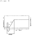
- Fig. 2 is a graphical representation useful in understanding the ignition test
- Fig. 3 is a vertical section of another embodiment of the invention
- Fig. 4 is a view showing a flexural mode of a rupture plate
- Fig. 5 is a graphical representation of the gas pressure as effected in a test tank and a gas generator in accordance with the invention.
- Any gas generator can be employed in the present invention provided that containing gas generants, at least one opening and at least one rupture plate each which is arranged on a side of upper stream with respect to each opening in a direction of a flow of the produced gas.
- a gas generator 1 shown in Fig. 1 comprises a center room, a combustion room 6 around the center room and a surrounding room around the combustion room 6 annularly.
- a squib 3 and an enhancer 4 are placed in the center room.
- the combustion room 6 accommodates gas generants 7 and coolants 8 and the surrounding room accommodates filters 10.
- the enhancer 4 is set on fire and converted into a high-temperature gas which is admitted into the combustion room 6 through orifices 5.
- the gas generants 7 are ignited in the combustion room 6 and produce a gas.
- the gas is cooled by the coolants 8, allowed to pass through inner openings 9 and the filters 10 for the removal of slag and discharged through outer openings 12 of the surrounding room.
- Each rupture plate 11 abuts against the interior wall surface of the gas generator 1 at the inner end of each outer opening 12.
- each rupture plate is arranged on a side of upper stream with respect to each opening in a direction of a flow of the produced gas.
- the arrangement can avoid an influence of an intense heat generated by the combustion of the gas generants 7 working on the rupture plates 11.
- the coolants 8 may be disposed in the surrounding room with the filter 10 and a cup accommodating the gas generants 7 may be put in the combustion room 6 so as to mask the inner openings 9, so that the cup may serve as one kind rupture plates addition to the aforementioned rupture plates 11.
- the values of the parameter B relative to the rupture plates located on a side of the inner openings 9 should be less than ones of the parameter B relative to the rupture plates 11 located on a side of the outer openings 12.
- the rupture plates 11 located on the side of the outer openings 12 are ruptured later than the rupture plates located on the side of the inner openings 9. Consequently, the gas pressure within the combustion room 6 can be more reliably maintained at a predetermined level.
- the gas generator 1 may be provided with the rupture plates on the only side of the inner openings 9.
- Provision of the gas generator 1 with the coolants 8 or the filters 10 may use or not depending on the kind of the gas generants 7.
- a variation with respect to arranging each space in the casing 2 of the gas generator 1 depends on the maximum gas pressure. For example, when the maximum gas pressure is lower than 100 [bars] as mentioned above, the strength of the casing 2 against pressure need not to be so high as to make the casing 2. Accordingly, the space in the casing 2 of the gas generator 1 need not to be divided.
- the gas generator as shown in Fig. 1 contained 25.1 g tablets of gas generants, 360 number of outer openings (i.e. diffusers) and graphite sheets as rupture plates.
- the tablet of gas generants was made of 9.4 g of 5-aminotetrazole (5-ATZ) and 15.7 g of potassium nitrate (KNO 3 ) with a press forming step and had 7 [mm] diameter and 5 [mm] height. The each outer opening had 1.5 [mm] diameter.
- the gas generator was subjected to a 60-liter tank test at a room temperature of 25 °C and characteristic curves as shown in Fig. 2 were obtained, in which t 1 referred to time required for causing the ignition to occur, Pmax referred to maximum pressure attained in the test tank, and t-Pmax referred to time required for attaining the maximum pressure Pmax.
- the time t 1 was 6.5 milliseconds
- the time t-Pmax was 60.4 milliseconds
- the maximum pressure Pmax was 235.2 [kPa].
- the gas generator as shown in Fig. 1 contained 25.1 g tablets of gas generants, 90 number of outer openings (i.e. diffusers) and graphite sheets as rupture plates.
- the tablet of gas generants was made in a manner similar to the tablet used in Example 1.
- the each outer opening had 3.0 [mm] diameter.
- the graphite sheet had a thickness of 0.76 [mm] and a tensile strength A of 55 [kgf/cm 2 ].
- the gas generator was subjected to a 60-liter tank test at a room temperature of 25 °C .
- the time t 1 was 4.6 milliseconds
- the time t-Pmax was 76.4 milliseconds
- the maximum pressure Pmax was 260.7 [kPa].
- the gas generator as shown in Fig. 1 contained 25.1 g tablets of gas generants, 20 number of outer openings (i.e. diffusers) and aluminum foils as rupture plates.
- the tablet of gas generants was made in a manner similar to the tablet used in Example 1.
- the each outer opening had 5.0 [mm] diameter.
- the aluminum foil had a thickness of 50 [ ⁇ m] and a tensile strength A of 900 [kgf/cm 2 ].
- the gas generator was subjected to a 60-liter tank test at a room temperature of 25 °C .
- the time t 1 was 3.6 milliseconds
- the time t-Pmax was 51.2 milliseconds
- the maximum pressure Pmax was 317.5 [kPa].
- the gas generator as shown in Fig. 1 contained 25.1 g tablets of gas generants, 8 number of outer openings (i.e. diffusers) and aluminum foils as rupture plates.
- the tablet of gas generants was made in a manner similar to the tablet used in Example 1.
- the two outer openings had 9.0 [mm] diameters.
- the three outer openings had 6.0 [mm] diameters and the three outer openings had 4.5 [mm] diameters respectively.
- the aluminum foil had a thickness of 100 [ ⁇ m] and a tensile strength A of 900 [kgf/cm 2 ].
- the gas generator was subjected to a 60-liter tank test at a room temperature of 25 °C .
- the time t 1 was 4.3 milliseconds
- the time t-Pmax was 49.8 milliseconds
- the maximum pressure Pmax was 289.5 [kPa].
- the gas generator as shown in Fig. 1 contained 25.1 g tablets of gas generants, 12 number of outer openings (i.e. diffusers) and stainless steel foil as rupture plates.
- the tablet of gas generants was made in a manner similar to the tablet used in Example 1.
- the each outer opening had 7.0 [mm] diameter.
- the stainless steel foil had a thickness of 46 [ ⁇ m] and a tensile strength A of 5500 [kgf/cm 2 ].
- the gas generator was subjected to a 60-liter tank test at a room temperature of 25 °C .
- the time t 1 was 5.5 milliseconds
- the time t-Pmax was 48.3 milliseconds
- the maximum pressure Pmax was 280.3 [kPa].
- a gas generator contained 25.1 g tablets of gas generants, 90 number of outer openings (i.e. diffusers) and graphite sheets as rupture plates.
- the tablet of gas generants was made of 9.4 g of 5-aminotetrazole (5-ATZ) and 15.7 g of potassium nitrate (KNO 3 ) with a press forming step and had 7 [mm] diameter and 5 [mm] height, which was made in a manner similar to the tablet used in Example 1.
- the each outer opening had 3.0 [mm] diameter.
- the graphite sheet had a thickness of 0.38 [mm] and a tensile strength A of 55 [kgf/cm 2 ].
- the gas generator was subjected to a 60-liter tank test at a room temperature of 25 °C
- a gas generator contained 25.1 g tablets of gas generants, 150 number of outer openings (i.e. diffusers) and graphite sheets as rupture plates.
- the tablet of gas generants was made in a manner similar to the tablet used in Example 1.
- the each outer opening had 2.4 [mm] diameter.
- the graphite sheet had a thickness of 1.76 [mm] and a tensile strength A of 55 [kgf/cm 2 ].
- the gas generator was subjected to a 60-liter tank test at a room temperature of 25 °C .
- a gas generator contained 25.1 g tablets of gas generants, 40 number of outer openings (i.e. diffusers) and aluminum foils as rupture plates.
- the tablet of gas generants was made in a manner similar to the tablet used in Example 1.
- the each outer opening had 3.0 [mm] diameter.
- the aluminum foil had a thickness of 136 [ ⁇ m] and a tensile strength A of 980 [kgf/cm 2 ].
- the gas generator was subjected to a 60-liter tank test at a room temperature of 25 °C .
- a gas generator contained 25.1 g tablets of gas generants, 30 number of outer openings (i.e. diffusers) and stainless steel foils as rupture plates.
- the tablet of gas generants was made in a manner similar to the tablet used in Example 1.
- the each outer opening had 6.0 [mm] diameter.
- the stainless steel foil had a thickness of 46 [ ⁇ m] and a tensile strength A of 5500 [kgf/cm 2 ].
- the gas generator was subjected to a 60-liter tank test at a room temperature of 25 °C .
- the cylindrical casing 102 of this gas generator consists of a first member 103 and a second member 104 secured to the first member 103 by means of bolts 106 so as to define a single compartment therein.
- the second member 104 has a holder portion 116 at the center for accommodating a squib 108 therein.
- the squib 108 is held in the holder portion 116 by a caulking portion 107.
- a larger diameter aluminum pipe 110 provided with openings 109 is arranged so as to surround the holder portion 116 with holding ignition agents 111 in it.
- the aluminum pipe 110 and the ignition agents are borne upon the base member 112a of a wire-net 112.
- the wire-net 112 is defined in the gas generator by the base member 112a and a cylindrical side member 112b. Tablets 113 of gas generants are filled into a space on the inner side of the cylindrical side member 112b. An open top of the first member 103 is covered by the second member 104.
- the cylindrical side wall 103a of the first member 103 has at least 40 openings 114 through which a gas is to be ejected.
- a graphite sheet 115 as rupture plates for the openings 114 is adhered to the interior surface of the cylindrical side wall 103a.
- the openings 114 are circular in the embodiment shown in Fig. 3. However, they may be elliptical or square.
- An explosive contained in the squib 108 is set on fire when a current flows through lead pins 108a and then a bridge wire (not shown) incorporated in the squib 108.
- An end of the squib 108 is ruptured and a high-temperature and high-pressure gas is ejected.
- the high-temperature and high-pressure gas ignites the ignition agents 111 in an ignition cup and converts them into a high-temperature gas.
- the high-temperature gas burns the tablets 113 of the gas generants.
- the high internal pressure of the cylindrical casing 102 is built up by a gas produced by the combustion of the tablets 113.
- the graphite sheet 115 is withstood by its heat resistant of itself and keep the internal pressure of the cylindrical casing 102 high until a prescribed pressure. Thus problem in which the combustion rate of the gas generants is slow since the required pressure can not attain is avoided even when the tablets 113 are made of the non-sodium azide gas generants.
- the internal pressure of the cylindrical casing 102 is built up to until the prescribed pressure, some portions of the graphite sheet 115 masking the openings 114 begin to rupture at some openings 114. The gas is ejected through the openings 114.
- the number of openings 114 opened by the rupture of the graphite sheet 115 depends on a value of the attained gas pressure. Accordingly, when the high gas pressure is attained, a larger number of openings 114 are opened for maintaining the gas pressure at the predetermined level.
- the rupture plates are provided on the interior surface of the cylindrical casing 102 at the inner ends of the openings 114.
- each rupture plate it is preferable for each rupture plate to be arranged on a side of upper stream with respect to each opening in a direction of a flow of the produced gas.
- rupture plates may be provided on the openings of the cylindrical partition. And also, the rupture plates may be provided on openings both of the cylindrical casing 102 and the cylindrical partition.
- the diameters of all the openings need not be equal to each other.
- a plurality of openings may have different diameters.
- a plurality of openings may have three kind of diameters and may be provided with rupture plates made of graphite sheets respectively. In this case, it possible to obtain an improved reliability in controlling the gas pressure within the gas generator.
- the rupture plates may consist of a plurality of layer.
- the rupture plates may consist of an inner layer made of a graphite sheet and an outer layer made of aluminum foil.
- a mixture of azodicarbonamide (ADCA)/KNO 3 / KClO 3 /Si rubber (as a binder) was granulated and allowed to have a grain size of 1.5 [mm] for use as gas generants, which featured a high rate of gasification and a small amount of residue. Therefore, it was not necessary for the gas generator to provide with filters for removing the residue.
- the experiment was conducted at an ordinary temperature.
- the opening ratio was the ratio of the number of open openings to the total number of openings.
- the open openings means the openings at which the rupture plates were ruptured.
- Increasing an amount of the gas generants means increasing an amount of a produced gas, in other words, becoming a gas pressure higher.
- the number of open openings increased as the amount of the gas generants increased.
- the opening area increased as the gas pressure increased.
- the opening area means the total area of the open openings.
- Fig.5 shows a characteristics of a 60 liter-tank test of the present invention.
- the solid curve represents how the gas pressure [bars] in the gas generator varies with time
- the dot-dash curve represents how the pressure [Pa] in the tank used in the 60-liter tank test vary with time.
- the gas pressure in the gas generator reaches a maximum value at a point a and maintains at about 50 [bars] during a lapse of a prescribed time and then follows a gradual pressure reduction.
- the casing of the gas generator need not be highly pressure-resistant. Consequently, a reduction in weight is achieved and the space requirement is reduced.
- the gas generator in accordance with the present invention permits the gas generants having a high rate of gasification to be employed even if the gas generants have a high pressure exponent. And then a reduction in weight is achieved and the space requirement is further reduced by using the gas generants having high rate of gasification.
- gas generants are the gas generants such non-azide gas generants which have a burning rate greatly affected by a change in the ambient temperature
- the gas generator according to the present invention can burn the gas generants in a stabilized condition and at a riskless burning rate.
- a gas generator wherein even gas generants which do not contain azide and therefore has a burning rate greatly affected by a change in the ambient temperature can be burned in a stabilized condition and at a riskless burning rate.
- the gas generator has openings through which a gas produced from gas generants accommodated in the gas generator is allowed to pass.
- the gas generator further has rupture plates which abut against the interior wall surface of the gas generator so as to mask the openings .
- the rupture plates are made of nonmetal materials in whole or in part.
- the nonmetal materials have melting points which are higher than or equal to 500 °C.
Landscapes
- Engineering & Computer Science (AREA)
- Mechanical Engineering (AREA)
- Physics & Mathematics (AREA)
- Fluid Mechanics (AREA)
- Chemical & Material Sciences (AREA)
- Chemical Kinetics & Catalysis (AREA)
- Combustion & Propulsion (AREA)
- Organic Chemistry (AREA)
- Air Bags (AREA)
- Feeding, Discharge, Calcimining, Fusing, And Gas-Generation Devices (AREA)
Claims (5)
- Gasgenerator, welcher umfaßt:dadurch gekennzeichnet, daß die Berstscheiben (11; 115) ganz oder teilweise aus nichtmetallischen Materialien hergestellt sind, und die nichtmetallischen Materialien Schmelzpunkte aufweisen, welche höher als oder gleich 500 °C sind;Öffnungen (12; 114), durch welche ein Gas fließen kann, das von in dem Gasgenerator untergebrachten Gaserzeugern (7; 113) erzeugt wird, undBerstscheiben (11; 115), welche so gegen die inneren Wandflächen des Gasgenerators (1; 101) stoßen, daß sie die Öffnungen (12; 114) abdecken, und jede von diesen in Bezug auf jede Öffnung (12; 114) in einer Richtung eines Flusses des erzeugten Gases stromaufwärts angeordnet ist,
wobei jede Dicke t [cm] der Berstscheiben (11; 115) und der Kreisäquivalentdurchmesser D [cm] der Öffnungen (12; 114) durch die folgende Gleichung (1) gegeben ist: - Der Gasgenerator nach Anspruch 1, wobei der Gasgenerator (1; 101) eine Vielzahl von Öffnungen (12; 114) und eine Vielzahl von Berstscheiben (11; 115) aufweist, und
die Vielzahl der Berstscheiben (11; 115) nacheinander gemäß eines inneren Druckes in den Gasgenerator (1; 101) bersten. - Der Gasgenerator nach Anspruch 1 oder 2, wobei die nichtmetallischen Materialien flexibel sind.
- Der Gasgenerator nach einem der Ansprüche 1 bis 3, wobei die nichtmetallischen Materialien Graphitblätter oder hauptsächlich aus Graphit bestehende Blätter sind.
- Der Gasgenerator nach einem der Ansprüche 1 bis 4, wobei der maximale innere Druck in dem Gasgenerator (1; 101) niedriger als 100 [bar] ist.
Applications Claiming Priority (7)
| Application Number | Priority Date | Filing Date | Title |
|---|---|---|---|
| JP26172594 | 1994-09-30 | ||
| JP26172594 | 1994-09-30 | ||
| JP9979995 | 1995-03-31 | ||
| JP9979995 | 1995-03-31 | ||
| JP18345395 | 1995-06-26 | ||
| JP18345395 | 1995-06-26 | ||
| EP95932221A EP0783997B1 (de) | 1994-09-30 | 1995-09-25 | Gasgenerator |
Related Parent Applications (1)
| Application Number | Title | Priority Date | Filing Date |
|---|---|---|---|
| EP95932221A Division EP0783997B1 (de) | 1994-09-30 | 1995-09-25 | Gasgenerator |
Publications (2)
| Publication Number | Publication Date |
|---|---|
| EP1359065A1 EP1359065A1 (de) | 2003-11-05 |
| EP1359065B1 true EP1359065B1 (de) | 2005-08-31 |
Family
ID=27309050
Family Applications (2)
| Application Number | Title | Priority Date | Filing Date |
|---|---|---|---|
| EP95932221A Revoked EP0783997B1 (de) | 1994-09-30 | 1995-09-25 | Gasgenerator |
| EP03016047A Expired - Lifetime EP1359065B1 (de) | 1994-09-30 | 1995-09-25 | Gasgenerator |
Family Applications Before (1)
| Application Number | Title | Priority Date | Filing Date |
|---|---|---|---|
| EP95932221A Revoked EP0783997B1 (de) | 1994-09-30 | 1995-09-25 | Gasgenerator |
Country Status (5)
| Country | Link |
|---|---|
| EP (2) | EP0783997B1 (de) |
| JP (1) | JP2862023B2 (de) |
| KR (1) | KR970706145A (de) |
| DE (2) | DE69533403T2 (de) |
| WO (1) | WO1996010494A1 (de) |
Families Citing this family (17)
| Publication number | Priority date | Publication date | Assignee | Title |
|---|---|---|---|---|
| US6234521B1 (en) | 1996-04-08 | 2001-05-22 | Daicel Chemical Industries, Ltd. | Airbag inflator and an airbag apparatus |
| JP2989788B2 (ja) | 1996-10-31 | 1999-12-13 | ダイセル化学工業株式会社 | エアバッグ用ガス発生器及びエアバッグ装置 |
| US5765866A (en) * | 1997-02-19 | 1998-06-16 | Breed Automotive Technology, Inc. | Airbag inflator employing gas generating compositions containing mica |
| EP0867347B1 (de) * | 1997-03-24 | 2004-07-07 | Daicel Chemical Industries, Ltd. | Gaserzeugende Tabletten und Gasgenerator |
| US6562161B1 (en) | 1997-03-24 | 2003-05-13 | Daicel Chemical Industries, Ltd. | Gas generating compositions for air bag |
| JP2926040B2 (ja) | 1997-05-09 | 1999-07-28 | ダイセル化学工業株式会社 | エアバッグ用ガス発生器及びエアバッグ装置 |
| US6406060B1 (en) | 1997-05-09 | 2002-06-18 | Daicel Chemical Industries, Ltd. | Gas generator for airbag and airbag system |
| US6135496A (en) * | 1997-05-09 | 2000-10-24 | Daicel Chemical Industries, Ltd. | Gas generator for air bag and air bag system |
| JPH11105661A (ja) | 1997-10-08 | 1999-04-20 | Daicel Chem Ind Ltd | エアバッグ用ガス発生器及びエアバッグ装置 |
| JP2963086B1 (ja) | 1997-12-26 | 1999-10-12 | ダイセル化学工業株式会社 | エアバッグ用ガス発生器及びエアバッグ装置 |
| FR2796936B1 (fr) | 1999-07-30 | 2001-09-14 | Livbag Snc | Generateur pyrotechnique de gaz a double securite d'ouverture |
| TW469235B (en) * | 1999-10-04 | 2001-12-21 | Daicel Chem | Gas generator for air bag and air bag device |
| JP4757375B2 (ja) * | 2000-09-22 | 2011-08-24 | ダイセル化学工業株式会社 | エアバッグ用ガス発生器 |
| JP2001219810A (ja) * | 2000-12-11 | 2001-08-14 | Daicel Chem Ind Ltd | エアバッグ用ガス発生器及びエアバッグ装置 |
| SE520973C2 (sv) * | 2001-01-19 | 2003-09-16 | Bofors Bepab Ab | Krutmotor, krut- hybridgasgenerator samt sätt att styra brinntrycket i en krutmotor |
| EP1386793A4 (de) * | 2001-04-10 | 2005-04-06 | Nippon Kayaku Kk | Gasgenerator |
| EP3135543B2 (de) | 2014-04-25 | 2022-09-28 | Nippon Kayaku Kabushiki Kaisha | Gasgenerator |
Family Cites Families (8)
| Publication number | Priority date | Publication date | Assignee | Title |
|---|---|---|---|---|
| FR2116948A5 (de) * | 1970-12-11 | 1972-07-21 | France Etat | |
| DE2824701C2 (de) * | 1978-06-06 | 1982-11-11 | Bayern-Chemie Gesellschaft für flugchemische Antriebe mbH, 8261 Aschau | Gasgenerator |
| US4817828A (en) | 1986-10-03 | 1989-04-04 | Trw Automotive Products Inc. | Inflatable restraint system |
| DE3831641A1 (de) | 1988-08-09 | 1990-02-15 | Daimler Benz Ag | Gasgenerator zum fuellen einer gaskissen-rueckhalteeinrichtung |
| JP2535420B2 (ja) * | 1989-10-19 | 1996-09-18 | 日本工機株式会社 | シ―トベルト巻取用動力発生装置のガス発生器 |
| US5269561A (en) | 1992-07-06 | 1993-12-14 | Morton International, Inc. | Vented gas passenger side air bag inflator |
| JPH0632690A (ja) * | 1992-07-13 | 1994-02-08 | Nippon Koki Kk | エアバッグ用ガス発生剤 |
| JPH06344855A (ja) * | 1993-06-08 | 1994-12-20 | Takata Kk | エアバッグ装置のインフレータ |
-
1995
- 1995-09-25 DE DE69533403T patent/DE69533403T2/de not_active Expired - Fee Related
- 1995-09-25 EP EP95932221A patent/EP0783997B1/de not_active Revoked
- 1995-09-25 JP JP8511596A patent/JP2862023B2/ja not_active Expired - Fee Related
- 1995-09-25 DE DE69534424T patent/DE69534424T2/de not_active Expired - Fee Related
- 1995-09-25 WO PCT/JP1995/001926 patent/WO1996010494A1/ja not_active Ceased
- 1995-09-25 EP EP03016047A patent/EP1359065B1/de not_active Expired - Lifetime
-
1997
- 1997-03-22 KR KR1019970701882A patent/KR970706145A/ko not_active Ceased
Also Published As
| Publication number | Publication date |
|---|---|
| DE69533403D1 (de) | 2004-09-23 |
| WO1996010494A1 (en) | 1996-04-11 |
| JP2862023B2 (ja) | 1999-02-24 |
| EP0783997A4 (de) | 2001-01-17 |
| EP1359065A1 (de) | 2003-11-05 |
| EP0783997A1 (de) | 1997-07-16 |
| DE69534424T2 (de) | 2006-07-06 |
| DE69533403T2 (de) | 2005-08-25 |
| EP0783997B1 (de) | 2004-08-18 |
| DE69534424D1 (de) | 2005-10-06 |
| KR970706145A (ko) | 1997-11-03 |
Similar Documents
| Publication | Publication Date | Title |
|---|---|---|
| EP1359065B1 (de) | Gasgenerator | |
| KR100551961B1 (ko) | 가스발생기로부터 이와 관련된 에어백으로의 가스의 흐름을 제어하는 방법 및 에어백용 인플레이터 | |
| US5431103A (en) | Gas generant compositions | |
| CN100445137C (zh) | 气体发生器 | |
| US7398996B2 (en) | Gas producer | |
| US6918976B2 (en) | Gas generating composition | |
| WO2005014344A1 (ja) | ガス発生器 | |
| JPWO1996010494A1 (ja) | ガス発生器 | |
| US6808204B1 (en) | Hybrid inflator | |
| EP1449724B1 (de) | Aufblasvorrichtung | |
| KR100500808B1 (ko) | 기체 발생기의 자동 점화 | |
| US20070063495A1 (en) | Installation structure of gas producer and air bag module | |
| KR100780894B1 (ko) | 자동발화기능을 갖는 가스발생기 | |
| JP5391440B2 (ja) | パイロ型ガス発生器及びガス発生剤組成物の成型体 | |
| JP3267546B2 (ja) | エアバッグ用ガス発生器及びエアバッグ装置 | |
| JPH0995202A (ja) | エアバッグ用ガス発生器 | |
| CN100540513C (zh) | 充气器和气囊系统 | |
| KR100523976B1 (ko) | 에어백용 인플레이터 및 에어백 장치 | |
| JP2001206189A (ja) | エアバッグ用ガス発生器及びエアバッグ装置 | |
| KR20000016226A (ko) | 질산암모늄, 질산구아니딘 및 과염소산칼륨의 공융 혼합물 |
Legal Events
| Date | Code | Title | Description |
|---|---|---|---|
| PUAI | Public reference made under article 153(3) epc to a published international application that has entered the european phase |
Free format text: ORIGINAL CODE: 0009012 |
|
| AC | Divisional application: reference to earlier application |
Ref document number: 0783997 Country of ref document: EP Kind code of ref document: P |
|
| AK | Designated contracting states |
Kind code of ref document: A1 Designated state(s): DE FR GB IT SE |
|
| 17P | Request for examination filed |
Effective date: 20040402 |
|
| AKX | Designation fees paid |
Designated state(s): DE FR GB IT SE |
|
| 17Q | First examination report despatched |
Effective date: 20040819 |
|
| GRAP | Despatch of communication of intention to grant a patent |
Free format text: ORIGINAL CODE: EPIDOSNIGR1 |
|
| GRAS | Grant fee paid |
Free format text: ORIGINAL CODE: EPIDOSNIGR3 |
|
| GRAA | (expected) grant |
Free format text: ORIGINAL CODE: 0009210 |
|
| AC | Divisional application: reference to earlier application |
Ref document number: 0783997 Country of ref document: EP Kind code of ref document: P |
|
| AK | Designated contracting states |
Kind code of ref document: B1 Designated state(s): DE FR GB IT SE |
|
| PG25 | Lapsed in a contracting state [announced via postgrant information from national office to epo] |
Ref country code: IT Free format text: LAPSE BECAUSE OF FAILURE TO SUBMIT A TRANSLATION OF THE DESCRIPTION OR TO PAY THE FEE WITHIN THE PRESCRIBED TIME-LIMIT;WARNING: LAPSES OF ITALIAN PATENTS WITH EFFECTIVE DATE BEFORE 2007 MAY HAVE OCCURRED AT ANY TIME BEFORE 2007. THE CORRECT EFFECTIVE DATE MAY BE DIFFERENT FROM THE ONE RECORDED. Effective date: 20050831 |
|
| REG | Reference to a national code |
Ref country code: GB Ref legal event code: FG4D |
|
| REF | Corresponds to: |
Ref document number: 69534424 Country of ref document: DE Date of ref document: 20051006 Kind code of ref document: P |
|
| PG25 | Lapsed in a contracting state [announced via postgrant information from national office to epo] |
Ref country code: SE Free format text: LAPSE BECAUSE OF FAILURE TO SUBMIT A TRANSLATION OF THE DESCRIPTION OR TO PAY THE FEE WITHIN THE PRESCRIBED TIME-LIMIT Effective date: 20051130 |
|
| ET | Fr: translation filed | ||
| PLBE | No opposition filed within time limit |
Free format text: ORIGINAL CODE: 0009261 |
|
| STAA | Information on the status of an ep patent application or granted ep patent |
Free format text: STATUS: NO OPPOSITION FILED WITHIN TIME LIMIT |
|
| 26N | No opposition filed |
Effective date: 20060601 |
|
| PGFP | Annual fee paid to national office [announced via postgrant information from national office to epo] |
Ref country code: FR Payment date: 20060922 Year of fee payment: 12 Ref country code: GB Payment date: 20060922 Year of fee payment: 12 |
|
| PGFP | Annual fee paid to national office [announced via postgrant information from national office to epo] |
Ref country code: DE Payment date: 20061031 Year of fee payment: 12 |
|
| GBPC | Gb: european patent ceased through non-payment of renewal fee |
Effective date: 20070925 |
|
| PG25 | Lapsed in a contracting state [announced via postgrant information from national office to epo] |
Ref country code: DE Free format text: LAPSE BECAUSE OF NON-PAYMENT OF DUE FEES Effective date: 20080401 |
|
| REG | Reference to a national code |
Ref country code: FR Ref legal event code: ST Effective date: 20080531 |
|
| PG25 | Lapsed in a contracting state [announced via postgrant information from national office to epo] |
Ref country code: FR Free format text: LAPSE BECAUSE OF NON-PAYMENT OF DUE FEES Effective date: 20071001 |
|
| PG25 | Lapsed in a contracting state [announced via postgrant information from national office to epo] |
Ref country code: GB Free format text: LAPSE BECAUSE OF NON-PAYMENT OF DUE FEES Effective date: 20070925 |