EP1359083A2 - Fahrzeuglenkung - Google Patents
Fahrzeuglenkung Download PDFInfo
- Publication number
- EP1359083A2 EP1359083A2 EP03009264A EP03009264A EP1359083A2 EP 1359083 A2 EP1359083 A2 EP 1359083A2 EP 03009264 A EP03009264 A EP 03009264A EP 03009264 A EP03009264 A EP 03009264A EP 1359083 A2 EP1359083 A2 EP 1359083A2
- Authority
- EP
- European Patent Office
- Prior art keywords
- rotating member
- side rotating
- steering
- operating
- actuator
- Prior art date
- Legal status (The legal status is an assumption and is not a legal conclusion. Google has not performed a legal analysis and makes no representation as to the accuracy of the status listed.)
- Withdrawn
Links
Images


Classifications
-
- B—PERFORMING OPERATIONS; TRANSPORTING
- B62—LAND VEHICLES FOR TRAVELLING OTHERWISE THAN ON RAILS
- B62D—MOTOR VEHICLES; TRAILERS
- B62D5/00—Power-assisted or power-driven steering
- B62D5/04—Power-assisted or power-driven steering electrical, e.g. using an electric servo-motor connected to, or forming part of, the steering gear
- B62D5/0457—Power-assisted or power-driven steering electrical, e.g. using an electric servo-motor connected to, or forming part of, the steering gear characterised by control features of the drive means as such
- B62D5/0481—Power-assisted or power-driven steering electrical, e.g. using an electric servo-motor connected to, or forming part of, the steering gear characterised by control features of the drive means as such monitoring the steering system, e.g. failures
- B62D5/0484—Power-assisted or power-driven steering electrical, e.g. using an electric servo-motor connected to, or forming part of, the steering gear characterised by control features of the drive means as such monitoring the steering system, e.g. failures for reaction to failures, e.g. limp home
-
- B—PERFORMING OPERATIONS; TRANSPORTING
- B62—LAND VEHICLES FOR TRAVELLING OTHERWISE THAN ON RAILS
- B62D—MOTOR VEHICLES; TRAILERS
- B62D5/00—Power-assisted or power-driven steering
- B62D5/008—Changing the transfer ratio between the steering wheel and the steering gear by variable supply of energy, e.g. by using a superposition gear
Definitions
- the present invention relates to a vehicle steering apparatus in which the steering characteristics of the vehicle can be altered by the control of an actuator.
- Such steering apparatuses include an apparatus with a so-called steer-by-wire system in which an operating member is not mechanically connected to the wheels of the vehicle, and an apparatus in which an operating member is mechanically connected to the wheels of the vehicle.
- the steering characteristics are altered by transmitting the movement of the steering actuator to the wheels of the vehicle so that a variation in the steering angle is generated.
- the rotation of an input shaft corresponding to the operation of the steering wheel is transmitted to an output shaft via a variable transmission ratio mechanism such as a planetary gear mechanism or the like, the rotation of this output shaft is transmitted to the wheels of the vehicle so that a variation in the steering angle is generated, and the steering characteristics are altered by driving the ring gears or the like in the planetary gear mechanism by the steering actuator.
- a fail-safe function which is used to steer the wheels of the vehicle in the case of trouble with the actuator or control system is required.
- a system has been proposed in which a fail-safe function is realized by using a clutch or the like to connect an operating side rotating member that is mechanically connected to the operating member with a vehicle wheel side rotating member that is mechanically connected to the wheels of the vehicle in the case of such trouble in the actuator or control system.
- a fail-safe function is realized by using a clutch or the like to connect an operating side rotating member that is mechanically connected to the operating member with a vehicle wheel side rotating member that is mechanically connected to the wheels of the vehicle in the case of such trouble in the actuator or control system.
- the operating member is mechanically connected to the wheels of the vehicle via a variable transmission ratio mechanism
- the movement of the wheels of the vehicle and the movement of the operating member interfere with each other when control for the purpose of compensating for fluctuations in the steering angle caused by irregularities in the road surface or the like is performed. Accordingly, a smooth operating feeling that is unaffected by irregularities in the road surface or the like, and operation of the operating member without any resistance, are impossible.
- the vehicle steering apparatus of the present invention comprises an operating member, a steering actuator, a steering gear which transmits the movement of the steering actuator to the vehicle wheels so that a variation in the steering angle is generated, a control system which is capable of controlling the steering actuator so that the steering angle varies in accordance with the operation of the operating member, an operating side rotating member which is mechanically connected to the operating member so as to rotate in accordance with the operation of this operating member, a vehicle wheel side rotating member which is mechanically connected to the vehicle wheels so as to rotate in accordance with the variation in the steering angle, and a transmission mechanism which mechanically connects the operating side rotating member and the vehicle wheel side rotating member to each other so that the transmission of rotation is possible, and so that the ratio of the rotational transmission can be varied.
- the operating side rotating member that is mechanically connected to the operating member and the vehicle wheel side rotating member that is mechanically connected to the vehicle wheels are capable of the mutual transmission of rotation via the transmission mechanism, the reliability of the fail-safe function can be improved.
- the vehicle steering apparatus of the present invention comprise an adjustment actuator that is used to adjust the ratio of rotational transmission by the transmission mechanism, and a control system which is capable of controlling this adjustment actuator so that the ratio of rotational transmission by the transmission mechanism can be varied.
- the vehicle steering apparatus of the present invention can comprise means for determining the amount of operation of the operating member, means for storing in memory a set relationship between the amount of operation of the operating member and the target steering angle, means for calculating the target steering angle from the determined amount of operation of the operating member and the stored relationship, means for determining the actual steering angle, means for storing in memory a set relationship between the amount of operation of the operating member and the target operating torque, means for calculating the target operating torque from the determined amount of operation of the operating member and the stored relationship, and means for determining the actual operating torque of the operating member.
- the abovementioned steering actuator is made controllable so that the deviation between the target steering angle and actual steering angle is reduced
- the abovementioned adjustment actuator is made controllable so that the deviation between the target operating torque and the actual operating torque is reduced.
- the adjustment actuator can be made controllable so that a torque oriented in an arbitrary direction acts on the operating member.
- the operating torque that acts on the operating member when the steering angle is varied can be reduced to zero by making the abovementioned adjustment actuator controllable so that the rotational force acting on the operating side rotating member is reduced to zero.
- the torque that is caused to act on the operating member by the adjustment actuator can be controlled.
- the vehicle steering apparatus of the present invention comprise abnormality detection means for detecting an abnormality in the adjustment actuator, and a restraining mechanism that is capable of restraining the variation in the ratio of the rotational transmission between the operating side rotating member and the vehicle wheel side rotating member, and that the variation in the ratio of the rotational transmission between the operating side rotating member and the vehicle wheel side rotating member is restrained by the restraining mechanism, the driving of the adjustment actuator is stopped, and the steering actuator is controlled so that a steering assist torque is caused to act, in cases where the abnormality is detected in the adjustment actuator.
- the steering apparatus can function as a power steering apparatus in cases where an abnormality is detected in the adjustment actuator.
- the vehicle steering apparatus of the present invention comprise abnormality detection means for detecting an abnormality in the adjustment actuator, and a restraining mechanism that is capable of restraining the variation in the ratio of the rotational transmission between the operating side rotating member and the vehicle wheel side rotating member, and that the variation in the ratio of the rotational transmission between the operating side rotating member and the vehicle wheel side rotating member is restrained by the restraining mechanism, and the driving of the adjustment actuator and steering actuator is stopped, in cases where the abnormality is detected in the adjustment actuator.
- the steering apparatus can function as a manual type steering apparatus in cases where an abnormality is detected in the adjustment actuator.
- the vehicle steering apparatus of the present invention comprise abnormality detection means for detecting an abnormality in the adjustment actuator, and that the driving of the adjustment actuator is stopped, and the transmission of rotation between the operating side rotating member and the vehicle wheel side rotating member is stopped, in cases where the abnormality is detected in the adjustment actuator.
- the steering angle can be varied by controlling the steering actuator in accordance with the operation of the operating member, and there is no interference with the operation of the operating member.
- the vehicle steering apparatus of the present invention comprise abnormality detection means for detecting an abnormality in the adjustment actuator, a restraining mechanism that is capable of restraining the variation in the ratio of the rotational transmission between the operating side rotating member and the vehicle wheel side rotating member, and a change-over switch for the abnormality handling modes that is used in cases where the abnormality is detected in the adjustment actuator, and that the switching of the abovementioned switch enables selection of one of three modes, i.
- a mode in which the steering apparatus is caused to function as a power steering apparatus a mode in which the steering apparatus is caused to function as a manual type steering apparatus, or a mode in which the steering actuator is controlled in accordance with the operation of the operating member, can be selected.
- the vehicle steering apparatus of the present invention comprise abnormality detection means for detecting an abnormality in the steering actuator, and a restraining mechanism that is capable of restraining the variation in the ratio of the rotational transmission between the operating side rotating member and the vehicle wheel side rotating member, and that the variation in the ratio of the rotational transmission between the operating side rotating member and the vehicle wheel side rotating member is restrained by the restraining mechanism, the driving of the steering actuator is stopped, and the adjustment actuator is controlled so that a steering assist torque is caused to act, in cases where the abnormality is detected in the steering actuator.
- the steering apparatus can be caused to function as a power steering apparatus by the adjustment actuator in cases where an abnormality is detected in the steering actuator.
- the vehicle steering apparatus of the present invention comprise abnormality detection means for detecting an abnormality in the steering actuator, and a restraining mechanism that is capable of restraining the variation in the ratio of the rotational transmission between the operating side rotating member and the vehicle wheel side rotating member, and that the variation in the ratio of the rotational transmission between the operating side rotating member and the vehicle wheel side rotating member is restrained by the restraining mechanism, and the driving of the adjustment actuator and the steering actuator is stopped, in cases where the abnormality is detected in the steering actuator.
- the steering apparatus can function as a manual type steering apparatus in cases where an abnormality is detected in the steering actuator.
- the vehicle steering apparatus of the present invention comprises abnormality detection means for detecting an abnormality in the steering actuator, and means for detecting a variable that expresses the operating state of the vehicle, and that the driving of the steering actuator is stopped, and the adjustment actuator is controlled so that the ratio of the rotational transmission between the operating side rotating member and the vehicle wheel side rotating member is varied in accordance with the detected variable that expresses the operating state of the vehicle, in cases where the abnormality is detected in the steering actuator.
- the steering apparatus can function as a steering apparatus that is capable of altering the steering characteristics in accordance with the operating state of the vehicle.
- the vehicle steering apparatus of the present invention comprises abnormality detection means for detecting an abnormality in the steering actuator, a restraining mechanism that is capable of restraining the variation in the ratio of the rotational transmission between the operating side rotating member and the vehicle wheel side rotating member, means for detecting a variable that expresses the operating state of the vehicle, and a change-over switch for the abnormality handling modes that is used in cases where the abnormality is detected in the steering actuator, and that the switching of the abovementioned switch enables selection of one of three modes, i.
- either a mode in which the steering apparatus can be caused to function as a power steering apparatus, a mode in which the steering apparatus can be caused to function as a manual type steering apparatus, or a mode in which the steering characteristics can be altered in accordance with the operating state of the vehicle, can be selected in cases where an abnormality is detected in the steering actuator.
- the vehicle steering apparatus of the present invention comprises abnormality detection means for detecting an abnormality in the adjustment actuator, abnormality detection means for detecting an abnormality in the steering actuator, and a restraining mechanism that is capable of restraining the variation in the ratio of the rotational transmission between the operating side rotating member and the vehicle wheel side rotating member, and that the variation in the ratio of the rotational transmission between the operating side rotating member and the vehicle wheel side rotating member is restrained by the restraining mechanism, and the driving of the adjustment actuator and the steering actuator is stopped, in cases where the abnormality in the adjustment actuator and the abnormality in the steering actuator are detected.
- the steering apparatus can function as a manual type steering apparatus in cases where abnormalities are detected in the adjustment actuator and steering actuator.
- the vehicle steering apparatus of the present invention comprises abnormality detection means for detecting an abnormality in the control system of the steering actuator and the adjustment actuator, and a restraining mechanism that is capable of restraining the variation in the ratio of the rotational transmission between the operating side rotating member and the vehicle wheel side rotating member, and that the variation in the ratio of the rotational transmission between the operating side rotating member and the vehicle wheel side rotating member is restrained by the restraining mechanism, and the driving of the adjustment actuator and the steering actuator be stopped, in cases where the abnormality is detected in the control system.
- the steering apparatus can function as a manual type steering apparatus.
- the abovementioned transmission mechanism have three elements that are capable of relative rotation, that the ratio of the rotational transmission between two of the elements can be varied in accordance with the variation in the rotational speed of the third element, that one of the three elements is connected to the operating side rotating member, that one of the elements that is not connected to the operating side rotating member is connected to the vehicle wheel side rotating member, that the remaining element is driven by the adjustment actuator, and that the ratio of the rotational transmission is varied by controlling the adjustment actuator by means of the control system.
- the abovementioned transmission mechanism has a planetary gear mechanism in which a planetary gear that engages with a sun gear and a ring gear is held by a carrier, and this sung gear, ring gear and carrier can be taken as the abovementioned three elements that are capable of relative rotation.
- the transmission mechanism can easily be structured from a known rotational transmission mechanism.
- the transmission of rotation between the operating side rotating member and the vehicle wheel side rotating member via the transmission mechanism can be stopped in a state in which a mechanical connection between the operating side rotating member and the vehicle wheel side rotating member is maintained by the transmission mechanism.
- the operating torque can be reduced to zero when there is a variation in the steering angle without any need for the adjustment actuator or control system.
- a fail-safe function can be securely obtained by means of a simple structure, and without any need for lowering the steering feeling experienced by the driver, in a vehicle steering apparatus in which the steering angle is varies by the control of an actuator.
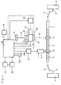
- the vehicle steering apparatus 1 shown in Fig. 1 comprises an operating member 2 in the shape of a steering wheel, a steering actuator 3, and a steering gear 5 which transmits the movement of the steering actuator 3 to the left and right vehicle wheels 4 so that a variation in the steering angle is generated.
- a known electric motor such as a brushless motor or a hydraulic motor can be adopted as the steering actuator 3.
- the steering gear 5 has a motion converting mechanism that converts the rotational motion of the output shaft of the steering actuator 3 into the linear motion of a steering rod 7.
- the movement of the steering rod 7 is transmitted to the vehicle wheels 4 via tie rods 8 and knuckle arms 9, so that the toe angle of the vehicle wheels 4 varies.
- this motion converting mechanism is structured from a pinion 10 that is attached to the output shaft of the steering actuator 3, and a rack 11 that engages with this pinion 10.
- the rack 11 is formed on the steering rod 7.
- An operating side rotating member 12 in the shape of a shaft is mechanically connected to the operating member 2 so that this operating side rotating member 12 rotates in accordance with the operation of the operating member 2.
- the operating side rotating member 12 of the present embodiment is attached so that this member rotates together with the operating member 2. It is sufficient if the operating side rotating member 12 is mechanically connected to the operating member 2 so that this operating side rotating member 12 rotates in accordance with the operation of the operating member 2; for example, the members can be connected via a speed-change gear mechanism.
- a vehicle wheel side rotating member 13 is mechanically connected to the vehicle wheels 4 so that this vehicle wheel side rotating member 13 rotates in accordance with the variation in the steering angle.
- the vehicle wheel side rotating member 13 of the present embodiment is connected so that this vehicle wheel side rotating member 13 rotates together with a pinion 14 that engages with the abovementioned rack 11. It is sufficient if the vehicle wheel side rotating member 13 is mechanically connected to the vehicle wheels 14 so that this vehicle wheel side rotating member 13 rotates in accordance with the variation in the steering angle; the connection with the vehicle wheels 14 is not limited to a connection using a rack 11 and pinion 14.
- the operating side rotating member 12 and vehicle wheel side rotating member 13 are connected to each other by a transmission mechanism 20 so that the transmission of rotation between the respective members is possible.
- the transmission mechanism 20 is capable of varying the ratio of the rotational transmission between the operating side rotating member 12 and vehicle wheel side rotating member 13.
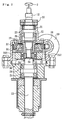
- the transmission mechanism 20 has a housing 23, and a planetary gear mechanism 30 which is covered by this housing 23.
- the housing 23 supports the operating side rotating member 12 via bearings 21 and 22, and supports the vehicle wheel side rotating member 13 via bearings 24 and 25.
- the vehicle wheel side rotating member 13 and operating side rotating member 12 are disposed coaxially with a gap interposed.
- the transmission of rotation between the operating side rotating member 12 and vehicle wheel side rotating member 13 is accomplished via the planetary gear mechanism 30.
- the planetary gear mechanism 30 has a sun gear 31, a ring gear 32 and a carrier 34 as three elements that are capable of relative rotation.
- a planetary gear 33 that engages with the sun gear 31 and ring gear 32 is held by the carrier 34.
- the sun gear 31 is mechanically connected to the end portion of the operating side rotating member 12 so that this sun gear 31 rotates together with the operating side rotating member 12.
- the carrier 34 is connected to the vehicle wheel side rotating member 13 so that the carrier 34 rotates together with the vehicle wheel side rotating member 13.
- the ring gear 32 is fastened via bolts 362 to a holder 36 that surrounds the operating side rotating member 12. This holder 36 is supported via a bearing 29 by a tubular member 35 that is fastened to the housing 23 so as to surround the operating side rotating member 12.
- a worm wheel 37 is fastened to the outer circumference of the holder 36 so that the worm wheel 37 rotates together with the holder 36.
- a worm 38 that engages with the worm wheel 37 is supported by the housing 23.
- the worm 38 is driven by a adjustment actuator 39 attached to the housing 23, so that the ring gear 32, which is an element of the planetary gear mechanism 30, is driven by the adjustment actuator 39.
- a known electric motor such as a brushless motor or hydraulic motor can be adopted as the adjustment actuator 39.
- the ratio of the rotational transmission between the operating side rotating member 12 and vehicle wheel side rotating member 13 can be varied by varying the rotational speed of the ring gear 32 by means of the adjustment actuator 39.
- a control system for the steering actuator 3 and adjustment actuator 39 is provided.
- an operation amount sensor 41 which determines the rotational angle of the operating side rotating member 12 as the amount ⁇ h of operation of the operating member 2
- a steering angle sensor 42 which determines the rotational angle of the vehicle wheel side rotating member 13 corresponding to the amount of steering of the vehicle wheels 4 as the actual steering angle ⁇
- a speed sensor 43 which detects the vehicle speed V as a variable that expresses the operating state of the vehicle
- a torque sensor 46 which detects the actual operating torque Th of the operating member 2 are connected to a control device 45 comprised of a computer.
- the steering angle can be varied in accordance with the operation of the operating member 2 by controlling the steering actuator 3 by means of the control system via a driving circuit 47.
- This gain K1 can be set as a function of the vehicle speed so that the gain K1 increases as the speed decreases; accordingly, as shown in Fig.
- the target steering angle ⁇ * is proportional to the amount of operation ⁇ h, and the proportionality constant increases as the speed decreases.
- the steering actuator 3 is controlled so that the deviation between the target steering angle ⁇ * and the detected actual steering angle ⁇ decreases.
- the ratio of the rotational transmission by the transmission mechanism 20 can be varied by controlling the adjustment actuator 39 by means of the control system via the control circuit 48. Specifically, the ratio of the rotation transmission between the operating side rotating member 12 and vehicle wheel side rotating member 13 is determined in accordance with the rotational speed of the adjustment actuator 39 that drives the ring gear 32. Accordingly, in cases where the ratio of the rotational transmission between the operating side rotating member 12 which is caused to rotate as a result of the operation of the operating member 2 by the driver and the vehicle wheel side rotating member 13 which is caused to rotate by the variation in the steering angle ⁇ is equal to the ratio of the rotational transmission that is determined in accordance with the rotational speed of the adjustment actuator 39, no torque acts other than the torque that is caused to act on the operating member 2 by the driver.
- the target operating torque Th* is proportional to the amount of operation ⁇ h, as shown in Fig. 4 (B).
- the adjustment actuator 39 is controlled so that the deviation between the target operating torque Th* and the actual operating torque Th is reduced.
- the adjustment actuator 39 is controlled so that a torque that makes the operating member 1 return to the neutral position generates.
- the actual operating torque Th can be caused to track the target operating torque Th* by varying the ratio of the rotational transmission between the operating side rotating member 12 and vehicle wheel side rotating member 13 by the control of the adjustment actuator 39, so that the movement of the vehicle wheels 4 and the movement of the operating member 1 can be prevented from interfering with each other.
- the actual operating torque Th is not necessarily limited to a torque that makes the operating member 1 return to the neutral position; the target operating torque Th* can be set so as to act in an arbitrary direction in accordance with the operating conditions.
- Abnormality detection means for detecting an abnormality in the adjustment actuator 39 is provided.
- the control device 45 monitors the deviation between the command value sent to the adjustment actuator 39 from the control device 45 and the output value of the adjustment actuator 39 determined from the value detected by the rotational angle sensor 44, and judges that the adjustment actuator 39 is acting abnormally if the deviation is equal to or greater than a set value.
- a restraining mechanism 50 that is capable of restraining the variation in the ratio of the rotational transmission between the operating side rotating member 12 and vehicle wheel side rotating member 13 is provided. There are no particular restrictions on this restraining mechanism 50, as long as the restraining mechanism 50 is capable of restraining the variation in the ratio of the rotational transmission between the rotating members 12 and 13.
- the restraining mechanism 50 has a pressing member 51 which is attached to the housing 23 via a driving device 52. This pressing member 51 faces the outer circumference of the worm wheel 37.
- the driving device 52 has a solenoid which generates a force acting on the pressing member 51 so that the pressing member 51 moves away from the worm wheel 37, and a spring which presses the pressing member 51 against the outer circumference of the worm wheel 37 when the current to the solenoid is stopped by an abnormality detection signal from the control device 45. Teeth 51a that engage with the teeth 37a of the worm wheel 37 are formed on the pressing member 51. The rotation of the ring gear 32 integrated with the worm wheel 37 is locked by the engagement of the pressing member 51 with the worm wheel 37.
- the ratio of the rotational transmission between the operating side rotating member 12 and vehicle wheel side rotating member 13 becomes the ratio of the speed reduction in the planetary gear mechanism, which functions as a rotational transmission mechanism with a fixed ratio of the speed reduction so that the variation of the ratio is restrained.
- a restraining mechanism 50' can also be structured by the mutual connection and disconnection of at least two elements in the abovementioned planetary gear mechanism 30.
- the restraining mechanism 50' has a pressing member 51' which is attached to the ring gear 32 via a driving device 52' so that this pressing member 51' rotates together with the ring gear 32.
- the pressing member 51' faces the end surface of the carrier 34.
- the carrier 34 is connected to the vehicle wheel side rotating member 13 via splines or the like so that the carrier 34 can rotate together with the vehicle wheel side rotating member 13 and can move relatively in the axial direction.
- the driving device 52' is structured from a solenoid which generates a force acting on the pressing member 51' so that the pressing member. 51' moves away from the carrier 34, and a spring which presses the pressing member 51' against the carrier 34 when the current to the solenoid is stopped in accordance with an abnormality detection signal from the control device 45.
- the carrier 34 is clamped by the pressing member 51' and the ring gear 32, thus the carrier 34 and ring gear 32 are connected to each other so as to rotate together.
- the ratio of the rotational transmission between the operating side rotating member 12 and vehicle wheel side rotating member 13 is 1 : 1, so that the variation is restrained.
- the ratio need not be absolutely constant; few variation can occur.
- the restraining mechanism 50 can also be structured from the worm wheel 37 and worm 38 alone with cutting off the current to the adjustment actuator 39 in accordance with an abnormality detection signal.
- the control device 45 When an abnormality is detected in the adjustment actuator 39, the control device 45 restrains the variation in the ratio of the rotational transmission between the rotating members 12 and 13 by means of the restraining mechanism 50, stops the driving of the adjustment actuator 39 by cutting off the current, and controls the steering actuator 3 so that a steering assist torque can be caused to act.
- the magnitude of the target steering torque Ta* increases with an increase in the amount of operation ⁇ h by the action of the steering assist torque, and that decreases with an increase in the vehicle speed V. This relationship is stored in the control device 45.
- the target steering torque Ta* is calculated from this stored relationship, the amount of operation ⁇ h detected by the operation amount sensor 41, and the vehicle speed V detected by the speed sensor 43, and the control device 45 controls the steering actuator 3 so that the deviation between this calculated target steering torque Ta* and the actual operating torque Th detected by the torque sensor 46 is reduced.
- Abnormality detection means for detecting an abnormality in the steering actuator 3 are provided.
- the control device 45 monitors the deviation between the command value sent to the steering actuator 3 from the control device 45 and the output value of the steering actuator 3 determined from the value detected by the steering angle sensor 42, and judges that the steering actuator 3 is acting abnormally if this deviation is equal to or greater than a set value.
- the control device 45 When an abnormality is detected in the steering actuator 3, the control device 45 restrains the variation in the ratio of the rotational transmission between the rotating members 12 and 13 by means of the restraining mechanism 50, stops the driving of the steering actuator 3 by cutting off the current, and controls the adjustment actuator 39 so that a steering assist torque can be caused to act.
- the magnitude of the target steering torque Ta* is increased with an increase in the amount of operation ⁇ h, and is decreased with an increase in the vehicle speed V for the action of the steering assist torque. This relationship is stored in the control device 45.
- the target steering torque Ta* is calculated from this stored relationship, the amount of operation ⁇ h detected by the operation amount sensor 41, and the vehicle speed V detected by the speed sensor 43, and the control device 45 controls the adjustment actuator so that the deviation between the calculated target steering torque Ta* and the actual operating torque Th detected by the torque sensor 46 is reduced.
- the control device 45 restrains the variation in the ratio of the rotational transmission between the rotating members 12 and 13 by means of the restraining mechanism 50, and stops the driving of the steering actuator 3 and adjustment actuator 39 by cutting off the current.
- the steering apparatus functions as an ordinary manual type steering apparatus.
- Abnormality detection means for the abovementioned control system are provided.
- a second control device 56 and a third control device 57 are connected to the control device 45.
- the respective control devices 45, 56 and 57 perform the same calculations independently of each other, and the results of these calculations are compared. If only the results of the calculations performed by the control device 45 are different, the second control device 56 outputs an abnormality detection signal.
- the driving of the steering actuator 3 and adjustment actuator 39 is stopped by cutting off the current, and the restraining mechanism 50 restrains the variation in the ratio of the rotational transmission between the rotating members 12 and 13.
- the steering apparatus functions as an ordinary manual type steering apparatus when an abnormality is detected in the control system.
- control devices 45, 56 and 57 The control procedures performed by the control devices 45, 56 and 57 are described with reference to the flow chart shown in Fig. 8.
- step S1 the values detected by the respective sensors are read in (step S1).
- step S2 a judgement is made as to whether the abnormality flag is on or not (step S2). If the abnormality flag is not on, the steering actuator 3 is controlled so that the deviation between the target steering angle ⁇ * and actual steering angle ⁇ determined as described above is reduced (step S3). Furthermore, the adjustment actuator 39 is controlled so that the deviation between the target operating torque Th* and actual operating torque Th determined as described above is reduced (step S4).
- step S5 the presence or absence of an abnormality detection signal is judged (step S5), and if there is no abnormality detection signal, a judgement is made as to whether or not to terminate the control, e. g., according to whether or not the ignition switch of the vehicle is on (step S6).
- step S7 In cases where the control is to be terminated, the abnormality flag is switched off (step S7), and the control is then terminated. In cases where the control is not to be terminated, the processing returns to step S1. In cases where the abnormality flag is on in step S2, abnormality handling processing is performed (step S8) if an abnormality detection signal is output in step S5. Specifically, in cases where an abnormality is detected in the adjustment actuator 39, the variation in the ratio of the rotational transmission between the two rotating members 12 and 13 is restrained by the restraining mechanism 50, the driving of the adjustment actuator 39 is stopped by cutting off the current, and the steering actuator 3 is controlled so that a steering assist torque is caused to act.
- step S9 the abnormality flag is switched on (step S9), and a judgement is made in step S6 as to whether or not to terminate the control.
- the operating side rotating member 12 that is mechanically connected to the operating member 1 and the vehicle wheel side rotating member 13 that is mechanically connected to the vehicle wheels 4 can transmit rotation to each other via the transmission mechanism 20. Accordingly, the security of the fail-safe function can be improved. Furthermore, by varying the ratio of the rotational transmission between the vehicle wheel side rotating member 13 and the operating side rotating member 12 by the control of the adjustment actuator 39, it is possible to cause the operating side rotating member 12 to rotate without being affected by the rotation of the vehicle wheel side rotating member 13. As a result, an arbitrary torque can be caused to act on the operating member 1 without being affected by the variation in the steering angle, so that smooth steering can be accomplished without an mutual interference between the movement of the vehicle wheels and the movement of the operating member 1.
- the steering apparatus can function as a power steering apparatus. Moreover, even if an abnormality occurs in both the adjustment actuator 39 and steering actuator 3, or in the control system, the steering apparatus can function as a manual type steering apparatus. Furthermore, the structure can be simplified by structuring the transmission mechanism 20 from the planetary gear mechanism 30 and the adjustment actuator 39 which drives one of the elements of the planetary gear mechanism 30.
- the steering apparatus can function as an ordinary manual type steering apparatus by restraining the variation in the ratio of the rotational transmission between the operating side rotating member 12 and vehicle wheel side rotating member 13 in cases where an abnormality is detected in the adjustment actuator 39.
- the steering angle can be varied by controlling the steering actuator 3 in accordance with the operation of the operating member 2 in cases where an abnormality is detected in the adjustment actuator 39; furthermore, there is no interference with the operation of the operating member 2.
- a change-over switch 55a for the abnormality handling modes that is used in cases where an abnormality is detected in the adjustment actuator 39 is connected to the control device 45, and that the switching of this switch 55a enables selection of one of three modes, i. e., a mode in which a steering assist torque is caused to act as in the abovementioned embodiment, a mode in which the steering apparatus is caused to function as a manual type steering apparatus as in the first modification, and a mode in which the steering actuator 3 is controlled in accordance with the operation of the operating member 2 as in the second modification, as the abnormality handling mode in cases where an abnormality is detected in the adjustment actuator 39.
- This mode change-over switch 55a can be structured so that the switch can be switched by the operator in the passenger compartment of the vehicle, or can be set in one of the modes at the time of manufacture of the vehicle and structured so that the switch cannot be operated from the passenger compartment of the vehicle.
- the steering apparatus can function as an ordinary manual type steering apparatus by restraining the variation in the ratio of the rotational transmission between the operating side rotating member 12 and vehicle wheel side rotating member 13 in cases where an abnormality is detected in the steering actuator 3.
- the vehicle speed V is detected as a variable that expresses the operating state of the vehicle, and the relationship between the vehicle speed V and the target value P* of the ratio of the rpm between the operating side rotating member 12 and vehicle wheel side rotating member 13 as shown in Fig. 7 is stored in the control device 45.
- the target value P* is taken as 1 in the base state in which the vehicle speed is zero, and is reduced as the speed increases.
- the control device 45 calculates the target value P* from the stored relationship and the detected vehicle speed V, determines the target rotational speed of the vehicle wheel side rotating member 13 from the rotational speed of the operating side rotating member 12 that is determined from the target value P* and the value detected by the operation amount sensor 41, and controls the adjustment actuator 39 so that the deviation between the determined target rotational speed of the vehicle wheel side rotating member 13 and the rotational speed of the vehicle wheel side rotating member 13 determined from the value detected by the steering angle sensor 42 is reduced.
- the turning characteristics of the vehicle in a low-speed operating state and the stability in a high-speed operating state can be improved.
- a change-over switch 55b for the abnormality handling modes that is used in cases where an abnormality is detected in the steering actuator 3 is connected to the control device 45, and that the switching of this switch 55b enables selection of one of three modes, i.
- the mode change-over switch 55b can be structured so that the switch can be switched by the operator in the passenger compartment of the vehicle, or can be set in one of the modes at the time of manufacture of the vehicle and structured so that the switch cannot be switched from the passenger compartment of the vehicle.
- an electromagnetic clutch which is capable of disconnecting and connecting the transmission of rotation is provided between the ring gear 32 and a holder 36 with which the worm wheel 37 is integrated in the abovementioned embodiment, and the ring gear 32 is allowed to rotate freely by disengaging this clutch, so that the transmission of rotation by the transmission mechanism 20 is stopped in a state in which the mechanical connection between the operating side rotating member 12 and vehicle wheel side rotating member 13 is maintained.
- the operating torque can be reduced to approximately zero when the steering angle varies without any need for the adjustment actuator 39 and control system.
- the connecting and disconnecting via the clutch can be accomplished by the operation of a switch connected to the control device 45 by the driver, or the clutch can be disengaged based on an abnormality detection signal of the adjustment actuator 39.
- any of the respective planetary gear elements i.
- the sun gear 31, ring gear 32 or carrier 34 can be connected to the operating side rotating member 12, either of the remaining planetary gear elements that are not connected to the operating side rotating member 12 can be connected to the vehicle wheel side rotating member 13, and the planetary gear element that is not connected to either of the rotating members 12 or 13 can be rotationally driven by the adjustment actuator 39.
- a rotational transmission mechanism other than a planetary gear mechanism 30, such as a planetary cone type rotational transmission mechanism, planetary roller type rotational transmission mechanism, differential gear mechanism, wave-motion gear speed reduction mechanism, ball speed reduction mechanism or the like, in which three elements rotate to each other and the ratio of the rotational transmission between the two elements can be varied in accordance with variation in the rotational speed of the remaining elements, can be used, with one of the three elements being connected to the operating side rotating member 12, either of the remaining two elements that are not connected to the operating side rotating member 12 being connected to the vehicle wheel side rotating member 13, and the remaining element being driven by the adjustment actuator 39.
- a variable other than the vehicle speed such as the amount of operation of the operating member 2
- the adjustment actuator 39 can be controlled so that the ratio of the rotational transmission between the rotating members is varied in accordance with this variable when an abnormality is detected in the steering actuator.
- the turning characteristics of the vehicle can be improved by setting the ratio of the rpm between the vehicle wheel side rotating member 13 and the operating side rotating member 12 at a larger value than in cases where the amount of operation is small.
Landscapes
- Engineering & Computer Science (AREA)
- Chemical & Material Sciences (AREA)
- Combustion & Propulsion (AREA)
- Transportation (AREA)
- Mechanical Engineering (AREA)
- Steering Control In Accordance With Driving Conditions (AREA)
- Power Steering Mechanism (AREA)
Applications Claiming Priority (2)
| Application Number | Priority Date | Filing Date | Title |
|---|---|---|---|
| JP2002122438 | 2002-04-24 | ||
| JP2002122438A JP2003312515A (ja) | 2002-04-24 | 2002-04-24 | 車両用操舵装置 |
Publications (2)
| Publication Number | Publication Date |
|---|---|
| EP1359083A2 true EP1359083A2 (de) | 2003-11-05 |
| EP1359083A3 EP1359083A3 (de) | 2005-06-22 |
Family
ID=29208088
Family Applications (1)
| Application Number | Title | Priority Date | Filing Date |
|---|---|---|---|
| EP03009264A Withdrawn EP1359083A3 (de) | 2002-04-24 | 2003-04-23 | Fahrzeuglenkung |
Country Status (3)
| Country | Link |
|---|---|
| US (1) | US6763907B2 (de) |
| EP (1) | EP1359083A3 (de) |
| JP (1) | JP2003312515A (de) |
Cited By (7)
| Publication number | Priority date | Publication date | Assignee | Title |
|---|---|---|---|---|
| GB2395469A (en) * | 2002-10-02 | 2004-05-26 | Zf Lenksysteme Gmbh | Controlled planetary steering transmission with hydraulic rack assistance |
| EP1380490A3 (de) * | 2002-07-12 | 2004-08-11 | Toyoda Koki Kabushiki Kaisha | Verfahren und Apparat zur Fahrzeugkontrolle |
| EP1380491A3 (de) * | 2002-07-12 | 2004-11-17 | Toyoda Koki Kabushiki Kaisha | Fahrzeuglenksteuerung und Fahrzeuglenksteureungsvorrichtung |
| EP1564108A3 (de) * | 2004-02-13 | 2005-10-05 | Favess Co. Ltd. | Hydraulische Servolenkung mit variabler Getriebe-Übersetzung |
| EP1588923A3 (de) * | 2004-04-20 | 2005-11-30 | Toyoda Koki Kabushiki Kaisha | Hydraulische Servolenkung mit variabler Lenkübersetzung |
| EP1637435A3 (de) * | 2004-09-17 | 2006-05-24 | Delphi Technologies, Inc. | Kraft- und Positions-Steuerung für eine aktive Vorderradlenkung |
| EP2206637A1 (de) * | 2009-01-07 | 2010-07-14 | Honda Motor Co., Ltd | Elektrisches Servolenksystem mit Fehlerdetektion |
Families Citing this family (21)
| Publication number | Priority date | Publication date | Assignee | Title |
|---|---|---|---|---|
| JP2004330883A (ja) * | 2003-05-07 | 2004-11-25 | Denso Corp | 伝達比可変操舵装置 |
| JP2005041283A (ja) * | 2003-07-24 | 2005-02-17 | Hitachi Unisia Automotive Ltd | 操舵制御装置 |
| US6978860B2 (en) * | 2004-04-01 | 2005-12-27 | Delphi Technologies, Inc. | Method and system for electric power steering |
| JP2005329784A (ja) * | 2004-05-19 | 2005-12-02 | Hitachi Ltd | 電動パワーステアリング装置 |
| US7306535B2 (en) * | 2004-06-29 | 2007-12-11 | Delphi Technologies, Inc. | Vehicle steering device and method |
| US20060278466A1 (en) * | 2005-06-13 | 2006-12-14 | Bo Cheng | Electric power steering systems |
| US7240760B2 (en) * | 2005-07-25 | 2007-07-10 | Trw Automotive U.S. Llc | Steering apparatus |
| KR100939946B1 (ko) * | 2005-09-14 | 2010-02-04 | 도요타 지도샤(주) | 차량용 조향 시스템 |
| US10378896B2 (en) * | 2006-02-27 | 2019-08-13 | Trimble Inc. | Method and system for planning the path of an agricultural vehicle |
| US8100223B2 (en) * | 2006-06-26 | 2012-01-24 | Nexteer (Beijing) Technology Co., Ltd. | Systems and methods for determining an absolute position of a motor in an active front steering system of a vehicle |
| JP2008120259A (ja) * | 2006-11-13 | 2008-05-29 | Jtekt Corp | 車両用操舵装置 |
| JP4623063B2 (ja) * | 2007-08-02 | 2011-02-02 | 株式会社デンソー | 操舵補助装置 |
| JP5013193B2 (ja) * | 2007-10-22 | 2012-08-29 | 株式会社ジェイテクト | 車両用操舵装置 |
| US8376794B2 (en) * | 2009-10-29 | 2013-02-19 | Mark X Steering Systems, Llc | Electromechanically actuated steering vane for marine vessel |
| DE102010022513B4 (de) * | 2010-06-02 | 2021-04-15 | Zf Automotive Germany Gmbh | Verriegelungssystem für ein Fahrzeuglenksystem |
| JP2012040948A (ja) * | 2010-08-19 | 2012-03-01 | Denso Corp | 操舵制御装置 |
| US9469337B2 (en) * | 2014-01-31 | 2016-10-18 | Trw Automotive U.S. Llc | Electric power steering assembly |
| JP6327198B2 (ja) * | 2015-04-30 | 2018-05-23 | 株式会社デンソー | 電動パワーステアリング制御装置 |
| EP3330160B1 (de) * | 2015-07-31 | 2020-03-18 | Nissan Motor Co., Ltd. | Steer-by-wire-system und steuerungsverfahren für steer-by-wire-system |
| KR102602957B1 (ko) * | 2016-12-09 | 2023-11-23 | 현대자동차주식회사 | 스티어 바이 와이어 시스템의 조향 반력장치 |
| CA3209767A1 (en) * | 2022-09-28 | 2024-03-28 | Toyota Material Handling, Inc. | Synchronized steering control systems for forklifts |
Family Cites Families (18)
| Publication number | Priority date | Publication date | Assignee | Title |
|---|---|---|---|---|
| US4658927A (en) * | 1984-11-19 | 1987-04-21 | Mazda Motor Corporation | Steering system for vehicle |
| JP2809847B2 (ja) * | 1990-09-06 | 1998-10-15 | 本田技研工業株式会社 | 可変舵角比操舵装置 |
| JP2580865B2 (ja) * | 1990-10-17 | 1997-02-12 | 三菱自動車工業株式会社 | 車両用ステアリング制御装置 |
| JP2894457B2 (ja) * | 1991-01-25 | 1999-05-24 | 本田技研工業株式会社 | 可変舵角比操舵装置 |
| US5333700A (en) * | 1991-08-26 | 1994-08-02 | Fuji Jukogyo Kabushiki Kaisha | Steering system for a motor vehicle |
| IT1250885B (it) * | 1991-12-20 | 1995-04-21 | Fiat Ricerche | Sistema di sterzatura per il controllo istantaneo del rapporto di sterzo. |
| DE4304664C2 (de) | 1993-02-16 | 2000-04-06 | Daimler Chrysler Ag | Steuervorrichtung, insbesondere Lenkung für Kraftfahrzeuge |
| JP3305222B2 (ja) * | 1997-01-10 | 2002-07-22 | トヨタ自動車株式会社 | 電動パワーステアリング装置 |
| US6164150A (en) * | 1997-05-23 | 2000-12-26 | Toyota Jidosha Kabushiki Kaisha | Vehicle steering apparatus |
| JP3531712B2 (ja) * | 1997-06-04 | 2004-05-31 | トヨタ自動車株式会社 | 車両用操舵装置 |
| JP4026887B2 (ja) * | 1997-07-24 | 2007-12-26 | 本田技研工業株式会社 | 電動パワーステアリング装置 |
| JPH11334627A (ja) * | 1998-05-28 | 1999-12-07 | Toyota Motor Corp | 車両用操舵制御装置 |
| DE19827869A1 (de) * | 1998-06-23 | 1999-12-30 | Bosch Gmbh Robert | Lenkvorrichtung für ein Fahrzeug |
| JP2001171543A (ja) | 1999-12-20 | 2001-06-26 | Nissan Motor Co Ltd | 電動操舵装置 |
| US6575265B2 (en) * | 2000-03-30 | 2003-06-10 | Delphi Technologies, Inc. | Linear differential assisted controlled steering |
| JP3517833B2 (ja) * | 2000-04-05 | 2004-04-12 | 本田技研工業株式会社 | 可変舵角比操舵装置及び電動パワーステアリング装置を有する車両 |
| JP4231910B2 (ja) * | 2000-04-25 | 2009-03-04 | 日産自動車株式会社 | 車線維持装置 |
| DE10032340A1 (de) * | 2000-07-04 | 2002-01-31 | Bosch Gmbh Robert | Verfahren zum Lenken eines Fahrzeugs mit Servolenkung |
-
2002
- 2002-04-24 JP JP2002122438A patent/JP2003312515A/ja active Pending
-
2003
- 2003-04-14 US US10/413,174 patent/US6763907B2/en not_active Expired - Lifetime
- 2003-04-23 EP EP03009264A patent/EP1359083A3/de not_active Withdrawn
Cited By (12)
| Publication number | Priority date | Publication date | Assignee | Title |
|---|---|---|---|---|
| EP1380490A3 (de) * | 2002-07-12 | 2004-08-11 | Toyoda Koki Kabushiki Kaisha | Verfahren und Apparat zur Fahrzeugkontrolle |
| EP1380491A3 (de) * | 2002-07-12 | 2004-11-17 | Toyoda Koki Kabushiki Kaisha | Fahrzeuglenksteuerung und Fahrzeuglenksteureungsvorrichtung |
| GB2395469A (en) * | 2002-10-02 | 2004-05-26 | Zf Lenksysteme Gmbh | Controlled planetary steering transmission with hydraulic rack assistance |
| GB2395469B (en) * | 2002-10-02 | 2006-01-25 | Zf Lenksysteme Gmbh | Power steering system with hydraulic power assistance |
| EP1564108A3 (de) * | 2004-02-13 | 2005-10-05 | Favess Co. Ltd. | Hydraulische Servolenkung mit variabler Getriebe-Übersetzung |
| US7278512B2 (en) | 2004-02-13 | 2007-10-09 | Jtekt Corporation | Variable gear ratio hydraulic power steering device |
| EP1588923A3 (de) * | 2004-04-20 | 2005-11-30 | Toyoda Koki Kabushiki Kaisha | Hydraulische Servolenkung mit variabler Lenkübersetzung |
| US7306070B2 (en) | 2004-04-20 | 2007-12-11 | Jtekt Corporation | Variable gear ratio hydraulic power steering device |
| EP1637435A3 (de) * | 2004-09-17 | 2006-05-24 | Delphi Technologies, Inc. | Kraft- und Positions-Steuerung für eine aktive Vorderradlenkung |
| US7530422B2 (en) | 2004-09-17 | 2009-05-12 | Delphi Technologies, Inc. | Force and position control for active front steering |
| EP2206637A1 (de) * | 2009-01-07 | 2010-07-14 | Honda Motor Co., Ltd | Elektrisches Servolenksystem mit Fehlerdetektion |
| US8175773B2 (en) | 2009-01-07 | 2012-05-08 | Honda Motor Co., Ltd. | Electric power steering system with failure detection |
Also Published As
| Publication number | Publication date |
|---|---|
| US20030201136A1 (en) | 2003-10-30 |
| EP1359083A3 (de) | 2005-06-22 |
| US6763907B2 (en) | 2004-07-20 |
| JP2003312515A (ja) | 2003-11-06 |
Similar Documents
| Publication | Publication Date | Title |
|---|---|---|
| US6763907B2 (en) | Vehicle steering apparatus | |
| EP0460406B1 (de) | Hilfskraftlenkung | |
| EP0350818B1 (de) | Servolenkung und Rotationsdetektor | |
| EP0858942B1 (de) | Lenkeinrichtung für ein Fahrzeug | |
| US7322439B2 (en) | Steering apparatus for steerable vehicle | |
| US5908457A (en) | Automobile steering system including reaction feedback to operator | |
| EP1520767B1 (de) | Fahrzeuglenkung | |
| EP0857638B1 (de) | Kraftfahrzeuglenkung | |
| US5097918A (en) | Motor-driven power steering apparatus | |
| EP1205371A2 (de) | Kraftfahrzeuglenksystem | |
| EP1362765B1 (de) | Kraftfahrzeuglenkung | |
| JP2005112025A (ja) | 操舵制御装置 | |
| JP2779510B2 (ja) | 後輸操舵装置 | |
| KR100916174B1 (ko) | 조향 장치 | |
| EP0475742B1 (de) | Hinterradlenkung für Fahrzeuge | |
| JP4100082B2 (ja) | 車両用操舵装置 | |
| EP1238889B1 (de) | Lenkung mit variablem Verhältnis | |
| JPH04310475A (ja) | 電動式動力舵取装置 | |
| KR20230021931A (ko) | 전동식 동력 보조 조향장치 | |
| JP4803338B2 (ja) | 車両の操舵装置 | |
| JP2005112024A (ja) | 操舵制御装置 | |
| JP4193635B2 (ja) | 車両用操舵装置 | |
| JP3969044B2 (ja) | 車両の操舵装置 | |
| JP2982831B2 (ja) | ステアリング舵角補正装置 | |
| JP2005145254A (ja) | 車両用操舵装置 |
Legal Events
| Date | Code | Title | Description |
|---|---|---|---|
| PUAI | Public reference made under article 153(3) epc to a published international application that has entered the european phase |
Free format text: ORIGINAL CODE: 0009012 |
|
| AK | Designated contracting states |
Kind code of ref document: A2 Designated state(s): AT BE BG CH CY CZ DE DK EE ES FI FR GB GR HU IE IT LI LU MC NL PT RO SE SI SK TR |
|
| AX | Request for extension of the european patent |
Extension state: AL LT LV MK |
|
| PUAL | Search report despatched |
Free format text: ORIGINAL CODE: 0009013 |
|
| AK | Designated contracting states |
Kind code of ref document: A3 Designated state(s): AT BE BG CH CY CZ DE DK EE ES FI FR GB GR HU IE IT LI LU MC NL PT RO SE SI SK TR |
|
| AX | Request for extension of the european patent |
Extension state: AL LT LV MK |
|
| RIC1 | Information provided on ipc code assigned before grant |
Ipc: 7B 62D 5/00 B Ipc: 7B 62D 5/04 B Ipc: 7B 62D 6/00 A |
|
| 17P | Request for examination filed |
Effective date: 20050524 |
|
| AKX | Designation fees paid |
Designated state(s): DE FR GB |
|
| RAP1 | Party data changed (applicant data changed or rights of an application transferred) |
Owner name: JTEKT CORPORATION |
|
| STAA | Information on the status of an ep patent application or granted ep patent |
Free format text: STATUS: THE APPLICATION IS DEEMED TO BE WITHDRAWN |
|
| 18D | Application deemed to be withdrawn |
Effective date: 20081015 |