EP1359332A2 - Chapeau d'écrou et ensemble l'incluant - Google Patents
Chapeau d'écrou et ensemble l'incluant Download PDFInfo
- Publication number
- EP1359332A2 EP1359332A2 EP03008265A EP03008265A EP1359332A2 EP 1359332 A2 EP1359332 A2 EP 1359332A2 EP 03008265 A EP03008265 A EP 03008265A EP 03008265 A EP03008265 A EP 03008265A EP 1359332 A2 EP1359332 A2 EP 1359332A2
- Authority
- EP
- European Patent Office
- Prior art keywords
- cap
- nut
- body portion
- assembly
- set forth
- Prior art date
- Legal status (The legal status is an assumption and is not a legal conclusion. Google has not performed a legal analysis and makes no representation as to the accuracy of the status listed.)
- Granted
Links
Images
Classifications
-
- F—MECHANICAL ENGINEERING; LIGHTING; HEATING; WEAPONS; BLASTING
- F16—ENGINEERING ELEMENTS AND UNITS; GENERAL MEASURES FOR PRODUCING AND MAINTAINING EFFECTIVE FUNCTIONING OF MACHINES OR INSTALLATIONS; THERMAL INSULATION IN GENERAL
- F16B—DEVICES FOR FASTENING OR SECURING CONSTRUCTIONAL ELEMENTS OR MACHINE PARTS TOGETHER, e.g. NAILS, BOLTS, CIRCLIPS, CLAMPS, CLIPS OR WEDGES; JOINTS OR JOINTING
- F16B37/00—Nuts or like thread-engaging members
- F16B37/14—Cap nuts; Nut caps or bolt caps
-
- B—PERFORMING OPERATIONS; TRANSPORTING
- B60—VEHICLES IN GENERAL
- B60B—VEHICLE WHEELS; CASTORS; AXLES FOR WHEELS OR CASTORS; INCREASING WHEEL ADHESION
- B60B7/00—Wheel cover discs, rings, or the like, for ornamenting, protecting, venting, or obscuring, wholly or in part, the wheel body, rim, hub, or tyre sidewall, e.g. wheel cover discs, wheel cover discs with cooling fins
Definitions
- This invention relates to capped nut assemblies, and more particularly, to capped wheel nut assemblies for automotive products.
- Lug nut covers are commonly used to protect the threads of the stud or lug bolt from damage, dirt and rust.
- one problem with these known covers is that it can be difficult to secure them to the vehicle lug nut and they are often misplaced or lost.
- a number of patented caps have been developed to address this problem, such as found in U.S. Patent Nos. 5,350,266 and 5,163,797, but these prior art patented caps have a two part assembly which is expensive to manufacture and which can be cumbersome to use.
- a feature of the present invention is to provide a lug nut cover or cap which has only one part, which is inexpensive to manufacture and easy to use, and yet which also provides a very secure holding force on the vehicle lug nut.
- Another feature of the present invention is to provide a capped wheel nut assembly which adds a simple modification to a standard wheel nut that cooperates with a feature on a snap-fitting lug nut cap to allow for a quick release of the cap from the nut.
- Another feature of the present invention is to provide a lug nut cover which has a very secure holding force when assembled to an associated lug nut, but which is also easy to remove from the lug nut when removal is desired.
- a further feature of this invention is to provide a capped wheel nut assembly which is rugged and durable in use and is capable of being inexpensively manufactured and assembled, and which can be quickly installed and removed from the wheel nut.
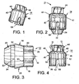
- FIG. 1 is a perspective view of a lug nut cap according to the present invention.
- FIG. 2 illustrates a capped wheel nut assembly constructed and arranged according to the present invention.
- FIG. 3 illustrates the wheel nut shown in FIG. 2.
- FIG. 4 further illustrates the wheel nut cap shown in FIGS. 1 and 2.
- a capped wheel nut assembly 10 comprising a lug or wheel nut 12 and a cap 14 according to one embodiment of the present invention.
- the wheel nut 12 is constructed in the form of an elongated tubular like body 16.
- the body 16 has a main body portion 18 extending from an end 20.
- the main body portion 18 has a polygonal side wall in the form of a six-sided regular polyhedron in which all six outer surfaces or flats 22 are identical and in which the angles between adjacent flats are all equal.
- the flats 22 extend parallel to the longitudinal center line of the tubular body 16.
- the tubular nut body 16 is tapered at the outer end 23 to provide a frusto-conical seat 24 adapted to engage a complementary mating surface.
- the nut body 16 is preferably interiorly threaded through the center of the nut body 16 as is commonly known.
- the nut body 16 has a collar member 28 between the main body portion 18 and the frusto-conical seat 24.
- the collar member 28 includes a stepped portion or shoulder 34 which, as will be further explained below, cooperates with a mating member of the wheel nut cap 14 in the capped wheel nut assembly 10.
- the collar member 28 flares out from the end 30 of main body portion 18 to a juncture 32 with the outer end 23 to further define the stepped or shoulder portion 34.
- the cap 14 is constructed in the form of hollow shell 40 and in the shape of an elongated tubular like body 42 having an upper body portion 44 and a lower body portion 46.
- the upper body portion 44 has a generally cylindrical upper cavity portion 48, which is concentric with a generally cylindrical lower cavity portion 50.
- the upper cavity portion 44 is adapted to house the end of a threaded lug (not shown) that may, in some cases, extend above and through the wheel nut 12 when the wheel nut is installed on an automotive threaded lug.
- the lower cavity portion 50 is constructed and arranged to fit over a substantial portion of the wheel nut 12.
- the lower cavity portion 50 includes an upper cylindrical section 52 that is adapted to fit over the main body portion 18.
- the lower cavity portion 50 further includes a lower cavity section 54 that has a slightly larger diameter than upper cylindrical section 52.
- the lower cavity section 54 terminates in a radially-inwardly flared lip portion 56.
- the length of the lower cavity portion 50 is selected to enable the lip 56 to snap over the annular shoulder 34 on the inner end of collar member 28 when the cap 14 is pressed onto the wheel nut 12.
- the lower cavity section 54 includes four equally spaced relief slots 58 formed through and inwardly of the lip 56.
- the length of the slots 58 is preferably the length of the lower cavity section 54, which length is generally equal to the length of the collar member 28.
- the cap 14 can be made from any number of suitable materials, by virtue of making the cap 14 from a flexible, yet sturdy, plastic material and by adding the relief slots 58, the cap 14 can be constructed and arranged with a large holding force when the lip portion 56 snaps onto the shoulder portion 34 of the collar member 28. Preferably, the holding force is generally too large to allow one to easily and readily twist the cap 14 off the wheel nut 12.
- one of the features of the present invention is to provide a quick and easy means of releasing the grip of lip portion 56 from the collar 28.
- One method of providing this feature is to add an engagement means to the wheel nut 12, such as a pair of diametrically opposite protrusions or cap ramps 60 on the outer end 20 of the main body portion 18, and an associated engagement means to the cap 14, such as a pair of diametrically opposite protrusions or nut ramps 62 in the inner portion of the upper section 52 of the lower cavity portion 50.
- the engagement means 60 is added to the outer end 20 of the main body portion 18 at a position to be in the path of travel of the engagement means 62 inside the cap 14, when the cap 14 is caused to rotate about the nut 12.
- the engagement of the ramping members 60 and 62 will force the lip portion 56 of the cap 14 to move off of the shoulder portion 34 of collar member 28.
- the resilient nature of the lip 56 allows the lip 56, and to some extent a portion of the lower cavity portion 50, to expand and move over the shoulder 34 when the cap 14 is caused to move off of the nut 12.
- the engagement ramps 60 will engage the engagement ramps 62 as the cap 14 is twisted about the nut 12 in either direction, and that upon this engagement the ramps will push the cap 14 from the nut 12 in an upward axial direction. When this axial force is greater than the holding force of the resilient lip portion 56, the lip portion 56 is pulled off of the collar member 28.
- the upper body portion 44 of hollow shell 40 is formed with a polygonal outer side wall 70 in the form of a six-sided regular polyhedron in which all six outer surfaces or flats 72 are identical and in which the angles between adjacent surfaces or flats 72 are equal.
- the flats 72 extend parallel to the longitudinal center line of the hollow shell 40.
- a conventional wrench can be applied over the flats 72 and turned in either direction until the ramping member 62 strikes and moves over the engagement means 60 on the wheel nut 12. This action causes the cap 14 to be cammed off of the wheel nut 12.
- cap 14 is shown and described as having a standard hex shape, the cap 14 can include any number of suitable configurations, such as, for example, a slotted head, to assist in the removal of the cap 14 from the nut 12.
- the engagement means 60 and 62 are shown and described as being ramping means, the engagement means 60 and 62 can be constructed and arranged in any number of different ways in accordance with the principles of the present invention.
- the engagement means can be in the form of single protrusions on the wheel nut and associated cap, or the engagement means could be replaced by any number of well known cam and cam follower devices that would function to push the cap in a generally upward axial direction relative to the wheel nut when it is desirable to remove the cap from the wheel nut.
- the wheel nut 12 and cap 14 have been shown and described to include a particular snap-fit combination, the nut and cap can be constructed and arranged to include other snap-fit assemblies in accordance with the principles of the present invention.
Landscapes
- Engineering & Computer Science (AREA)
- General Engineering & Computer Science (AREA)
- Mechanical Engineering (AREA)
- Dowels (AREA)
- Bolts, Nuts, And Washers (AREA)
Applications Claiming Priority (4)
| Application Number | Priority Date | Filing Date | Title |
|---|---|---|---|
| US37614302P | 2002-04-29 | 2002-04-29 | |
| US376143P | 2002-04-29 | ||
| US391675 | 2003-03-19 | ||
| US10/391,675 US6860692B2 (en) | 2002-04-29 | 2003-03-19 | Nut cap and assembly therewith |
Publications (3)
| Publication Number | Publication Date |
|---|---|
| EP1359332A2 true EP1359332A2 (fr) | 2003-11-05 |
| EP1359332A3 EP1359332A3 (fr) | 2004-01-07 |
| EP1359332B1 EP1359332B1 (fr) | 2006-06-21 |
Family
ID=29219033
Family Applications (1)
| Application Number | Title | Priority Date | Filing Date |
|---|---|---|---|
| EP03008265A Expired - Lifetime EP1359332B1 (fr) | 2002-04-29 | 2003-04-09 | Chapeau d'écrou et ensemble l'incluant |
Country Status (4)
| Country | Link |
|---|---|
| US (1) | US6860692B2 (fr) |
| EP (1) | EP1359332B1 (fr) |
| CA (1) | CA2427179C (fr) |
| DE (1) | DE60306253T2 (fr) |
Families Citing this family (11)
| Publication number | Priority date | Publication date | Assignee | Title |
|---|---|---|---|---|
| GB0024485D0 (en) * | 2000-10-06 | 2000-11-22 | Wheelsure Ltd | Wheel nut assembly |
| US6749386B2 (en) | 2001-08-20 | 2004-06-15 | Maclean-Fogg Company | Locking fastener assembly |
| US7465135B2 (en) | 2003-11-14 | 2008-12-16 | Maclean-Fogg Company | U-Nut fastening assembly |
| US7581913B2 (en) * | 2005-01-25 | 2009-09-01 | Honda Motor Company, Ltd. | Seal nut assembly and method of manufacture |
| USD547172S1 (en) * | 2006-03-09 | 2007-07-24 | Marine And Industrial Enterprises, Ltd | Protective cap |
| US20090057316A1 (en) * | 2007-08-31 | 2009-03-05 | Schweinberg Fred M | Coil nut |
| US8936423B2 (en) | 2011-08-18 | 2015-01-20 | Maclean-Fogg Company | Plastic polymer covered fastener |
| JP5601354B2 (ja) * | 2012-07-25 | 2014-10-08 | 株式会社デンソー | 車両用回転電機のプーリ固定ナット蓋構造 |
| WO2015100407A1 (fr) | 2013-12-27 | 2015-07-02 | Mcgard Llc | Élément de fixation à chapeau décoratif protégé |
| US10745183B2 (en) * | 2017-03-02 | 2020-08-18 | Huffy Corporation | Axle guard for packaging a bicycle |
| USD1086004S1 (en) * | 2024-02-06 | 2025-07-29 | Abram Brunka | Skate wheel nut |
Citations (2)
| Publication number | Priority date | Publication date | Assignee | Title |
|---|---|---|---|---|
| US5163797A (en) | 1991-10-28 | 1992-11-17 | Wheel Masters Inc. | Vehicle lug nut covers |
| US5350266A (en) | 1993-10-22 | 1994-09-27 | Creco Corporation | Plastic capped nut |
Family Cites Families (29)
| Publication number | Priority date | Publication date | Assignee | Title |
|---|---|---|---|---|
| US33806A (en) * | 1861-11-26 | Improvement in fastening window-blinds | ||
| US1249592A (en) * | 1917-03-26 | 1917-12-11 | Edward L Bruhn | Fastening device. |
| US1397235A (en) * | 1921-07-05 | 1921-11-15 | Sabel Sidney Ralph | Dust-cap for automobiles |
| US2103743A (en) | 1935-04-30 | 1937-12-28 | Raymond S Holcomb | Sealed fastening device |
| US3136458A (en) * | 1961-02-27 | 1964-06-09 | Ruetz Karl | Container including a neck with a pouring opening and closing device for the same |
| US3372834A (en) * | 1966-01-24 | 1968-03-12 | Robert A. Ayotte | Container and closure assembly |
| CH565682A5 (fr) | 1973-08-24 | 1975-08-29 | Nestle Sa | |
| US4382635A (en) | 1981-02-13 | 1983-05-10 | General Motors Corporation | Plastic vehicle wheel cover |
| DE3335723C2 (de) | 1983-10-01 | 1986-06-26 | RADOLID Thiel GmbH, 5880 Lüdenscheid | Kunststoffschutzkappe zum Aufklemmen auf eine Mehrkantmutter |
| US4659273A (en) | 1985-11-08 | 1987-04-21 | Trailer Marine Transport | Lug attachment |
| US4786224A (en) | 1986-04-24 | 1988-11-22 | Maron Products, Inc. | Wheel lug nut cover |
| USRE33806E (en) | 1988-01-04 | 1992-01-28 | Simulated custom wheels | |
| US4962968A (en) | 1989-06-05 | 1990-10-16 | Neil Caplin | Skateboard hubcap retrofit assembly |
| US4968202A (en) | 1990-01-16 | 1990-11-06 | Mcgard, Inc. | Decorative and protective cap for locknut |
| US5048898A (en) | 1990-07-06 | 1991-09-17 | Del-Met Corporation | Wheel cover twist fastener system |
| US5082409A (en) | 1990-10-26 | 1992-01-21 | Aluminum Company Of America | Vehicular lug nut cover and clip |
| US5098242A (en) * | 1991-07-10 | 1992-03-24 | Emhart Inc. | Plastic fastener for threaded stud |
| USD350524S (en) | 1992-10-21 | 1994-09-13 | Aluminum Company Of America | Cover for a vehicle wheel lug nut and washer |
| US5340201A (en) | 1993-06-30 | 1994-08-23 | Del-Met Corporation | Snap-on dress wheel simulator |
| US5380070A (en) | 1993-08-09 | 1995-01-10 | Wheel Masters, Inc. | Lug nut covers |
| US5752794A (en) * | 1996-11-04 | 1998-05-19 | Chrysler Corporation | Fastener retention system for a wheel cover of a vehicle |
| US5857818A (en) | 1997-03-04 | 1999-01-12 | Bias, Sr.; Donald R. | Lug nut cover |
| US5810532A (en) | 1997-05-09 | 1998-09-22 | Grand General Accessories Manufacturing Inc. | Vehicle lug nut covers |
| WO2000057069A1 (fr) | 1999-03-22 | 2000-09-28 | Alcoa Inc. | Protection deux pieces destinee a un assemblage boulon-ecrou et collier de serrage associe |
| US6135570A (en) | 1999-04-01 | 2000-10-24 | Mckechnie Vehicle Components (Usa), Inc. | Wheel cover having a one-way locking mechanism and decorative nut caps |
| US6036420A (en) | 1999-09-21 | 2000-03-14 | Horizon Technology, Llp | Capped wheel nut assembly |
| US6273658B1 (en) | 2000-01-27 | 2001-08-14 | S. Allen Patterson | Enclosure for protecting a lug and lug nut |
| US6398471B1 (en) * | 2000-06-15 | 2002-06-04 | Illinois Tool Works Inc. | Utility lug nut tension indicator |
| US6318942B1 (en) * | 2000-08-16 | 2001-11-20 | Mckechnie Vehicle Components (Usa), Inc. | Lug cap having retention detents |
-
2003
- 2003-03-19 US US10/391,675 patent/US6860692B2/en not_active Expired - Fee Related
- 2003-04-09 EP EP03008265A patent/EP1359332B1/fr not_active Expired - Lifetime
- 2003-04-09 DE DE60306253T patent/DE60306253T2/de not_active Expired - Fee Related
- 2003-04-28 CA CA002427179A patent/CA2427179C/fr not_active Expired - Fee Related
Patent Citations (2)
| Publication number | Priority date | Publication date | Assignee | Title |
|---|---|---|---|---|
| US5163797A (en) | 1991-10-28 | 1992-11-17 | Wheel Masters Inc. | Vehicle lug nut covers |
| US5350266A (en) | 1993-10-22 | 1994-09-27 | Creco Corporation | Plastic capped nut |
Also Published As
| Publication number | Publication date |
|---|---|
| CA2427179A1 (fr) | 2003-10-29 |
| EP1359332B1 (fr) | 2006-06-21 |
| US20030202859A1 (en) | 2003-10-30 |
| DE60306253D1 (de) | 2006-08-03 |
| EP1359332A3 (fr) | 2004-01-07 |
| US6860692B2 (en) | 2005-03-01 |
| CA2427179C (fr) | 2008-03-11 |
| DE60306253T2 (de) | 2006-11-02 |
Similar Documents
| Publication | Publication Date | Title |
|---|---|---|
| US6860692B2 (en) | Nut cap and assembly therewith | |
| US5810532A (en) | Vehicle lug nut covers | |
| US5857818A (en) | Lug nut cover | |
| US4764070A (en) | Capped wheel nut assembly | |
| US6036420A (en) | Capped wheel nut assembly | |
| US5924342A (en) | Oil filter wrench | |
| US5575602A (en) | Multiple-armed nut | |
| ATE232267T1 (de) | Mutter mit federvorrichtung | |
| CA2398802A1 (fr) | Plongeur a tampon avec elements d'extremite de blocage monoblocs | |
| US5465858A (en) | Tamper-evident closure | |
| EP0939236B1 (fr) | Ensemble écrou de roue/bouchon à rondelle isolante | |
| US6729822B2 (en) | Fastening having inner deformable hollow element and outer sleeve | |
| US6062788A (en) | Nail | |
| IE59005B1 (en) | Helving device for securing a handle to a tool | |
| US1280646A (en) | Spoke remover and tightener. | |
| US7244085B2 (en) | Fastener assembly | |
| CA2910694A1 (fr) | Indicateurs d'ecrou et dispositifs associes | |
| US2780243A (en) | Plastic valve cap | |
| JPS58170601A (ja) | 車輌とその取付けニツプル | |
| US5803690A (en) | Locking system for vehicle wheels | |
| US20050011319A1 (en) | Sleeve device | |
| US5890861A (en) | Retaining element for multipart connection units such as screw connections and the like | |
| US2816681A (en) | Screw plug cap and method of forming the same | |
| US20190210197A1 (en) | Spark plug installation and removal tool | |
| US10583703B2 (en) | Tire valve cap |
Legal Events
| Date | Code | Title | Description |
|---|---|---|---|
| PUAI | Public reference made under article 153(3) epc to a published international application that has entered the european phase |
Free format text: ORIGINAL CODE: 0009012 |
|
| AK | Designated contracting states |
Kind code of ref document: A2 Designated state(s): AT BE BG CH CY CZ DE DK EE ES FI FR GB GR HU IE IT LI LU MC NL PT RO SE SI SK TR |
|
| AX | Request for extension of the european patent |
Extension state: AL LT LV MK |
|
| PUAL | Search report despatched |
Free format text: ORIGINAL CODE: 0009013 |
|
| AK | Designated contracting states |
Kind code of ref document: A3 Designated state(s): AT BE BG CH CY CZ DE DK EE ES FI FR GB GR HU IE IT LI LU MC NL PT RO SE SI SK TR |
|
| AX | Request for extension of the european patent |
Extension state: AL LT LV MK |
|
| RIC1 | Information provided on ipc code assigned before grant |
Ipc: 7F 16B 37/14 A Ipc: 7B 60B 7/00 B |
|
| 17P | Request for examination filed |
Effective date: 20040521 |
|
| 17Q | First examination report despatched |
Effective date: 20040816 |
|
| AKX | Designation fees paid |
Designated state(s): DE FR GB IT |
|
| GRAP | Despatch of communication of intention to grant a patent |
Free format text: ORIGINAL CODE: EPIDOSNIGR1 |
|
| GRAS | Grant fee paid |
Free format text: ORIGINAL CODE: EPIDOSNIGR3 |
|
| GRAA | (expected) grant |
Free format text: ORIGINAL CODE: 0009210 |
|
| AK | Designated contracting states |
Kind code of ref document: B1 Designated state(s): DE FR GB IT |
|
| PG25 | Lapsed in a contracting state [announced via postgrant information from national office to epo] |
Ref country code: IT Free format text: LAPSE BECAUSE OF FAILURE TO SUBMIT A TRANSLATION OF THE DESCRIPTION OR TO PAY THE FEE WITHIN THE PRESCRIBED TIME-LIMIT;WARNING: LAPSES OF ITALIAN PATENTS WITH EFFECTIVE DATE BEFORE 2007 MAY HAVE OCCURRED AT ANY TIME BEFORE 2007. THE CORRECT EFFECTIVE DATE MAY BE DIFFERENT FROM THE ONE RECORDED. Effective date: 20060621 |
|
| REG | Reference to a national code |
Ref country code: GB Ref legal event code: FG4D |
|
| REF | Corresponds to: |
Ref document number: 60306253 Country of ref document: DE Date of ref document: 20060803 Kind code of ref document: P |
|
| ET | Fr: translation filed | ||
| PLBE | No opposition filed within time limit |
Free format text: ORIGINAL CODE: 0009261 |
|
| STAA | Information on the status of an ep patent application or granted ep patent |
Free format text: STATUS: NO OPPOSITION FILED WITHIN TIME LIMIT |
|
| 26N | No opposition filed |
Effective date: 20070322 |
|
| PG25 | Lapsed in a contracting state [announced via postgrant information from national office to epo] |
Ref country code: DE Free format text: LAPSE BECAUSE OF NON-PAYMENT OF DUE FEES Effective date: 20071101 |
|
| PG25 | Lapsed in a contracting state [announced via postgrant information from national office to epo] |
Ref country code: FR Free format text: LAPSE BECAUSE OF NON-PAYMENT OF DUE FEES Effective date: 20070430 |
|
| PGFP | Annual fee paid to national office [announced via postgrant information from national office to epo] |
Ref country code: IT Payment date: 20100426 Year of fee payment: 8 |
|
| PGFP | Annual fee paid to national office [announced via postgrant information from national office to epo] |
Ref country code: GB Payment date: 20100426 Year of fee payment: 8 |
|
| GBPC | Gb: european patent ceased through non-payment of renewal fee |
Effective date: 20110409 |
|
| PG25 | Lapsed in a contracting state [announced via postgrant information from national office to epo] |
Ref country code: IT Free format text: LAPSE BECAUSE OF NON-PAYMENT OF DUE FEES Effective date: 20110409 Ref country code: GB Free format text: LAPSE BECAUSE OF NON-PAYMENT OF DUE FEES Effective date: 20110409 |