EP1359478A1 - Doppelwirkende Spindel für die Montage von Uhrzeigern - Google Patents
Doppelwirkende Spindel für die Montage von Uhrzeigern Download PDFInfo
- Publication number
- EP1359478A1 EP1359478A1 EP02076702A EP02076702A EP1359478A1 EP 1359478 A1 EP1359478 A1 EP 1359478A1 EP 02076702 A EP02076702 A EP 02076702A EP 02076702 A EP02076702 A EP 02076702A EP 1359478 A1 EP1359478 A1 EP 1359478A1
- Authority
- EP
- European Patent Office
- Prior art keywords
- force
- adjustment means
- compensated
- spindle according
- spring
- Prior art date
- Legal status (The legal status is an assumption and is not a legal conclusion. Google has not performed a legal analysis and makes no representation as to the accuracy of the status listed.)
- Granted
Links
- 230000000694 effects Effects 0.000 title description 4
- 238000006073 displacement reaction Methods 0.000 claims description 8
- 238000009434 installation Methods 0.000 description 4
- 230000000007 visual effect Effects 0.000 description 4
- 238000000034 method Methods 0.000 description 3
- 230000002950 deficient Effects 0.000 description 2
- 230000008569 process Effects 0.000 description 2
- 102100032392 Circadian-associated transcriptional repressor Human genes 0.000 description 1
- 101710130150 Circadian-associated transcriptional repressor Proteins 0.000 description 1
- 238000010276 construction Methods 0.000 description 1
- 230000001419 dependent effect Effects 0.000 description 1
- 230000036449 good health Effects 0.000 description 1
- 238000005259 measurement Methods 0.000 description 1
- 238000012986 modification Methods 0.000 description 1
- 230000004048 modification Effects 0.000 description 1
- 230000036515 potency Effects 0.000 description 1
- 230000008439 repair process Effects 0.000 description 1
- 230000035945 sensitivity Effects 0.000 description 1
- 239000007787 solid Substances 0.000 description 1
Images


Classifications
-
- G—PHYSICS
- G04—HOROLOGY
- G04D—APPARATUS OR TOOLS SPECIALLY DESIGNED FOR MAKING OR MAINTAINING CLOCKS OR WATCHES
- G04D3/00—Watchmakers' or watch-repairers' machines or tools for working materials
- G04D3/04—Devices for placing bearing jewels, bearing sleeves, or the like in position
-
- Y—GENERAL TAGGING OF NEW TECHNOLOGICAL DEVELOPMENTS; GENERAL TAGGING OF CROSS-SECTIONAL TECHNOLOGIES SPANNING OVER SEVERAL SECTIONS OF THE IPC; TECHNICAL SUBJECTS COVERED BY FORMER USPC CROSS-REFERENCE ART COLLECTIONS [XRACs] AND DIGESTS
- Y10—TECHNICAL SUBJECTS COVERED BY FORMER USPC
- Y10T—TECHNICAL SUBJECTS COVERED BY FORMER US CLASSIFICATION
- Y10T29/00—Metal working
- Y10T29/53—Means to assemble or disassemble
- Y10T29/53639—Means to stake watch or clock
Definitions
- the present invention relates to a double-acting compensated spindle for fitting needles, in particular for switching a timepiece movement.
- double effect means the possibility of controlling the minimum force and the force maximum hunting, as will be explained in more detail below.
- Figures 1 and 2 somehow represent the history of the installation hands on a dial, in particular on the dial of a watch movement.
- Reference 4 in FIG. 1 schematically represents the manual process the oldest. After positioning the hole of a needle above its axis a operator flushes it by means of a stick 41. The correct positioning of a hand, parallel to the dial and along the vertical axis, so that the hands do not do not cling to each other and do not rub on the dial, therefore only depends operator experience and skill. This process is still used for very small series or for repairs.
- FIG 2 there is shown a device 5, called “Bergeon stem” well known in the watchmaking field, comprising a frame 6, provided with a plate 7 for receiving a watch movement, said frame 6 supporting a column 8, surmounted by a tool holder vertical 9 in which three different pins 1, 2 and 3 have been placed, the reference 1 corresponding to the spindle according to the invention described in detail below.
- Each pin has at one end a removable cleat 37, 27 or 17 adapted to each type needle, and at the other end a head 38, 28 or 18 on which the force will be exerted hunting.
- Micrometric screws 30, 20, 10 screwed into the tool holder 9 allow the stroke of each spindle to be adjusted.
- the tool holder 9 is pivoted on an axis 8a of column 8 to bring a category of pins 1, 2 or 3 in the axis of the plate 7.
- These pins allow in known manner to drive successively the hour, minute hand and chronograph by means of the cleat 17, and minute, hour and small second hand counters via a bent cleat, offset from the center of the movement.
- These pins are held in the high position by means of springs 12, 22 or 32 arranged between a well of micrometric screws 30, 20 or 10 and heads 38, 28 or 18, or washers underlying 12a or 22a.
- the distance of each cleat 17, 27 or 37, aimed in rods or tubes 11, 21 or 31, relative to the plate 7 is adjusted by means of micrometric screws 10, 20 or 30 of the frame 5.
- the head of each spindle has a push button 18, 28 or 38 on which an operator will exercise pressure to drive out a needle.
- the pin corresponding to reference 2 allows you to visually check the first possibility not to exceed a fixed predetermined maximum force in stages.
- the tube 21 slides in a tube 25 containing a spring (not visible in FIG. 2) compressed by a piston 24 which can be operated from the outside through the push button 28.
- the piston 24 has perpendicular to its axis a pin 24a which can be moved in a opening of the tube 25 to occupy five different positions, that is to say in compressing the spring to define five maximum force values for example by 500gr steps.
- the tube 25 has near its base an oblong hole 26, in which an overflow indicator 29 can move of maximum force.
- the washer 22a must come to bear on the screw micrometric 20 without any displacement of the indicator 29 being observed during this operation.
- Such a brooch available for example from Sandoz Fils & Co (La Chaux-de-Fonds, Switzerland), however, does not allow precise adjustment of the maximum force must not be exceeded, and above all gives no indication of the force minimum that must be reached for proper hunting.
- the present invention therefore aims to overcome the drawbacks of this art anterior by providing a double-acting compensated spindle that allows you to exercise visual control of both maximum and minimum force, which allows also to fine-tune the value of each force.
- the invention relates to a compensated pin with double effect adaptable to a bracket for the installation of needles on a dial by hunting.
- the bracket usually comprises a frame connected by a column to a pivoting tool holder capable of receiving three spindles adjustable in height for the successive installation of the hour, minute and chronograph hands, or the hands of the hour, minute and hand counters small second.
- Each spindle is characterized in that it comprises three parts having visually controllable travel relative to each other.
- Each spindle comprises, at its base a cleat, adapted to each type of needle, screwed into a lower rod which slides in a tubular part of an intermediate cylindrical element whose other end also slides in a tube at the end of which is screwed a head on which will exert a force F.
- a first spring determining for a first force F 1 , placed in the tubular part of the intermediate element, is compressed between the lower rod in which is screwed a first indicator of displacement passing through the wall of the intermediate element through an oblong hole, and a first means of adjusting the spring in tension constituted by a screw and counter-screw device placed inside the intermediate element.
- a second spring determining for a second force F 2 , placed in the upper tube, is compressed between the end of the intermediate element, into which is screwed a second displacement indicator passing through an oblong hole in the upper tube.
- a second adjustment means identical to the first and located at the end of the upper tube.
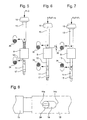
- the spindle shown in Figures 3 and 4 has three main parts: a lower rod 11, one end of which has an internal thread allowing the screwing of a cleat 17 interchangeable for each type of needle, an intermediate cylindrical element 13 and an upper tube 15 on which is screwed a head 18 allowing to exert a force F on the spindle when the latter is adjusted on a bracket 5.
- the lower rod 11 slides in a tubular part 13a of the intermediate cylindrical element 13 with a limited clearance between two extreme positions identified by an indicator member 34 constituted by a screw, screwed into a tapped hole 34a of the solid part of the lower rod 11, and whose head is flush with the external opening of an oblong hole 14 formed through the wall 13a of the intermediate cylindrical element 13.
- the lower rod 11 compresses a helical spring 33, against adjustment means 43 d e the tension of said spring 33, constituted by a screw 43a and a counter-screw 43b whose heads, in the example shown, are accessible by the other end of the intermediate element 13 which then also has a tubular part in the extension of the tubular part 13a.
- adjustment means 43 in the opposite direction so that the heads of the screws and counter-screws 43a, 43b are accessible through the tubular part 13a.
- a small piston 44 interposed between the adjustment means 43 and the spring 44 makes it possible to center said spring. As can be seen more clearly in FIG.
- the indicator 34 occupies in the oblong hole 14 a low position 14a.
- a force F greater than a force F 1 is exerted, depending on the characteristics of the spring 33 and the adjustment made at the level of the adjustment means 43, the indicator 34 will move towards a high position 14b of the oblong hole 14, which therefore makes it possible to exercise a visual check that the force F 1 has been exceeded during the hunting operation.
- the force F 1 corresponds for example to a minimum force which must be exceeded to ensure sufficient tightening of a needle on its axis.
- the specific characteristics of the spring 33 and the adjustment means 43 make it possible, for example, to adjust the minimum force F 1 between 500gr. and 1000gr., preferably between 800gr. and 900gr, according to the specifications of the movement concerned.
- the intermediate element 13 cooperates with the upper tube 15 to define a second force F 2 which will in this case be a maximum force, which may for example be chosen between 1000gr. and 4000gr., preferably between 1500gr. and 3500gr, according to the specifications of the movement concerned.
- the cylindrical element 13 slides in the upper tube 15 with a limited clearance between two extreme positions identified by an indicator member 36 constituted by a screw, screwed into a tapped hole 36a of the intermediate element 13, the head of which is flush with the opening. exterior of an oblong 16 formed through the upper tube 15.
- the intermediate cylindrical element 13 compresses a spring 35 against tension adjustment means 45.
- adjustment means 45 consist of a screw 45a and a counter-screw 45b, the heads of which are accessible through an opening 18a of the head.
- a small centering piston 46 can be interposed between the spring 35 and the adjustment means 45. It is also possible to provide another small centering piston 48 at the other end of the spring.
- the indicator 36 changes from a low position 16a to a high position 16b.
- FIGS. 5, 6 and 7 schematically represent how the compensated double-acting spindle makes it possible to exert a visual check on the minimum driving force F 1 and on the maximum driving force F 2 .
- a force F is exerted on the head 18 until the cleat is brought into contact with the needle concerned.
Landscapes
- Physics & Mathematics (AREA)
- General Physics & Mathematics (AREA)
- Electromechanical Clocks (AREA)
- Measuring Fluid Pressure (AREA)
- Details Of Spanners, Wrenches, And Screw Drivers And Accessories (AREA)
- Force Measurement Appropriate To Specific Purposes (AREA)
- Dental Tools And Instruments Or Auxiliary Dental Instruments (AREA)
Priority Applications (5)
| Application Number | Priority Date | Filing Date | Title |
|---|---|---|---|
| AT02076702T ATE322035T1 (de) | 2002-04-30 | 2002-04-30 | Doppelwirkende spindel für die montage von uhrzeigern |
| EP02076702A EP1359478B1 (de) | 2002-04-30 | 2002-04-30 | Doppelwirkende Spindel für die Montage von Uhrzeigern |
| DE60210197T DE60210197T2 (de) | 2002-04-30 | 2002-04-30 | Doppelwirkende Spindel für die Montage von Uhrzeigern |
| JP2003123416A JP2004004062A (ja) | 2002-04-30 | 2003-04-28 | 時計針を取り付けるための二重効果補正工具 |
| US10/424,905 US6789300B2 (en) | 2002-04-30 | 2003-04-29 | Dual effect compensating tool for fitting hands |
Applications Claiming Priority (1)
| Application Number | Priority Date | Filing Date | Title |
|---|---|---|---|
| EP02076702A EP1359478B1 (de) | 2002-04-30 | 2002-04-30 | Doppelwirkende Spindel für die Montage von Uhrzeigern |
Publications (2)
| Publication Number | Publication Date |
|---|---|
| EP1359478A1 true EP1359478A1 (de) | 2003-11-05 |
| EP1359478B1 EP1359478B1 (de) | 2006-03-29 |
Family
ID=28799709
Family Applications (1)
| Application Number | Title | Priority Date | Filing Date |
|---|---|---|---|
| EP02076702A Expired - Lifetime EP1359478B1 (de) | 2002-04-30 | 2002-04-30 | Doppelwirkende Spindel für die Montage von Uhrzeigern |
Country Status (5)
| Country | Link |
|---|---|
| US (1) | US6789300B2 (de) |
| EP (1) | EP1359478B1 (de) |
| JP (1) | JP2004004062A (de) |
| AT (1) | ATE322035T1 (de) |
| DE (1) | DE60210197T2 (de) |
Families Citing this family (7)
| Publication number | Priority date | Publication date | Assignee | Title |
|---|---|---|---|---|
| US9956677B2 (en) * | 2013-05-08 | 2018-05-01 | Black & Decker Inc. | Power tool with interchangeable power heads |
| DE102016002056A1 (de) * | 2015-08-27 | 2017-03-02 | Ehrt Maschinenbau Gmbh | Antriebseinheit |
| US20180056496A1 (en) * | 2016-08-26 | 2018-03-01 | Robert Bosch Tool Corporation | Modular Handheld Power Tool |
| CN107608199B (zh) * | 2017-10-25 | 2022-11-15 | 深圳市佳马钟表有限公司 | 一种手表指针安装工具 |
| CN111290254B (zh) * | 2020-03-20 | 2024-09-17 | 江苏创源电子有限公司 | 一种拆解装置及拆解方法 |
| CN111352334B (zh) * | 2020-04-11 | 2025-03-25 | 深圳市协鼎兴自动化设备有限公司 | 一种全自动装针机 |
| CN113579686B (zh) * | 2021-07-27 | 2022-06-24 | 新文兴科技(深圳)有限公司 | 一种表带组装装置 |
Citations (2)
| Publication number | Priority date | Publication date | Assignee | Title |
|---|---|---|---|---|
| CH128510A (fr) * | 1927-09-07 | 1928-11-01 | Zenith Montres | Procédé pour poser des éléments tels que des pieds, des piliers etc. de pièces telles que des platines, des ponts etc. utilisées en horlogerie et autres industries, et machine pour la mise en oeuvre de ce procédé. |
| CH283492A (fr) * | 1948-11-15 | 1952-06-15 | Imoberdorf Josef | Machine à poser des pieds, goupilles et autres éléments analogues dans les trous respectifs d'un support. |
Family Cites Families (4)
| Publication number | Priority date | Publication date | Assignee | Title |
|---|---|---|---|---|
| US829309A (en) * | 1906-01-25 | 1906-08-21 | American Railway Signal Company | Automatic railway block-signal. |
| US837577A (en) * | 1906-05-21 | 1906-12-04 | Kendrick And Davis | Watch-roller remover. |
| US2421310A (en) * | 1942-05-02 | 1947-05-27 | William E Berlincourt | Watchmaker's staking tool and jewel setter |
| US2613434A (en) * | 1949-11-07 | 1952-10-14 | George O Martin | Combination staking tool |
-
2002
- 2002-04-30 DE DE60210197T patent/DE60210197T2/de not_active Expired - Lifetime
- 2002-04-30 EP EP02076702A patent/EP1359478B1/de not_active Expired - Lifetime
- 2002-04-30 AT AT02076702T patent/ATE322035T1/de not_active IP Right Cessation
-
2003
- 2003-04-28 JP JP2003123416A patent/JP2004004062A/ja active Pending
- 2003-04-29 US US10/424,905 patent/US6789300B2/en not_active Expired - Fee Related
Patent Citations (2)
| Publication number | Priority date | Publication date | Assignee | Title |
|---|---|---|---|---|
| CH128510A (fr) * | 1927-09-07 | 1928-11-01 | Zenith Montres | Procédé pour poser des éléments tels que des pieds, des piliers etc. de pièces telles que des platines, des ponts etc. utilisées en horlogerie et autres industries, et machine pour la mise en oeuvre de ce procédé. |
| CH283492A (fr) * | 1948-11-15 | 1952-06-15 | Imoberdorf Josef | Machine à poser des pieds, goupilles et autres éléments analogues dans les trous respectifs d'un support. |
Also Published As
| Publication number | Publication date |
|---|---|
| EP1359478B1 (de) | 2006-03-29 |
| ATE322035T1 (de) | 2006-04-15 |
| DE60210197D1 (de) | 2006-05-18 |
| US20030200640A1 (en) | 2003-10-30 |
| US6789300B2 (en) | 2004-09-14 |
| JP2004004062A (ja) | 2004-01-08 |
| DE60210197T2 (de) | 2006-12-28 |
Similar Documents
| Publication | Publication Date | Title |
|---|---|---|
| EP1359478B1 (de) | Doppelwirkende Spindel für die Montage von Uhrzeigern | |
| EP3637197A1 (de) | Vorrichtung zur regulierung der retrograden anzeige einer uhr | |
| CH690047A5 (fr) | Pièce d'horlogerie à affichage rétrograde des minutes, notamment montre-bracelet. | |
| EP0987609A1 (de) | Jährlicher Kalendermechanismus für Uhrwerk | |
| EP1024416A2 (de) | Chronograph | |
| WO1987001797A1 (fr) | Micrometre a affichage numerique | |
| EP3485333A1 (de) | Mechanismus zur auswahl und betätigung von funktionen eines uhrwerks | |
| CH710320A2 (fr) | Piece d'horlogerie comportant une source d'énergie mécanique et un organe de commande. | |
| CH697433B1 (fr) | Pièce d'horlogerie avec mécanisme chronographe. | |
| EP1873696B1 (de) | Mechanischer Golf Zähler | |
| EP1797481B1 (de) | Mechanische oder automatische uhr mit einer einrichtung zur anzeige der zeitgenauigkeit der uhr | |
| EP2249215B1 (de) | Chronographuhr mit sofortiger anzeige von sekunden-bruchteilen | |
| EP0360693B1 (de) | Vorrichtung zur Messung der Festigkeit eines verformbaren Gegenstandes | |
| CH713437A2 (fr) | Mécanisme d'affichage sautant. | |
| EP2802945A1 (de) | Uhrwerkbewegungsanzeigemechanismus, der in abhängigkeit von einer informationsanfrage funktioniert | |
| EP1708052A1 (de) | Uhrwerk | |
| EP2104009A2 (de) | Tiefenmessvorrichtung für Armbanduhren und Armbanduhren, die mit einer solchen Messvorrichtung ausgestattet sind | |
| EP4092491B1 (de) | Uhrwerk mit kupplung | |
| EP4711863A1 (de) | Vorrichtung zur einstellung des gangs einer uhr | |
| CH713388B1 (fr) | Pièce d'horlogerie comprenant un mécanisme de chronographe et un système d'affichage supplémentaire. | |
| CH706080B1 (fr) | Pièce d'horlogerie comportant un mécanisme de sonnerie. | |
| EP1791041A1 (de) | Uhrwerk | |
| CH722147A2 (fr) | Pièce d'horlogerie comprenant un dispositif de réglage de la marche actionnable depuis l'extérieur | |
| CH208214A (fr) | Montre à chronographe. | |
| FR2520509A1 (fr) | Dispositif d'analyse automatique par ultrasons des defauts des soudures |
Legal Events
| Date | Code | Title | Description |
|---|---|---|---|
| PUAI | Public reference made under article 153(3) epc to a published international application that has entered the european phase |
Free format text: ORIGINAL CODE: 0009012 |
|
| AK | Designated contracting states |
Kind code of ref document: A1 Designated state(s): AT BE CH CY DE DK ES FI FR GB GR IE IT LI LU MC NL PT SE TR |
|
| AX | Request for extension of the european patent |
Extension state: AL LT LV MK RO SI |
|
| 17P | Request for examination filed |
Effective date: 20040506 |
|
| AKX | Designation fees paid |
Designated state(s): AT BE CH CY DE DK ES FI FR GB GR IE IT LI LU MC NL PT SE TR |
|
| RAP1 | Party data changed (applicant data changed or rights of an application transferred) |
Owner name: MONTRES BREGUET S.A. |
|
| GRAP | Despatch of communication of intention to grant a patent |
Free format text: ORIGINAL CODE: EPIDOSNIGR1 |
|
| GRAS | Grant fee paid |
Free format text: ORIGINAL CODE: EPIDOSNIGR3 |
|
| GRAA | (expected) grant |
Free format text: ORIGINAL CODE: 0009210 |
|
| AK | Designated contracting states |
Kind code of ref document: B1 Designated state(s): AT BE CH CY DE DK ES FI FR GB GR IE IT LI LU MC NL PT SE TR |
|
| PG25 | Lapsed in a contracting state [announced via postgrant information from national office to epo] |
Ref country code: NL Free format text: LAPSE BECAUSE OF FAILURE TO SUBMIT A TRANSLATION OF THE DESCRIPTION OR TO PAY THE FEE WITHIN THE PRESCRIBED TIME-LIMIT Effective date: 20060329 Ref country code: IE Free format text: LAPSE BECAUSE OF FAILURE TO SUBMIT A TRANSLATION OF THE DESCRIPTION OR TO PAY THE FEE WITHIN THE PRESCRIBED TIME-LIMIT Effective date: 20060329 Ref country code: IT Free format text: LAPSE BECAUSE OF FAILURE TO SUBMIT A TRANSLATION OF THE DESCRIPTION OR TO PAY THE FEE WITHIN THE PRESCRIBED TIME-LIMIT;WARNING: LAPSES OF ITALIAN PATENTS WITH EFFECTIVE DATE BEFORE 2007 MAY HAVE OCCURRED AT ANY TIME BEFORE 2007. THE CORRECT EFFECTIVE DATE MAY BE DIFFERENT FROM THE ONE RECORDED. Effective date: 20060329 Ref country code: GB Free format text: LAPSE BECAUSE OF FAILURE TO SUBMIT A TRANSLATION OF THE DESCRIPTION OR TO PAY THE FEE WITHIN THE PRESCRIBED TIME-LIMIT Effective date: 20060329 Ref country code: AT Free format text: LAPSE BECAUSE OF FAILURE TO SUBMIT A TRANSLATION OF THE DESCRIPTION OR TO PAY THE FEE WITHIN THE PRESCRIBED TIME-LIMIT Effective date: 20060329 |
|
| REG | Reference to a national code |
Ref country code: GB Ref legal event code: FG4D Free format text: NOT ENGLISH |
|
| REG | Reference to a national code |
Ref country code: CH Ref legal event code: EP |
|
| PG25 | Lapsed in a contracting state [announced via postgrant information from national office to epo] |
Ref country code: MC Free format text: LAPSE BECAUSE OF NON-PAYMENT OF DUE FEES Effective date: 20060430 Ref country code: BE Free format text: LAPSE BECAUSE OF NON-PAYMENT OF DUE FEES Effective date: 20060430 |
|
| REG | Reference to a national code |
Ref country code: IE Ref legal event code: FG4D Free format text: LANGUAGE OF EP DOCUMENT: FRENCH |
|
| REF | Corresponds to: |
Ref document number: 60210197 Country of ref document: DE Date of ref document: 20060518 Kind code of ref document: P |
|
| PG25 | Lapsed in a contracting state [announced via postgrant information from national office to epo] |
Ref country code: DK Free format text: LAPSE BECAUSE OF FAILURE TO SUBMIT A TRANSLATION OF THE DESCRIPTION OR TO PAY THE FEE WITHIN THE PRESCRIBED TIME-LIMIT Effective date: 20060629 Ref country code: SE Free format text: LAPSE BECAUSE OF FAILURE TO SUBMIT A TRANSLATION OF THE DESCRIPTION OR TO PAY THE FEE WITHIN THE PRESCRIBED TIME-LIMIT Effective date: 20060629 |
|
| PG25 | Lapsed in a contracting state [announced via postgrant information from national office to epo] |
Ref country code: ES Free format text: LAPSE BECAUSE OF FAILURE TO SUBMIT A TRANSLATION OF THE DESCRIPTION OR TO PAY THE FEE WITHIN THE PRESCRIBED TIME-LIMIT Effective date: 20060710 |
|
| REG | Reference to a national code |
Ref country code: CH Ref legal event code: NV Representative=s name: ICB INGENIEURS CONSEILS EN BREVETS SA |
|
| PG25 | Lapsed in a contracting state [announced via postgrant information from national office to epo] |
Ref country code: PT Free format text: LAPSE BECAUSE OF FAILURE TO SUBMIT A TRANSLATION OF THE DESCRIPTION OR TO PAY THE FEE WITHIN THE PRESCRIBED TIME-LIMIT Effective date: 20060829 |
|
| NLV1 | Nl: lapsed or annulled due to failure to fulfill the requirements of art. 29p and 29m of the patents act | ||
| GBV | Gb: ep patent (uk) treated as always having been void in accordance with gb section 77(7)/1977 [no translation filed] |
Effective date: 20060329 |
|
| REG | Reference to a national code |
Ref country code: IE Ref legal event code: FD4D |
|
| PLBE | No opposition filed within time limit |
Free format text: ORIGINAL CODE: 0009261 |
|
| STAA | Information on the status of an ep patent application or granted ep patent |
Free format text: STATUS: NO OPPOSITION FILED WITHIN TIME LIMIT |
|
| 26N | No opposition filed |
Effective date: 20070102 |
|
| BERE | Be: lapsed |
Owner name: MONTRES BREGUET S.A. Effective date: 20060430 |
|
| PG25 | Lapsed in a contracting state [announced via postgrant information from national office to epo] |
Ref country code: GR Free format text: LAPSE BECAUSE OF FAILURE TO SUBMIT A TRANSLATION OF THE DESCRIPTION OR TO PAY THE FEE WITHIN THE PRESCRIBED TIME-LIMIT Effective date: 20060630 |
|
| PG25 | Lapsed in a contracting state [announced via postgrant information from national office to epo] |
Ref country code: FI Free format text: LAPSE BECAUSE OF FAILURE TO SUBMIT A TRANSLATION OF THE DESCRIPTION OR TO PAY THE FEE WITHIN THE PRESCRIBED TIME-LIMIT Effective date: 20060329 |
|
| PG25 | Lapsed in a contracting state [announced via postgrant information from national office to epo] |
Ref country code: LU Free format text: LAPSE BECAUSE OF NON-PAYMENT OF DUE FEES Effective date: 20060430 Ref country code: TR Free format text: LAPSE BECAUSE OF FAILURE TO SUBMIT A TRANSLATION OF THE DESCRIPTION OR TO PAY THE FEE WITHIN THE PRESCRIBED TIME-LIMIT Effective date: 20060329 |
|
| PG25 | Lapsed in a contracting state [announced via postgrant information from national office to epo] |
Ref country code: CY Free format text: LAPSE BECAUSE OF FAILURE TO SUBMIT A TRANSLATION OF THE DESCRIPTION OR TO PAY THE FEE WITHIN THE PRESCRIBED TIME-LIMIT Effective date: 20060329 |
|
| REG | Reference to a national code |
Ref country code: FR Ref legal event code: PLFP Year of fee payment: 15 |
|
| REG | Reference to a national code |
Ref country code: FR Ref legal event code: PLFP Year of fee payment: 16 |
|
| REG | Reference to a national code |
Ref country code: FR Ref legal event code: PLFP Year of fee payment: 17 |
|
| PGFP | Annual fee paid to national office [announced via postgrant information from national office to epo] |
Ref country code: FR Payment date: 20210323 Year of fee payment: 20 Ref country code: CH Payment date: 20210326 Year of fee payment: 20 |
|
| PGFP | Annual fee paid to national office [announced via postgrant information from national office to epo] |
Ref country code: DE Payment date: 20210323 Year of fee payment: 20 |
|
| REG | Reference to a national code |
Ref country code: DE Ref legal event code: R071 Ref document number: 60210197 Country of ref document: DE |
|
| REG | Reference to a national code |
Ref country code: CH Ref legal event code: PL |