EP1359574A2 - Système optique d'enregistrement / de reproduction, lentille d'objectif et élément optique de correction d'aberration - Google Patents
Système optique d'enregistrement / de reproduction, lentille d'objectif et élément optique de correction d'aberration Download PDFInfo
- Publication number
- EP1359574A2 EP1359574A2 EP03252541A EP03252541A EP1359574A2 EP 1359574 A2 EP1359574 A2 EP 1359574A2 EP 03252541 A EP03252541 A EP 03252541A EP 03252541 A EP03252541 A EP 03252541A EP 1359574 A2 EP1359574 A2 EP 1359574A2
- Authority
- EP
- European Patent Office
- Prior art keywords
- objective lens
- wavelength
- lens
- diffractive
- optical
- Prior art date
- Legal status (The legal status is an assumption and is not a legal conclusion. Google has not performed a legal analysis and makes no representation as to the accuracy of the status listed.)
- Withdrawn
Links
- 230000003287 optical effect Effects 0.000 title claims abstract description 736
- 230000004075 alteration Effects 0.000 title claims abstract description 331
- 230000008859 change Effects 0.000 claims abstract description 123
- 230000004907 flux Effects 0.000 claims description 229
- 230000008878 coupling Effects 0.000 claims description 107
- 238000010168 coupling process Methods 0.000 claims description 107
- 238000005859 coupling reaction Methods 0.000 claims description 107
- 239000011241 protective layer Substances 0.000 claims description 61
- 239000011521 glass Substances 0.000 claims description 7
- 238000000034 method Methods 0.000 claims description 5
- 238000010894 electron beam technology Methods 0.000 claims 4
- 239000004065 semiconductor Substances 0.000 description 168
- 230000014509 gene expression Effects 0.000 description 57
- 239000000203 mixture Substances 0.000 description 45
- 235000005811 Viola adunca Nutrition 0.000 description 26
- 235000013487 Viola odorata Nutrition 0.000 description 26
- 235000002254 Viola papilionacea Nutrition 0.000 description 26
- 244000154870 Viola adunca Species 0.000 description 25
- 230000003247 decreasing effect Effects 0.000 description 23
- 238000012937 correction Methods 0.000 description 21
- 244000172533 Viola sororia Species 0.000 description 13
- 238000004519 manufacturing process Methods 0.000 description 11
- 238000000465 moulding Methods 0.000 description 8
- 238000005516 engineering process Methods 0.000 description 7
- 230000007613 environmental effect Effects 0.000 description 7
- 230000009471 action Effects 0.000 description 6
- 230000010355 oscillation Effects 0.000 description 6
- 210000001747 pupil Anatomy 0.000 description 6
- 230000005855 radiation Effects 0.000 description 6
- 230000009467 reduction Effects 0.000 description 6
- 201000009310 astigmatism Diseases 0.000 description 5
- 238000013461 design Methods 0.000 description 4
- 238000010422 painting Methods 0.000 description 4
- 230000000630 rising effect Effects 0.000 description 4
- 241000511976 Hoya Species 0.000 description 3
- 239000000463 material Substances 0.000 description 2
- 101000674742 Homo sapiens Transcription initiation factor TFIID subunit 5 Proteins 0.000 description 1
- 241001025261 Neoraja caerulea Species 0.000 description 1
- 102100021230 Transcription initiation factor TFIID subunit 5 Human genes 0.000 description 1
- 240000009038 Viola odorata Species 0.000 description 1
- ZCCIPPOKBCJFDN-UHFFFAOYSA-N calcium nitrate Chemical compound [Ca+2].[O-][N+]([O-])=O.[O-][N+]([O-])=O ZCCIPPOKBCJFDN-UHFFFAOYSA-N 0.000 description 1
- 230000007423 decrease Effects 0.000 description 1
- 238000001514 detection method Methods 0.000 description 1
- 238000011161 development Methods 0.000 description 1
- 239000006185 dispersion Substances 0.000 description 1
- 230000000694 effects Effects 0.000 description 1
- 238000011835 investigation Methods 0.000 description 1
- FGIUAXJPYTZDNR-UHFFFAOYSA-N potassium nitrate Inorganic materials [K+].[O-][N+]([O-])=O FGIUAXJPYTZDNR-UHFFFAOYSA-N 0.000 description 1
- 235000010333 potassium nitrate Nutrition 0.000 description 1
- 230000008569 process Effects 0.000 description 1
- 238000012545 processing Methods 0.000 description 1
- 230000035945 sensitivity Effects 0.000 description 1
- 238000007493 shaping process Methods 0.000 description 1
- 239000000758 substrate Substances 0.000 description 1
Images


Classifications
-
- G—PHYSICS
- G11—INFORMATION STORAGE
- G11B—INFORMATION STORAGE BASED ON RELATIVE MOVEMENT BETWEEN RECORD CARRIER AND TRANSDUCER
- G11B7/00—Recording or reproducing by optical means, e.g. recording using a thermal beam of optical radiation by modifying optical properties or the physical structure, reproducing using an optical beam at lower power by sensing optical properties; Record carriers therefor
- G11B7/12—Heads, e.g. forming of the optical beam spot or modulation of the optical beam
- G11B7/135—Means for guiding the beam from the source to the record carrier or from the record carrier to the detector
- G11B7/1372—Lenses
- G11B7/1376—Collimator lenses
-
- G—PHYSICS
- G02—OPTICS
- G02B—OPTICAL ELEMENTS, SYSTEMS OR APPARATUS
- G02B13/00—Optical objectives specially designed for the purposes specified below
- G02B13/18—Optical objectives specially designed for the purposes specified below with lenses having one or more non-spherical faces, e.g. for reducing geometrical aberration
-
- G—PHYSICS
- G11—INFORMATION STORAGE
- G11B—INFORMATION STORAGE BASED ON RELATIVE MOVEMENT BETWEEN RECORD CARRIER AND TRANSDUCER
- G11B7/00—Recording or reproducing by optical means, e.g. recording using a thermal beam of optical radiation by modifying optical properties or the physical structure, reproducing using an optical beam at lower power by sensing optical properties; Record carriers therefor
- G11B7/12—Heads, e.g. forming of the optical beam spot or modulation of the optical beam
- G11B7/135—Means for guiding the beam from the source to the record carrier or from the record carrier to the detector
- G11B7/1353—Diffractive elements, e.g. holograms or gratings
-
- G—PHYSICS
- G11—INFORMATION STORAGE
- G11B—INFORMATION STORAGE BASED ON RELATIVE MOVEMENT BETWEEN RECORD CARRIER AND TRANSDUCER
- G11B7/00—Recording or reproducing by optical means, e.g. recording using a thermal beam of optical radiation by modifying optical properties or the physical structure, reproducing using an optical beam at lower power by sensing optical properties; Record carriers therefor
- G11B7/12—Heads, e.g. forming of the optical beam spot or modulation of the optical beam
- G11B7/135—Means for guiding the beam from the source to the record carrier or from the record carrier to the detector
- G11B7/1372—Lenses
- G11B7/1374—Objective lenses
-
- G—PHYSICS
- G11—INFORMATION STORAGE
- G11B—INFORMATION STORAGE BASED ON RELATIVE MOVEMENT BETWEEN RECORD CARRIER AND TRANSDUCER
- G11B7/00—Recording or reproducing by optical means, e.g. recording using a thermal beam of optical radiation by modifying optical properties or the physical structure, reproducing using an optical beam at lower power by sensing optical properties; Record carriers therefor
- G11B7/12—Heads, e.g. forming of the optical beam spot or modulation of the optical beam
- G11B7/135—Means for guiding the beam from the source to the record carrier or from the record carrier to the detector
- G11B7/1372—Lenses
- G11B7/1378—Separate aberration correction lenses; Cylindrical lenses to generate astigmatism; Beam expanders
-
- G—PHYSICS
- G11—INFORMATION STORAGE
- G11B—INFORMATION STORAGE BASED ON RELATIVE MOVEMENT BETWEEN RECORD CARRIER AND TRANSDUCER
- G11B7/00—Recording or reproducing by optical means, e.g. recording using a thermal beam of optical radiation by modifying optical properties or the physical structure, reproducing using an optical beam at lower power by sensing optical properties; Record carriers therefor
- G11B7/12—Heads, e.g. forming of the optical beam spot or modulation of the optical beam
- G11B7/135—Means for guiding the beam from the source to the record carrier or from the record carrier to the detector
- G11B7/1392—Means for controlling the beam wavefront, e.g. for correction of aberration
- G11B7/13922—Means for controlling the beam wavefront, e.g. for correction of aberration passive
-
- G—PHYSICS
- G11—INFORMATION STORAGE
- G11B—INFORMATION STORAGE BASED ON RELATIVE MOVEMENT BETWEEN RECORD CARRIER AND TRANSDUCER
- G11B7/00—Recording or reproducing by optical means, e.g. recording using a thermal beam of optical radiation by modifying optical properties or the physical structure, reproducing using an optical beam at lower power by sensing optical properties; Record carriers therefor
- G11B7/12—Heads, e.g. forming of the optical beam spot or modulation of the optical beam
- G11B7/135—Means for guiding the beam from the source to the record carrier or from the record carrier to the detector
- G11B7/1392—Means for controlling the beam wavefront, e.g. for correction of aberration
- G11B7/13925—Means for controlling the beam wavefront, e.g. for correction of aberration active, e.g. controlled by electrical or mechanical means
-
- G—PHYSICS
- G11—INFORMATION STORAGE
- G11B—INFORMATION STORAGE BASED ON RELATIVE MOVEMENT BETWEEN RECORD CARRIER AND TRANSDUCER
- G11B7/00—Recording or reproducing by optical means, e.g. recording using a thermal beam of optical radiation by modifying optical properties or the physical structure, reproducing using an optical beam at lower power by sensing optical properties; Record carriers therefor
- G11B2007/0003—Recording, reproducing or erasing systems characterised by the structure or type of the carrier
- G11B2007/0006—Recording, reproducing or erasing systems characterised by the structure or type of the carrier adapted for scanning different types of carrier, e.g. CD & DVD
-
- G—PHYSICS
- G11—INFORMATION STORAGE
- G11B—INFORMATION STORAGE BASED ON RELATIVE MOVEMENT BETWEEN RECORD CARRIER AND TRANSDUCER
- G11B7/00—Recording or reproducing by optical means, e.g. recording using a thermal beam of optical radiation by modifying optical properties or the physical structure, reproducing using an optical beam at lower power by sensing optical properties; Record carriers therefor
- G11B7/12—Heads, e.g. forming of the optical beam spot or modulation of the optical beam
- G11B7/135—Means for guiding the beam from the source to the record carrier or from the record carrier to the detector
- G11B7/1372—Lenses
- G11B2007/13727—Compound lenses, i.e. two or more lenses co-operating to perform a function, e.g. compound objective lens including a solid immersion lens, positive and negative lenses either bonded together or with adjustable spacing
Definitions
- the present invention relates to a recording reproducing optical system by which at least one of recording and reproducing of the information is conducted onto an optical information recording medium, objective lens, aberration correcting optical element, optical pick-up apparatus and recording reproducing apparatus.
- high density optical disk system in which a blue violet semiconductor laser light source of about 400 nm wavelength, and an objective lens whose numerical aperture (NA) is heightened to about 0.85, are used, is advanced.
- NA numerical aperture
- an optical disk of NA 0.85 and using wavelength 400 nm hereinafter, in the present specification, called "high density DVD"
- the information of 20 - 30 CB can be recorded.
- the objective lens of two lenses in two groups composition disclosed in Japanese Tokkaihei No. 10-123410 is publicly known.
- This objective lens is a lens in which, by dividing the refractive force of the optical surface to the ray of light of the high NA into 4 surfaces, the production error sensitivity of each lens is decreased, however, there is a problem that the production cost is increased by the amount in which a process is necessary by which each lens is assembled. From the view point of the production cost, also in such a high density DVD system, as in the CD system or DVD system, it is desired that the objective lens is structured by one lens in one group composition. Then, for the more cost reduction, it is more desirable that the objective lens for the high density DVD system is a plastic lens.
- the plastic objective lens appropriate for the high density DVD system one of inventors of the present invention proposed, together with another inventor, an objective lens as described in Japanese Tokkai No. 2001-324673.
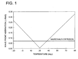
- the plastic lens of NA of about 0.85 when the environmental temperature changes, the change of the wave front aberration which is generated due to the change of the refractive index of the plastic is large, it is a problem in the practical use.
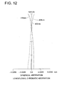
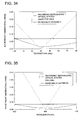
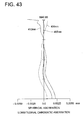
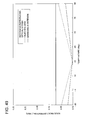
- Fig. 1 as an example, the situation of the wave front aberration change of the plastic lens of one lens in one group composition whose NA is 0.85, focal distance is 2.2 mm, and designed reference wavelength is 405 nm to the temperature change, is shown. From Fig. 1, in the plastic lens of NA of 0.85, because the wave front aberration exceeds the Marechal's criterion at the temperature change of ⁇ 15 °C, it can not be used for the objective lens of the optical disk player in the state as it is.
- One of the present inventors proposes, as an optical pick-up apparatus for correcting the change of the wave front aberration due to the temperature change of the high NA plastic objective lens, the optical pick-up apparatus as described in Japanese Tokkai No. 2002-08228.
- an object of the present invention is, in a recording reproducing optical system of the optical disk which uses a plastic objective lens of the high NA one lens in one group composition, to provide the recording reproducing optical system which can compensate the change of the wave front aberration due to the temperature change of the objective lens.
- the object of the present invention is to provide the recording reproducing optical system in which it is not necessary that the change of the wave front aberration due to the temperature change of the objective lens is dynamically detected, and which can be produced at low cost.
- the object of the present invention is to provide an optical pick-up apparatus of the optical disk on which this recording reproducing optical system is mounted, and a recording reproducing apparatus of the optical disk on which this optical pick-up apparatus is mounted.
- the object of the present invention is also to provide an objective lens and an aberration correcting optical element which are appropriate for the recording reproducing optical system which can compensate the change of the wave front aberration due to the temperature change of the plastic objective lens of the high NA one lens in one group composition.
- the first recording reproducing optical system is characterized in that: in a recording reproducing optical system which conducts the recording of the information and/or reproducing of the information, onto an optical information recording medium, including a light source, an objective lens which converges the light flux emitted from the light source onto the information recording surface of the optical information recording medium, and an aberration correcting optical element located in an optical path between the light source and the objective lens, the objective lens is a plastic lens of one lens in one group composition having at least one surface of the aspheric surface, and at least one diffractive surface on which a diffractive structure formed of a plurality of concentric ring-shaped zone step differences is formed; and the aberration correcting optical system has at least one plastic lens in which the diffractive structure formed of a plurality of concentric ring-shaped zone step differences is formed on at least one surface, and satisfies the following expressions (1), (2) and (3).
- PR2 is the refracting power (mm -1 ) as the refractive lens of the plastic lens of the aberration correcting optical element.
- the first recording reproducing optical system according to the present invention is, to cancel the change of the spherical aberration due to the change of the temperature, provided with an aberration correcting optical element having the plastic lens having a positive refracting power which is located in the optical path between the light source and an objective lens which is one lens in one group composition plastic lens and which satisfies expression (3).
- the inclination angle of the upper marginal ray of the light flux emitted from the aberration correcting optical element changes, when the plastic lens included in the aberration correcting optical element satisfies the expression (3), to the direction in which the lateral magnification of the objective lens decreases.
- the lateral magnification of the objective lens is decreased, because the spherical aberration in the under correction direction is generated, the spherical aberration of the objective lens changed to the over correction direction due to the refractive index change can be cancelled.
- the diffractive structure formed of a plurality of the concentric ring-shaped zone step differences is formed on at least one surface of the plastic lens of the aberration correcting optical element, and its diffracting power is made to satisfy the expression (2).
- the changed amount of the inclination angle of the upper marginal ray of the light flux emitted from the aberration correcting optical element can be arbitrarily selected.
- the PR2 in the expression (3) is a total sum of the refracting power of all plastic lenses included in the aberration correcting optical element
- the aberration correcting optical element is structured in such a manner that at least one plastic lens of the plastic lenses included in the aberration correcting optical element has at least one diffractive surface.
- the PD2 in the expression (2) is a total sum of the diffracting powers of all diffractive surfaces formed on the plastic lens included in the aberration correcting optical element.
- the longitudinal chromatic aberration generated in the optical system is a problem.
- the laser light emitted from the semiconductor laser is generally a single wavelength (single mode) and the longitudinal chromatic aberration is not generated, in practice, there is a case where the mode hopping in which the central wavelength is hopped instantly by several nms, occurs due to the temperature change or output change.
- the change of the wavelength by the mode hopping is several nms which is very small, when the blue violet semiconductor laser whose wavelength is about 400 nm and short, is used, even when it is a very small change of the wavelength by the mode hopping, the longitudinal chromatic aberration generated in the objective lens is a large amount. This is, in the wavelength range of 400 nm, for the reason that the dispersion of the optical material becomes very large. Accordingly, when the blue violet semiconductor laser is used for the light source, it is necessary that the longitudinal chromatic aberration of the optical system is corrected.
- the diffracting power of the plastic lens of the aberration correcting optical element satisfies the expression (2)
- the longitudinal chromatic aberration generated in the aberration correcting optical element is larger than the case where the plastic lens of the aberration correcting optical element is not a diffractive lens. Accordingly, in the case where the short wavelength light source such as the blue violet semiconductor laser is used, when the mode hopping occurs, the fine light converging performance can not be maintained.
- the diffractive structure formed of a plurality of concentric ring-shaped zone step differences is formed on at least one surface of the objective lens, and it is made in such a manner that its diffracting power satisfies the expression (1).
- the longitudinal chromatic aberration which is increased by the diffractive structure of the plastic lens of the aberration correcting optical element can be cancelled, the light flux which transmits the aberration correcting optical element and objective lens, and is converged on the information recording surface of the optical information recording medium is in the condition in which the longitudinal chromatic aberration is always suppressed small.
- the diffracting power of the objective lens satisfies the expression (1), because the refracting power as the refractive lens of the objective lens is more decreased by an mount of the diffracting power than in the case where the diffractive structure is not formed on the objective lens, the changed amount of the spherical aberration of the objective lens by the refractive index change at the time of the temperature change is decreased. Accordingly, because it is enough that the refracting power of the plastic lens of the aberration correcting optical element is small, the plastic lens of the aberration correcting optical element can be easily produced.
- the light flux which transmits the aberration correcting optical element and objective lens, and is converged on the information recording surface of the optical information recording medium is, even when the temperature changes, in the condition that the spherical aberration is suppressed small, and even when the semiconductor laser light source causes the mode hopping, because it is in the condition that the longitudinal chromatic aberration is suppressed small, the good light converging performance can be always maintained.
- the optical pick-up apparatus on which the first recording reproducing optical system according to the present invention is mounted can be produced at low cost.
- the light source generates the ray of the wavelength not larger than 500 nm, and for the objective lens, the numerical aperture on the optical information recording medium side is not smaller than 0.75, and more preferably, the numerical aperture on the optical information recording medium side is not smaller than 0.80.
- the objective lens has the wavelength characteristic satisfying the following expression (4). f2 ⁇ f0 ⁇ f1
- f0 a focal distance (mm) of the overall objective lens system in the wavelength of the ray generated by the light source
- f1 a focal distance (mm) of the overall objective lens system in the wavelength which is shorter by a predetermined wavelength difference than the wavelength of the ray generated by the light source
- f2 a focal distance (mm) of the overall objective lens system in the wavelength which is longer by a predetermined wavelength difference than the wavelength of the ray generated by the light source.
- the above expression (4) means that, when the wavelength of the ray incident on the objective lens is decreased by a predetermined wavelength difference by the action of the diffractive structure, it changes to the direction in which the back focus of the objective lens is increased, and when the wavelength of the ray incident on the objective lens is increased by a predetermined wavelength difference, it changes to the direction in which the back focus of the objective lens is decreased.
- the change of the spherical aberration of the objective lens by the temperature change can be finely cancelled by the action of the aberration correcting optical element, and the longitudinal chromatic aberration of the light flux which transmits the aberration correcting optical element and objective lens and which is converged on the information recording surface of the optical information recording medium, can be suppressed small.
- the second recording reproducing optical system is characterized in that: the recording reproducing optical system has an aberration correcting optical system element placed in the optical path between the light source which generates the light flux of the shortest wavelength of the light flux of at least 2 different wavelength, and the objective lens; the objective lens is a plastic lens of one lens in one group composition having at least one diffractive surface whose at least one surface is an aspheric surface and on which a plurality of concentric ring-shaped zone step differences are formed; the diffracted light of the light flux of at least 2 different wavelength has the wavelength characteristic so as to form a good wavefront on
- the second recording reproducing optical system is characterized in that: in the recording reproducing optical system by which the recording reproducing of the information can be conducted onto a plurality of kinds of optical information recording media whose thickness of the protective layer is different, by one objective lens, when the plurality of rays whose wavelength is respectively different are converged onto respective information recording surfaces of the optical information recording media whose thickness of the protective layers is different, an aberration correcting optical element is arranged in the optical path between the light source which generates the ray of the shortest wavelength of the wavelength, and the objective lens.
- the diffractive structure formed on the objective lens has the wavelength characteristic in which the diffracted light of the light flux of the short wavelength forms the good wavefront to the optical information recording medium whose protective layer is thin, and the diffracted light of the light flux of long wavelength forms the good wavefront to the optical information recording medium whose protective layer is thick, to a plurality of kinds of optical information recording media whose thickness of the protective layers is different, when the wavelength of ray used for conducting the recording reproducing of the information is selectively selected, because the ray of respective wavelength can be converged onto respective information recording surfaces, the recording reproducing of the information can be conducted onto the plurality of kinds of the optical information recording media whose thickness of the protective layers is different, by a single objective lens.
- the high density DVD, DVD and/or CD can be compatibly recorded and reproduced by a single objective lens.
- the ray of the wavelength not longer than 500 nm is converged so as to be within the diffraction limit in the numerical aperture not smaller than 0.80 to the optical information recording medium whose protective layer is thinnest of the plurality of kinds of optical information recording media whose thickness of the protective layers is different.
- the high density DVD the high order diffracted ray not lower than 2nd order is used, and in the DVD and/or CD, the diffracted light of lower order than that, is used.
- the high diffraction efficiency can be obtained to the light of respective wavelength ranges of a wavelength range of the high density DVD of the wavelength 400 nm, the wavelength range of the DVD of the wavelength 650 nm, and/or the wavelength range of the CD of the wavelength 780 nm.
- the second order diffracted ray, in the DVD, the first order diffracted ray, or in the high density DVD, the third order diffracted ray, in the DVD, the second order diffracted ray is used.
- the second order diffracted ray, in the DVD, the first order diffracted ray, in the CD, the first order diffracted ray, or in the high density DVD, the 6-th order diffracted ray, in the DVD, the fourth-order diffracted ray, in the CD, the third order diffracted ray is used.
- this objective lens is a plastic lens of one lens in one group composition, and the diffractive structure formed on the objective lens has the diffracting power to satisfy the expression (5).
- the aberration correcting optical element has at least one plastic lens, and the refracting power of the plastic lens satisfies the expression (7).
- the diffractive structure is formed on at least one surface of this plastic lens, and the diffracting power satisfies the expression (6).
- the light flux whose wavelength is shortest, converged on the information recording surface of the optical information recording medium which transmits the aberration correcting optical element and objective lens is, even when the temperature changes, in the condition that the spherical aberration is suppressed small, and even when the semiconductor laser light source causes mode hopping, because it is in the condition that the longitudinal chromatic aberration is suppressed small, the good light converging performance can be maintained always to the high density DVD, and the recording reproducing of the information can be stably conducted onto the high density DVD.
- the objective lens has the wavelength characteristic to satisfy the following expression (8).
- f0 a focal distance (mm) of the overall objective lens system in the shortest wavelength in the light flux of at least 2 different wavelength
- f1 a focal distance (mm) of the overall objective lens system in the wavelength which is shorter by a predetermined wavelength difference than the shortest wavelength, in the light flux of at least 2 different wavelength
- f2 a focal distance (mm) of the overall objective lens system in the wavelength which is longer by a predetermined wavelength difference than the shortest wavelength, in the light flux of at least 2 different wavelength.
- the above expression (8) means that, by the action of the diffractive structure, when the wavelength of the ray of the shortest wavelength is decreased by a predetermined wavelength difference, it changes to the direction in which the back focus of the objective lens is increased, and when the wavelength of the ray of the shortest wavelength is increased by a predetermined wavelength difference, it changes to the direction in which the back focus of the objective lens is decreased.
- the change of the spherical aberration of the objective lens by the temperature change can be finely cancelled by the action of the aberration correcting optical element, and the longitudinal chromatic aberration of the light flux which transmits the aberration correcting optical element and objective lens and which is converged on the information recording surface of the optical information recording medium, can be suppressed small.
- the ring-shaped zone interval in the direction vertical to the optical axis of the diffractive surface is Pf (mm)
- the ring-shaped zone interval in the direction vertical to the optical axis of the diffractive surface in a half numerical aperture of the maximum numerical aperture is Ph (mm)
- the above expression (11) is a condition so that, when the wavelength of the ray incident on the objective lens is changed, the changed amount of the spherical aberration is a desired value.
- the diffractive structure is determined so that it satisfies any one of the following.
- the first is a case where, even when the wavelength of the ray incident on the objective lens is changed, the spherical aberration of the objective lens scarcely changes. Thereby, because the light source whose oscillation wavelength is dislocated by the production error, can be used, it is not necessary that the light source is selected, and by that amount, the recording reproducing optical system can be produced at low cost.
- the second is a case where, when the wavelength of the ray incident on the objective lens is increased, the spherical aberration of the objective lens is changed to the under correction direction.
- the oscillation mode of the ray is changed due to the temperature rise, and the oscillation wavelength is changed to the long wavelength side.
- the plastic lens of one lens in one group composition because the refractive index of the plastic is decreased due to the temperature rise, the spherical aberration is changed to the over correction direction.
- the diffractive action in the case where the wavelength of the ray incident on the objective lens is increased, when the spherical aberration of the objective lens is made to change in the under correction direction, the change of the spherical aberration due to the wavelength change at the time of the temperature change, and the change of the spherical aberration due to the refractive index change can be cancelled. Accordingly, because the changed amount of the spherical aberration of the objective lens single body due to the temperature change can be decreased, it is satisfied that the diffracting power of the aberration correcting optical element and/or the refracting power are small. As the result, the aberration correcting optical element is easily produced.
- the above expression (12) is a condition to obtain the sufficient edge thickness, working distance, and good image height characteristic, in the high NA plastic objective lens of one lens in one group composition.
- the lateral magnification M of the objective lens single body satisfies the expression (10). More preferably, the lateral magnification M of the objective lens single body satisfies the expression (13). 0 ⁇ M ⁇ 1 0 ⁇ M ⁇ 0.25
- the change of the spherical aberration due to the temperature change can be more reduced than the case where the aberration correction is conducted so that the aberration is the minimum to the parallel light flux from the object point at infinity.
- M in the expression (10) is the lateral magnification of the objective lens single body when the recording reproducing of the information is conducted onto the optical information recording medium whose thickness of the protective layer is thinnest.
- the lateral magnification of the objective lens single body the when the recording reproducing of the information is conducted onto the optical information recording medium whose thickness of the protective layer is thinnest, and the lateral magnification of the objective lens single body when the recording reproducing of the information is conducted onto the optical information recording medium whose thickness of the protective layer is thick may be the same or different.
- the recording reproducing optical system according to the present invention has a coupling lens to convert the divergent light flux from the light source into the convergent light flux in the optical path between the light source and objective lens.
- This coupling lens may be the same optical element as the aberration correcting optical element, or respectively separated optical elements, however, from a viewpoint of the reduction of the number of parts and cost reduction of the recording reproducing optical system, it is preferable that it is the same optical element. Then, it is preferable that the convergent light flux through the coupling lens is converged onto one point within the diffraction limit.
- the compensation of the change of the spherical aberration of the objective lens due to the temperature change and compensation of the longitudinal chromatic aberration of the optical system are stood together, the interval (hereinafter, in the present specification, called "ring-shaped zone pitch") in the direction vertical to the optical axis of the adjoining diffraction ring-shaped zones of the objective lens is about several ⁇ ms.
- the ring-shaped zone pitch is small, because the influence on the lowering of the diffraction efficiency by the production error of the diffraction ring-shaped zone shape is large, there is a possibility that a sufficient ray using efficiency can not be obtained.
- the ring-shaped zone pitch is not higher than about 10 times of the wavelength, the influence on the diffraction efficiency in the polarizing direction of the light incident on the diffractive structure can not be neglected, and the theoretical value of the diffraction efficiency becomes a value lower than 100 %. Therefore, in order to soften the ring-shaped zone pitch of the objective lens, it is preferable that, when the ring-shaped zone-like diffractive structure is formed on both surfaces of the objective lens and the both surfaces of the objective lens are made the diffractive surface and the diffracting power is distributed to 2 diffractive surfaces, the ring-shaped zone pitch per one diffractive surface is softened.
- the ring-shaped zone pitch of the objective lens it may be allowed that, in the diffracted light generated in the diffractive structure of the objective lens, the higher order diffracted ray than 2nd order is made to have the maximum diffracted-light amount, and this higher order diffracted ray is used as the ray beam for the recording reproducing of the optical information recording medium.
- the ring-shaped zone pitch can be made 2 times comparing to the case where the first order diffracted ray is used.
- the diffractive structure of either one of the diffractive surfaces may be determined so that the higher order diffracted ray than 2nd order has the maximum diffracted light, however, it is preferable that the diffractive surfaces may be determined, on both diffractive surfaces, so that the high order diffracted ray has the maximum diffracted-light amount.
- the diffractive structure formed on the surfaces of the objective lens has a saw-toothed-shape blazed structure, and it is preferable that the blazed structure is produced by using the electronic beam painting technology, or by the molding by the molding die produced by using the electronic beam painting technology.
- the technology to produce the fine blazed structure with the small shape errors the technology to form the blazed structure by which, after the electronic beam is irradiated onto the resist on the lens substrate while the irradiation amount is controlled, the film thickness of the resist is changed by the developing processing, and blazed structure is formed, is well known, however, when it is produced by this electronic beam painting technology, or by the molding using the molding die produced by the electronic beam painting technology, even in the case of the objective lens in which the ring-shaped zone pitch tends to be decreased, it can be produced with the small shape errors.
- the aberration correcting optical element can be structured by the coupling lens to convert the divergent light flux from the light source.
- the objective lens is the compatible objective lens to a plurality of kinds of optical information recording media whose thickness of the protective layers are different
- the aberration correcting optical element can be structured by the coupling lens to convert the divergent light flux from the light source which generates the light of the shortest wavelength.
- the coupling lens has at least one plastic lens having the refracting power satisfying the expression (3) or (7), and this plastic lens has at least one diffractive surface, and the total sum of the diffracting power of the diffractive surface satisfies the expression (2) or (6).
- the coupling lens may also be (1) a lens to convert the divergent light flux from the light source into the divergent light flux whose diverging angle is smaller, (2) a collimator lens to convert the divergent light flux from the light source into practically the parallel light flux, or (3) a lens to convert the divergent light flux from the light source into the convergent light flux.
- (1) because it is enough that the refracting power of the coupling lens is small, the coupling lens can be easily produced.
- (2) because there is no change of the object point position of the objective lens by focusing, the good focusing characteristic can be obtained.
- the coupling lens as the aberration correcting optical element may be structured by a plurality of lenses, however, from the view point of the reduction of the number of parts of the recording reproducing optical system and the low cost, it is preferable that it is a plastic lens of one lens in one group composition. Then, in this case, it is more preferable that the numerical aperture on the light source side of the coupling lens is not smaller than 0.15 and not larger than 0.50, thereby, because the changed amount of the inclination angle of the marginal ray of the emitted light flux from the coupling lens by the change of the refracting power at the time of the temperature change can be sufficiently largely secured, it is advantageous for the correction of the spherical aberration of the objective lens at the time of the temperature change.
- the aberration correcting optical element can be structured by 2 groups of the positive lens group and negative lens group.
- the recording reproducing optical system has a coupling lens for converting the divergent light flux from the light source, and the aberration correcting optical element is arranged in the optical path between this coupling lens and the objective lens.
- the objective lens is a compatible objective lens to a plurality of kinds of optical information recording media whose thickness of the protective layers are different
- the aberration correcting optical element is structured by 2 groups of the positive lens and the negative lens arranged in the optical path between the coupling lens for converting the divergent light flux from the light source which generates the ray whose wavelength is shortest, and the objective lens.
- the aberration correcting optical element having such a mode for example, there is a beam expander structured by 2 groups of the positive lens and negative lens, which is arranged in the parallel light flux by the collimator lens and objective lens.
- the collimator lens is a glass lens
- the beam shaping prism is easily arranged.
- the aberration correcting optical element has at least one plastic lens having the diffracting power satisfying the expression (3) or (7), and this plastic lens has at least one diffractive surface and the total sum of the diffracting power of the diffractive surface satisfies the expression (2) or (6).
- the aberration correcting optical element structured by 2 groups of the positive lens group and negative lens group may be structured by a plurality of lenses, however, from the viewpoint of the reduction of the number of parts of the recording reproducing optical system, it is preferable that the aberration correcting optical element is two lenses in two groups composition. Furthermore, from the viewpoint of the cost reduction, it is preferable that it is a plastic lens of two lenses in two groups two lenses in two groups composition.
- the positive lens group is the plastic lens in which the diffractive structure formed of a plurality of concentric ring-shaped zone step difference is formed on at least one surface
- the negative lens group is the glass lens whose Abbe's number is smaller than the plastic lens of the positive lens group, and when the focal distance of the positive lens group is fP (mm) and the focal distance of the negative lens group is fN (mm), it is preferable that they satisfy the following expression (14).
- the positive lens is formed of the plastic lens having at lest one diffractive surface and the negative lens is formed of the glass lens, and they are structured so as to satisfy the above expression (14), the ring-shaped zone pitch of the diffractive structure of the aberration correcting optical element can be softened by the amount in which the changed amount of the inclination angle of the marginal ray beam of the emitted light flux from the aberration correcting optical element can be sufficiently largely secured.
- the saltpeter material which is larger than Abbe's number of the plastic lens of the positive lens is selected, thereby, it is advantageous for suppressing the generation of the longitudinal chromatic aberration of the optical system small.
- the aberration correcting optical element can be structured by the plastic lens of one lens in one group composition arranged in the optical path between the coupling lens for converting the divergent light flux from the light source and the objective lens.
- the objective lens is an objective lens compatible to a plurality of kinds of optical information recording media whose thickness of the protective layers are different
- the plastic lens of one lens in one group composition as the aberration correcting optical element is arranged in the optical path between the coupling lens to convert the divergent light flux from the light source generating the ray whose wavelength is shortest, and the objective lens.
- the plastic lens as the aberration correcting optical element has the refracting power satisfying the expression (3) or (7), and has at least one diffractive surface, and the total sum of the diffracting power of the diffractive surface satisfies the expression (2) or (6).
- the aberration correcting optical element of the very simple structure of one lens in one group composition can be obtained.
- the absolute value of the refracting power of the aberration correcting optical element is made the same as the absolute value of the diffracting power, and its sign is reversed each other, because the power of the total system of the aberration correcting optical element becomes zero, such an aberration correcting optical element can be easily arranged in the parallel light flux and it is preferable.
- the recording reproducing optical system when 2 or more diffractive surfaces are formed on the plastic lens of the aberration correcting optical element, and the diffracting power is distributed to a plurality of diffractive surfaces, because the ring-shaped zone pitch per one diffractive surface can be softened, the influence on the lowering of the diffraction efficiency by the production error of the diffraction ring-shaped zone shape is decreased and preferable.
- the high order diffracted ray not smaller than second order is made to have the maximum diffracted-light amount, and this high order diffracted ray is made to be incident on the objective lens.
- the ring-shaped zone pitch can be made 2 times comparing to the case of first order diffracted ray.
- the diffractive structure having the blaze structure having the diffracting power to satisfy the expression (2) or (6) is formed on the surface which is macroscopically convex. Because the apex angle of the blaze becomes large as compared to the case where the diffractive structure is formed on macroscopically flat surface or the surface which is convex, when such a blaze structure is produced by the molding using the molding die, even when it is the fine blaze structure, it can be finely transferred.
- the shape of the surface is "macroscopically convex (concave or flat surface)" is the same meaning as "the envelope of the top of each ring-shaped zone step difference is convex (concave or flat surface)".
- the chromatic aberration correcting optical element structured by the glass lens when the chromatic aberration correcting optical element structured by the glass lens is arranged in the optical path between the light source and the objective lens, the function to correct the longitudinal chromatic aberration of the recording reproducing optical system can be distributed to the chromatic aberration correcting optical element, and the diffractive structure formed on the objective lens.
- the diffracting power of the objective lens can be reduced, the ring-shaped zone pitch of the objective lens can be softened.
- a chromatic aberration correcting optical element for example, there is a tablet type chromatic aberration correcting optical element structured by the positive lens in which relatively Abbe's number is large, and the negative lens in which relatively Abbe's number is small, which are proximately arranged each other, or a diffraction type chromatic aberration correcting optical element of the one lens in one group composition in which the diffractive structure having the positive diffracting power is formed.
- the recording reproducing optical system may also be structured in such a manner that these chromatic aberration correcting optical element are included in the aberration correcting optical element, or these chromatic aberration correcting optical element are not included in the aberration correcting optical element.
- the optical pick-up apparatus of the optical information recording medium according to the present invention is characterized in that: it is an optical pick-up apparatus of the optical information recording medium which is at least provided with: the light source; light converging optical system by which the light flux emitted from the light source is converged onto the information recording surface of the optical information recording medium; and light detector by which the light flux reflected on the information recording surface is received, and the electric signal corresponding to its light amount is outputted, and the light converging optical system is the recording reproducing optical system of the above-described optical information recording medium.
- the recording reproducing apparatus is mounted with the above optical pick-up apparatus, and can conduct the recording of the voice and/or the image, and/or the reproducing of the voice and/or the image.
- the aberration correcting optical element is an optical element arranged in the optical path between the light source and the plastic objective lens of one lens in one group composition, and to the wave front aberration amount of the wavefront which transmits the plastic objective lens of one lens in one group composition when the temperature changes from a predetermined temperature by a predetermined temperature difference, an optical element by which the wave front aberration amount of the wavefront which transmits the optical element when the temperature changes from a predetermined temperature by a predetermined temperature difference, and the plastic objective lens of one lens in one group composition can be reduced.
- the chromatic aberration correcting optical element is an optical element arranged in the optical path between the light source and the plastic objective lens of one lens in one group composition, and an optical element by which the longitudinal chromatic aberration of the wavefront in which the ray whose wavelength is different from a predetermined wavelength by a predetermined wavelength difference transmits this optical element, aberration correcting optical element and plastic objective lens of one lens in one group composition, can be reduced, comparing to the longitudinal chromatic aberration of the wavefront which transmits the aberration correcting optical element and the plastic objective lens of one lens in one group composition.
- the optical element of A is included in the optical element B
- the optical element of A is the same meaning as respective transmit wave front aberrations of the optical element of A and the optical element of B are larger than the Marechal's criterion, however, the wave front aberration of the wavefront which transmits both of the optical element of A and the optical element B is within the Marechal's criterion.
- the optical element of A is not included in the optical element of B” or "the optical element of A and the optical element of B are separated optical elements” is the same meaning as respective transmit wave front aberrations of the optical element of A and the optical element of B are within the Marechal's criterion.
- the diffractive surface or the (optical) surface on which the diffractive structure is formed means the surface of the optical element, for example, the relief is provided on the surface of the lens and the surface made to have the action by which the incident light flux is diffracted, and when there are areas in which the diffraction is generated on the same optical surface, and the diffraction is not generated, it means the area in which the diffraction is generated.
- the diffractive structure or diffraction pattern means this area in which the diffraction is generated.
- each ring-shaped zone is a saw toothed-like or step-like shape, however, such a shape is included.
- the recording and reproducing of the information means that the information is recorded on the information recording surface of the optical information recording medium as described above, and the information recorded on the information recording surface is reproduced.
- the recording reproducing optical system of the present invention may also be an optical system which is used for conducting only the recording or only reproducing, or for conducting both the recording and reproducing. Further, it may also be an optical system used for conducting the recording onto a certain optical information recording medium, and for conducting the reproducing onto another optical information recording medium, or for conducting the recording or reproducing onto a certain optical information recording medium, and for conducting the recording and reproducing onto another optical information recording medium.
- the reproducing herein includes simply reading the information.
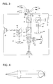
- Fig. 2 is a view conceptually showing the structure of the first optical pick-up apparatus on which the recording reproducing optical system according to the first embodiment is mounted.
- the optical pick-up apparatus 1 in Fig. 2 has a semiconductor laser 11 as the light source, hybrid refractive-diffractive coupling lens 13 (a diffraction-integrated type coupling lens), and hybrid refractive-diffractive objective lens 15 (a diffraction-integrated type objective lens).
- the semiconductor laser 11 is a GaN series blue violet laser which emits the light flux of wavelength of about 400 nm. Further, as the light source to emit the light flux of wavelength of about 400 nm, other than the above GaN series blue violet laser, a SHG blue violet laser using the secondary harmonics may also be used.
- the hybrid refractive-diffractive coupling lens 13 is a collimator lens which converts the divergent light flux from the semiconductor laser 11 into the parallel light flux parallel to the optical axis, and is the plastic lens.
- a lens by which the diverging angle of the divergent light flux from the semiconductor laser 11 is more decreased, and a lens by which the divergent light flux from the semiconductor laser 11 is converted into the convergent light flux may also be used.
- the hybrid refractive-diffractive objective lens 15 side of the hybrid refractive-diffractive coupling lens 13 almost concentric circular diffraction pattern is provided.
- the diffraction pattern of the hybrid refractive-diffractive coupling lens 13 is determined so as to satisfy the above expression (2).
- the almost concentric circular diffraction pattern may also be provided on the surface of the semiconductor laser 11 side of the hybrid refractive-diffractive coupling lens 13, or may also be provided on both of the surface of the semiconductor laser 11 side, and the surface of the hybrid refractive-diffractive objective lens 15 side.
- the diffraction pattern of the hybrid refractive-diffractive coupling lens 13 is almost concentric circular to the optical axis, however, the diffraction pattern other than this may also be used.
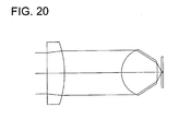
- the hybrid refractive-diffractive objective lens 15 is a lens which converges the light flux from the hybrid refractive-diffractive coupling lens 13 onto the information recording surface 16b through the protective layer 16a of the optical disk for the high density recording within the diffraction limit, and the numerical aperture on the optical disk 16 side is determined as not smaller than 0.75.
- the hybrid refractive-diffractive objective lens 15 is an aspheric surface plastic lens of one lens in one group composition, and on the surface of the hybrid refractive-diffractive coupling lens 13 side of the hybrid refractive-diffractive objective lens 15, almost concentric circular diffraction pattern is provided.
- the diffraction pattern of the hybrid refractive-diffractive objective lens 15 is determined so as to satisfy the above-described expressions (1), (4), (9), and (11). Further, in the hybrid refractive-diffractive objective lens 15, its lens thickness on the optical axis is determined so as to satisfy the above-described expression (12).
- almost concentric circular diffraction pattern may also provided on the surface of the hybrid refractive-diffractive coupling lens 13 side of the hybrid refractive-diffractive objective lens 15, or on both of the surface of the hybrid refractive-diffractive coupling lens 13 side and the surface of the optical disk 16 side.
- the diffraction pattern of the hybrid refractive-diffractive objective lens 15 is described as almost concentric circular to the optical axis, however, the diffraction pattern other than this may also be provided.
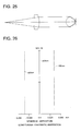
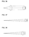
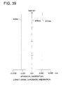
- the hybrid refractive-diffractive objective lens 15 has a flange portion 50 which has the surface vertically extended to the optical axis, and by this flange portion 50, the hybrid refractive-diffractive objective lens 15 can be accurately attached to the optical pick-up apparatus 1.
- the divergent light flux emitted from the semiconductor laser 11 is made the parallel light flux by the hybrid refractive-diffractive coupling lens 13 after it transmits the polarizing beam splitter 12, becomes the circular polarizing light through a 1/4 wavelength plate 14, and after it passes a diaphragm, not shown, it is converged on the information recording surface 16b through the protective layer 16a of the optical disk 16 by the hybrid refractive-diffractive objective lens 15, and becomes a spot.
- the hybrid refractive-diffractive objective lens 15 is focus controlled and tracking controlled by an actuator arranged in its periphery.
- the reflection light flux modulated by the information pit on the information recording surface 16b becomes a straight line polarized light after it passes again the hybrid refractive-diffractive objective lens 15, diaphragm, and 1/4 wavelength plate 14, and by the hybrid refractive-diffractive coupling lens 13, it is made the convergent light flux, reflected by the polarizing beam splitter 12, and the astigmatism is given by passing through a cylindrical lens 17 and concave lens 18, and it is converged onto the light detector 19. Then, by using the output signal of the light detector 19, the information recorded on the optical disk 16 can be read.
- the hybrid refractive-diffractive objective lens 15 is the plastic lens of one lens in one group composition, when the temperature of the hybrid refractive-diffractive objective lens 15 is risen by the radiation from the actuator 2, or rising of the environmental temperature, it changes to the direction in which the refractive index is decreased and its spherical aberration changes to the over correction direction.
- the hybrid refractive-diffractive coupling lens 13 is a plastic lens and its refracting power satisfies the above-described expression (3), when the temperature of the hybrid refractive-diffractive coupling lens 13 is risen by the radiation from the actuator 2, or rising of the environmental temperature, it changes to the direction in which the refractive index is decreased, and the light flux emitted from the hybrid refractive-diffractive coupling lens 13 becomes the convergent light flux.
- the refracting power and the diffracting power of the hybrid refractive-diffractive coupling lens 13 are determined so that they are just cancelled with the spherical aberration change to the over correction direction due to the temperature change and the spherical aberration change to the under correction direction by the lateral magnification change, of the hybrid refractive-diffractive objective lens 15, the light flux emitted from the semiconductor laser 11 is, by passing through the hybrid refractive-diffractive coupling lens 13 and the hybrid refractive-diffractive objective lens 15, even when the temperature changes, converged on the information recording surface 16b of the optical disk 16, almost without the change of the spherical aberration.
- the hybrid refractive-diffractive objective lens 15 is provided with almost concentric circular diffraction pattern satisfying the above-described expression (1) on the optical surface, to the oscillation wavelength of the semiconductor laser 11, the longitudinal chromatic aberration which is the inverse sign to the longitudinal chromatic aberration generated by the diffraction pattern of the hybrid refractive-diffractive coupling lens 13 and its absolute value is almost the same, is generated. Accordingly, the light flux emitted from the semiconductor laser 11 is converged on the information recording surface 16b of the optical disk 16 almost without the longitudinal chromatic aberration, by passing through the hybrid refractive-diffractive coupling lens 13 and the hybrid refractive-diffractive objective lens 15.
- Fig. 3 is a view generally showing +the structure of the second optical pick-up apparatus on which the recording reproducing optical system according to the second embodiment is mounted.
- the optical pick-up apparatus of the present embodiment is an optical pick-up apparatus on which the recording reproducing optical system which can conduct the recording reproducing of the information onto 3 kinds of optical disks whose thickness of the protective layers are different by one objective lens compatibly, by using the ray from 3 kinds of light sources whose wavelength are different, is mounted.
- the 3 kinds of optical disks whose thickness of the protective layers are different are the first optical disk 16 which is the high density DVD in which the protective layer is thinnest and the recording density is largest, the second optical disk 21 which is any one of each kind of DVD such as a DVD whose protective layer is 0.6 mm, DVD-ROM, DVD-RAM, DVD-R, DVD-RW, and DVD+RW, and the third optical disk 22 which is any one of each kind of CD such as a CD whose protective layer is 1.2 mm, CD-R, CD-RW, CD-video, and CD-ROM.
- the optical pick-up apparatus 1' of Fig. 3 is provided with 3 kinds of semiconductor lasers of the semiconductor laser 11 which is the first light source which generates the ray for the recording reproducing of the first optical disk 16, the semiconductor laser 31 which is the second light source which generates the ray for the recording reproducing of the second optical disk 21, and the semiconductor laser 32 which is the third light source which generates the ray for the recording reproducing of the third optical disk 22, and these semiconductor lasers are selectively light-emitted corresponding to the thickness of the protective layers of the optical disks on which the information is recorded and reproduced.
- the semiconductor laser 11 is a GaN series blue violet laser which emits the light flux of the wavelength of about 400 nm. Further, as a light source which emits the light flux of the wavelength of about 400 nm, other than the above GaN series blue violet laser, an SHG blue violet laser by using the secondary harmonics may also be used.
- the semiconductor laser 31 is a red semiconductor laser which emits the light flux of the wavelength of about 650 nm, and the semiconductor laser 32 is an infrared semiconductor laser which emits the light flux of the wavelength of about 780 nm.
- the optical pick-up apparatus 1' has the hybrid refractive-diffractive coupling lens 13 as the collimator lens to convert the divergent light flux from the semiconductor laser 11 into the parallel light flux parallel to the optical axis, and the hybrid refractive-diffractive objective lens 40.
- the hybrid refractive-diffractive objective lens 40 is a lens which converges the light flux which is emitted from the semiconductor laser 11 and passes through the hybrid refractive-diffractive coupling lens 13, onto the information recording surface 16b through the protective layer 16a of the first optical disk 16 which is the high density DVD so that it is within the diffraction limit in the first numerical aperture, further, converges the divergent light flux emitted from the semiconductor laser 31 onto the information recording surface 21b through the protective layer 21a of the second optical disk 21 which is the DVD so that it is within the diffraction limit in the second numerical aperture, and further, converges the divergent light flux emitted from the semiconductor laser 32 onto the information recording surface 22b through the protective layer 22a of the third optical disk 22 which is the CD so that it is within the diffraction limit in the third numerical aperture, and the first numerical aperture is made not lower than 0.75, the second numerical aperture is made 0.60 to 0.65, and the third numerical aperture is made 0.45 to 0.50.
- the hybrid refractive-diffractive objective lens 40 is an aspheric surface plastic lens of one lens in one group composition, and on the surface of the hybrid refractive-diffractive coupling lens 13 side of the hybrid refractive-diffractive objective lens 40, the almost concentric circular diffraction pattern is provided.
- the diffraction pattern of the hybrid refractive-diffractive objective lens 40 is determined so that the diffracted light of the short wavelength light flux forms a good wavefront to the optical disk whose protective layer is thin and the diffracted light of the long wavelength light flux forms a good wavefront to the optical disk whose protective layer is thick.
- the diffraction pattern of the hybrid refractive-diffractive objective lens 40 is determined so that the above expressions (5), (8),(9) and (11) are satisfied. Further, in the hybrid refractive-diffractive objective lens 40, its lens thickness on the optical axis is determined so that the above expression (12) is satisfied.
- the almost concentric circular diffraction pattern may also be provided on the surface of the hybrid refractive-diffractive coupling lens 13 side of the hybrid refractive-diffractive objective lens 40, or may also be provided on both of the surface of the hybrid refractive-diffractive coupling lens 13 side and the surface of the optical disk side. Further, the diffraction pattern of the hybrid refractive-diffractive objective lens 40 is made almost concentric circular to the optical axis, however, the diffraction pattern other than this may also be provided.
- the hybrid refractive-diffractive objective lens 40 has a flange portion 50 which has the surface vertically extending to the optical axis, and by this flange portion 50, the hybrid refractive-diffractive objective lens 40 can be accurately attached onto the optical pick-up apparatus 1'.
- the hybrid refractive-diffractive coupling lens 13 is a collimator lens which converts the divergent light flux from the semiconductor laser 11 into the parallel light flux which is parallel to the optical axis, and the plastic lens.
- a lens by which the divergent angle of the divergent light flux from the semiconductor laser 11 is more decreased, and a lens by which the divergent light flux from the semiconductor laser 11 is converted into the convergent light flux may also be used.
- the almost concentric circular diffraction pattern is provided on the surface of the hybrid refractive-diffractive objective lens 40 side of the hybrid refractive-diffractive coupling lens 13. Then, the diffraction pattern of the hybrid refractive-diffractive coupling lens 13 is determined so as to satisfy the above expression (6). In this connection, the almost concentric circular diffraction pattern may also be provided on the surface of the semiconductor laser 11 side of the hybrid refractive-diffractive coupling lens 13, or on both of the surface of the semiconductor laser 11 side and the surface of the hybrid refractive-diffractive objective lens 40 side. The diffraction pattern of the hybrid refractive-diffractive coupling lens 13 is made almost concentric circular to the optical axis, however, the diffraction pattern other than this may also be provided.
- the divergent light flux emitted from the semiconductor laser 11 is, after it transmits the polarizing beam splitter 12, made a parallel light flux by the hybrid refractive-diffractive coupling lens 13, and after passing through the polarizing beam splitter 41, polarizing beam splitter 42, and diaphragm, not shown, it is converged on the information recording surface 16b through the protective layer 16a of the first optical disk 16 by the hybrid refractive-diffractive objective lens 40 and becomes a spot.
- the hybrid refractive-diffractive objective lens 40 is focus-controlled and tracking-controlled by the actuator 2 arranged in its periphery.
- the reflected light flux modulated by the information pit on the information recording surface 16b is, after passing again through the hybrid refractive-diffractive objective lens 40, diaphragm, polarizing beam splitter 42, and polarizing beam splitter 41, made the convergent light flux by the hybrid refractive-diffractive coupling lens 13, reflected by the polarizing beam splitter 12, astigmatism is given by passing through the cylindrical lens 17 and concave lens 18, and it is converged to the light detector 19. Then, by using the output signal of the light detector 19, the information recorded on the first optical disk 16 can be read.
- the hybrid refractive-diffractive objective lens 40 is a plastic lens of one lens in one group composition, when the temperature of the hybrid refractive-diffractive objective lens 15 is risen by the radiation from the actuator 2, or rising of the environmental temperature, it changes to the direction in which the refractive index is decreased and its spherical aberration changes to the over correction direction.
- the hybrid refractive-diffractive coupling lens 13 is a plastic lens and its refracting power satisfies the above-described expression (7), when the temperature of the hybrid refractive-diffractive coupling lens 13 is risen by the radiation from the actuator 2, or rising of the environmental temperature, it changes to the direction in which the refractive index is decreased, and the light flux emitted from the hybrid refractive-diffractive coupling lens 13 becomes the convergent light flux.
- the refracting power and the diffracting power of the hybrid refractive-diffractive coupling lens 13 are determined so that they are just cancelled with the spherical aberration change to the over correction direction due to the temperature change and the spherical aberration change to the under correction direction by the lateral magnification change, of the hybrid refractive-diffractive objective lens 15, the light flux emitted from the semiconductor laser 11 is, by passing through the hybrid refractive-diffractive coupling lens 13 and the hybrid refractive-diffractive objective lens 40, even when the temperature changes, converged on the information recording surface 16b of the optical disk 16, almost without the change of the spherical aberration.
- the hybrid refractive-diffractive objective lens 40 is provided with almost concentric circular diffraction pattern satisfying the above-described expression (5) on the optical surface, to the oscillation wavelength of the semiconductor laser 11, the longitudinal chromatic aberration which is the inverse sign to the longitudinal chromatic aberration generated by the diffraction pattern of the hybrid refractive-diffractive coupling lens 13 and its absolute value is almost the same, is generated. Accordingly, the light flux emitted from the semiconductor laser 11 is converged on the information recording surface 16b of the optical disk 16 almost without the longitudinal chromatic aberration, by passing through the hybrid refractive-diffractive coupling lens 13 and the hybrid refractive-diffractive objective lens 40.
- the divergent light flux emitted from the semiconductor laser 31 is, after it transmits the polarizing beam splitter 12', reflected by the polarizing beam splitter 41, and after passing through the polarizing splitter 42 and diaphragm, not shown, it is converged on the information recording surface 21b, by the hybrid refractive-diffractive objective lens 40, through the protective layer 21a of the second optical disk 21, and becomes a spot.
- the hybrid refractive-diffractive objective lens 40 is focus-controlled and tracking-controlled by the actuator 2 arranged in its periphery.
- the reflected light flux modulated by the information pit on the information recording surface 21b is, after passing again through the hybrid refractive-diffractive objective lens 40, diaphragm, polarizing beam splitter 42, and after reflected by the polarizing beam splitter 41, reflected by the polarizing beam splitter 12', the astigmatism is given by passing through the cylindrical lens 17' and concave lens 18', and it is converged to the light detector 19'. Then, by using the output signal of the light detector 19', the information recorded on the second optical disk 21 can be read.
- the divergent light flux emitted from the semiconductor laser 32 is, after it transmits the polarizing beam splitter 12", reflected by the polarizing beam splitter 42, and after passing through the diaphragm, not shown, it is converged on the information recording surface 22b, by the hybrid refractive-diffractive objective lens 40, through the protective layer 22a of the third optical disk 22, and becomes a spot.
- the hybrid refractive-diffractive objective lens 40 is focus-controlled and tracking-controlled by the actuator 2 arranged in its periphery.
- the reflected light flux modulated by the information pit on the information recording surface 22b is, after passing again through the hybrid refractive-diffractive objective lens 40 and diaphragm, and after reflected by the polarizing beam splitter 42 and the polarizing beam splitter 12", the astigmatism is given by passing through the cylindrical lens 17" and concave lens 18", and it is converged to the light detector 19". Then, by using the output signal of the light detector 19", the information recorded on the third optical disk 22 can be read.
- the optical pick-up apparatus 1' is provided with the 1/4 wavelength plates, not shown, in respective optical paths between the semiconductor laser 11 and the hybrid refractive-diffractive objective lens 40, between the semiconductor laser 31 and the hybrid refractive-diffractive objective lens 40, and between the semiconductor laser 32 and the hybrid refractive-diffractive objective lens 40.
- the optical pick-up apparatus 1' as shown in Fig. 3 is, for example, can be mounted on the recording apparatus and/or reproducing apparatus of the voice and/or image of devices such as a player or drive, compatible to the optical information recording media such as, each kind of CD such as the CD, CD-R, CD-RW, CD-Video, CD-ROM, each kind of DVD such as DVD, DVD-ROM, DVD-RAM, DVD-R, DVD-RW, DVD+RW, and MD, or an AV device including them, a personal computer, and other information terminal equipment.
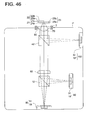
- Fig. 46 is a view generally showing the structure of the third optical pickup apparatus in which the recording reproducing optical system according to the third embodiment is mounted.
- An optical pickup apparatus of the present embodiment is an optical pickup apparatus in which a recording reproducing optical system by which the recording reproducing of the information can be compatibly conducted by an objective lens, is mounted, by using the light from 3 kinds of light sources whose wavelength is different from each other, on 3 kinds of optical disks whose recording density is different from each other.
- the 3 kinds of optical disks comprise the first optical disk 23 as the high density DVD whose recording density is the largest and the protective layer is 0.6 mm in thickness uses the shortest wavelength light flux of wavelength of about 400 nm for recording reproducing of the information, and the second optical disk 21 which is any one of each kind of DVDs such as a DVD, DVD-ROM, DVD RAM, DVD-R, DVD-RW, and DVD+RW, whose protective layer is 0.6 mm in thickness and the third optical disk 22 as each kind of CDs such as CD, CD-R, CD-RW, CD-video, CD-ROM, whose protective layer is 1.2 mm in thickness.
- the optical pickup apparatus 1" is provided with: a module 80 for the first optical disk which is integrated with a semiconductor laser 11 as the first light source which generates a light flux for recording reproducing of the first optical disk 23 and a photo-detector 19; a module 90 for the second optical disk which is integrated with a semiconductor laser 31 as the second light source which generates a light flux for the recording reproducing of the second optical disk 21 and a photo-detector 19'; and a module 100 for the third optical disk which is integrated with a semiconductor laser 32 as the third light source which generates a light flux for the recording reproducing of the third optical disk 22 and a photo-detector 19", and these semiconductor lasers whose wavelengths are different, are selected so as to emit a light flux in accordance with the recording density of the optical disk which records and reproduces the information.
- the semiconductor laser 11 is a GaN series blue-violet laser which emits the light flux of the wavelength of about 400 nm. Further, as the light source which emits the light flux of the wavelength of about 400 nm, other than the GaN series blue violet laser, an SHG blue violet laser using the second harmonic generation may also be used.
- the semiconductor laser 31 is a red semiconductor laser which emits the light flux of the wavelength of about 650 nm, and the semiconductor laser 32 is an infrared semiconductor laser which emits the light flux of the wavelength of about 780 nm.
- the optical pickup apparatus 1" has a hybrid refractive-diffractive coupling lens 60 as the collimator lens which converts the divergent light flux from the semiconductor laser 11 and semiconductor laser 31 into the parallel light flux which is parallel to the optical axis, and this hybrid refractive-diffractive coupling lens 60 is arranged in the optical path through which both of the light fluxes from the semiconductor laser 11 and semiconductor laser 31 pass.
- a hybrid refractive-diffractive objective lens 70 is a lens which converges the light flux which is emitted from the semiconductor laser 11 and though the hybrid refractive-diffractive coupling lens 60, on the information recording surface 23b through the protective layer 23a of the first optical disk 23, so as to be in the diffraction limit in the first numerical aperture, and the light flux which is emitted from the semiconductor laser 31 and though the hybrid refractive-diffractive coupling lens 60, on the information recording surface 21b through the protective layer 21a of the second optical disk 21 which is the DVD, so as to be in the diffraction limit in the second numerical aperture, and the divergent light flux which is emitted from the semiconductor laser 32, on the information recording surface 22b through the protective layer 22a of the third optical disk 22 which is the CD, so as to be in the diffraction limit in the third numerical aperture, and whose first numerical aperture is almost 0.65, the second numerical aperture is 0.60 to 0.65, and the third numerical aperture is 0.45 to 0.50.
- the hybrid refractive-diffractive objective lens 70 is 1 group 1 aspheric plastic lens, and on the surface of the hybrid refractive-diffractive coupling lens 60 side of the hybrid refractive-diffractive objective lens 70, almost concentric ring-shaped diffractive patterns are provided.
- the diffraction pattern of the hybrid refractive-diffractive objective lens 70 satisfies the formula (PD1 > 0, where PD1 is a diffractive power (mm -1 ) as a diffractive lens), and because it has the wavelength characteristic by which, to the diffraction order (n1 is defined) of the diffracted ray having the maximum diffraction efficiency among the diffracted rays generated when the light flux emitted from the semiconductor laser 11 is incident, the diffraction orders (respectively n2, n3 are defined) of the diffracted ray having the maximum diffraction efficiency among the diffracted rays generated when the light fluxes emitted from the semiconductor laser 31 and the semiconductor laser 32 are incident, are determined so as to be lower orders, and the diffracted ray of the light flux emitted from the semiconductor laser 11 forms a good wave front on the information recording surface 23a of the first optical disk 23 whose recording density is highest, the diffracted ray of the light flux emitted from
- almost concentric ring-shaped diffractive pattern may also be provided on the surface of the hybrid refractive-diffractive coupling lens 60 side of the hybrid refractive-diffractive objective lens 70, or it may also be provided on both of the surface of the hybrid refractive-diffractive coupling lens 60 side and the surface of the optical disk side.
- the diffraction pattern of the hybrid refractive-diffractive objective lens 70 is defined as almost concentric rings to the optical axis, however, the diffraction pattern other than this, may also be provided.
- the hybrid refractive-diffractive objective lens 70 has a flange portion 50 having a surface vertically extending to the optical axis, and by this flange portion 50, the hybrid refractive-diffractive objective lens 70 can be accurately attached to the optical pickup apparatus 1".
- the hybrid refractive-diffractive coupling lens 60 is a collimator lens which converts the divergent light fluxes from the semiconductor laser 11 and semiconductor laser 31 into the parallel light fluxes parallel to the optical axis, and is a plastic lens.
- a lens by which the divergent angle of the divergent light flux from the semiconductor laser 11 and the semiconductor laser 31 is more reduced, or a lens by which the divergent light flux from the semiconductor laser 11 and the semiconductor laser 31 is converted into a convergent light flux may also be used.
- a lens by which the divergent light flux from the semiconductor laser 11 is converted into the parallel light flux, and the divergent angle of the divergent light flux from the semiconductor 31 is more reduced may also be allowable, or a lens by which the divergent light flux from the semiconductor laser 11 is converted into the parallel light flux, and the divergent light flux from the semiconductor 31 is converted into the convergent light flux, may also be allowed.
- a lens by which the divergent light flux from the semiconductor laser 31 is converted into the parallel light flux, and the divergent angle of the divergent light flux from the semiconductor 11 is more reduced may also be allowable, or a lens by which the divergent light flux from the semiconductor laser 31 is converted into the parallel light flux, and the divergent light flux from the semiconductor 11 is converted into the convergent light flux, may also be allowed.
- a lens by which the divergent angle of the divergent light flux from one hand semiconductor laser is more reduced, and the divergent light flux from the other semiconductor laser is converted into the convergent light flux may also be allowable.
- the diffraction pattern of the hybrid refractive-diffractive coupling lens 60 is designed so as to satisfy the formula (PD2 ⁇ 0, PD2 is a diffractive power (mm -1 ) as a diffractive lens), and because, to the diffraction order (n1' is defined) of the diffracted ray having the maximum diffraction efficiency in the diffracted ray generated when the light flux emitted from the semiconductor laser 11 is incident, the diffraction order (n2' is defined) of the diffracted ray having the maximum diffraction efficiency in the diffracted ray generated when the light flux emitted from the semiconductor laser 31 is incident, is determined so as to be lower order, the high diffraction efficiency can be maintained to the wavelength ranges of respective semiconductor lasers, and the divergent light fluxes
- any one of (n1', n2') (2, 1), (3, 2), (4, 2), (5, 3), (6, 4), (7, 4), (8, 5), (9, 6), (10, 6), may be selected.
- the almost concentric ring-shaped diffractive pattern may also be provided on the surface of the semiconductor laser 11 side of the hybrid refractive-diffractive coupling lens 60, or may also be provided on both of the surface of the semiconductor laser 11 side and the surface of the hybrid refractive-diffractive objective lens 70 side.
- the diffraction pattern of the hybrid refractive-diffractive coupling lens 60 is defined as almost concentric rings to the optical axis, however, the diffraction pattern other than this may also be provided.
- the hybrid refractive-diffractive objective lens 70 is focus-controlled and tracking-controlled by an actuator 2 arranged in its periphery.
- the reflected light flux modulated by the information pit on the information recording surface 23b passes again through the hybrid refractive-diffractive objective lens 70, stop, polarizing beam splitter 42, it is made a convergent light flux by the hybrid refractive-diffractive coupling lens 60, and converged on the light receiving surface of the photo-detector 19. Then, by using the output signal of the photo-detector 19, the information recorded on the first optical disk 23 can be read.
- the hybrid refractive-diffractive objective lens 70 is focus-controlled and tracking-controlled by the actuator 2 arranged in its periphery.
- the reflected light flux modulated by the information pit on the information recording surface 21b passes again through the hybrid refractive-diffractive objective lens 70, stop, polarizing beam splitter 42, it is made a convergent light flux by the hybrid refractive-diffractive coupling lens 60, it is reflected by the polarizing beam splitter 12, and converged on the light receiving surface of the photo-detector 19'. Then, by using the output signal of the photo-detector 19', the information recorded on the second optical disk 21 can be read.
- the hybrid refractive-diffractive objective lens 70 is a plastic lens structure in one element in one group, by the heat radiation from the actuator 2 or the rise of the environmental temperature, when the temperature of the hybrid refractive-diffractive objective lens 70 is risen, it changes to the direction in which the refractive index is reduced, and its spherical aberration changes to the over-corrected direction.
- the hybrid refractive-diffractive coupling lens 60 is a plastic lens, and because its refractive power satisfies the formula (PR2 > 0, where PR2 is a refractive power (mm -1 ) as a refractive lens), when the temperature of the hybrid refractive-diffractive coupling lens 60 is risen by the heat radiation from the actuator 2 or the environmental temperature rise, it changes to the direction in which the refractive index is reduced, and the light flux emitted from the hybrid refractive-diffractive coupling lens 60 becomes the convergent light flux.
- the refractive power and the diffraction power of the hybrid refractive-diffractive coupling lens 60 are determined in such a manner that the spherical aberration change to the over-corrected direction by the temperature change and the spherical aberration change to the under-corrected direction by the lateral magnification change of the hybrid refractive-diffractive objective lens 70 are just cancelled, when the light flux emitted from the semiconductor laser 11 and the semiconductor laser 31 passes through the hybrid refractive-diffractive coupling lens 60 and hybrid refractive-diffractive objective lens 70, even when the temperature changes, the light is converged on respective information recording surfaces of the first optical disk 23 and the second optical disk 21 almost without the spherical aberration.
- the hybrid refractive-diffractive objective lens 70 is provided with an almost concentric ring-shaped diffractive pattern satisfying the above formula (PD1 > 0) on the optical surface, to the oscillation wavelength of the semiconductor laser 11 and semiconductor 31, the axial chromatic aberration which is an inverse sign and its absolute value almost coincides with the axial chromatic aberration generated in the diffraction pattern of the hybrid refractive-diffractive coupling lens 60, is generated.
- the light fluxes emitted from the semiconductor laser 11 and the semiconductor laser 31 are converged on respective information recording surfaces of the first optical disk 23 and the second optical disk 21 almost without axial chromatic aberration when they pass through the hybrid refractive-diffractive coupling lens 60 and the hybrid refractive-diffractive objective lens 70.
- the hybrid refractive-diffractive objective lens 70 is focus-controlled and tracking-controlled by the actuator 2 arranged in its periphery.
- the reflected light flux modulated by the information pit on the information recording surface 22b passes again through the hybrid refractive-diffractive objective lens 70 and a stop, it is reflected by the polarizing beam splitter 42, and converged on the light receiving surface of the optical detector 19". Then, by using the output signal of the optical detector 19", the information recorded on the third optical disk 22 can be read.
- the optical pickup apparatus 1" as shown in Fig. 46 can be mounted in a player or drive, or an AV device in which they are assembled, personal computer, a recording and/or reproducing apparatus of an audio and/or image of the other information terminal equipment, for example, which is compatible with the optical information recording medium such as each kind of CDs, such as CD, CD-R, CD-RW, CD-video, CD-ROM, each kind of DVDs such as DVD, DVD-ROM, DVD-RAM, DVD-R, DVD-RW, DVD+RW, and an MD.
- CDs such as CD, CD-R, CD-RW, CD-video, CD-ROM
- each kind of DVDs such as DVD, DVD-ROM, DVD-RAM, DVD-R, DVD-RW, DVD+RW, and an MD.
- the high density DVD for which the blue violet semiconductor laser is used as the light source for the recording reproducing is defined as an optical disk in which the thickness of the protective layer is 0.6 mm, and the numerical aperture of the objective lens is almost 0.65, however, even when it is an optical disk (for example, the optical disk of the Blue-ray disk standard disclosed on Feb. 2002) as the high density DVD in which the thickness of the protective layer is 0.1 mm, and the numerical aperture of the objective lens is almost 0.85, it is needless to say that the technology according to the present invention can be applied.
- the present invention will be more specifically described below by the Examples 1 to 8, however, the present invention is not limited to these examples.
- the optical axis direction is X axis
- the height in the direction vertical to the optical axis is h
- the radius of curvature of the refractive surface is r
- the aspheric surface in each lens of the present example is shown by the following Arith. 1.
- ⁇ is a conical coefficient
- a 2i is an asheric surface coefficient.
- the ring-shaped zone-like diffractive structure provided on the objective lens of the present example can be expressed by the above expression (A) when the optical path difference function is made ⁇ b
- the ring-shaped zone-like diffractive structure provided on each aberration correcting optical element can be expressed by the above expression (B) when the optical path difference function is made ⁇ b .
- the Example 1 is a recording reproducing optical system appropriate for the optical pick-up apparatus in Fig. 2.
- the present example is an optical system in which the hybrid refractive-diffractive collimator lens and the hybrid refractive-diffractive objective lens are combined, and as the hybrid refractive-diffractive collimator lens, the plastic lens of one lens in one group composition of the focal distance 8 mm, NA 0.28 is used, and as the hybrid refractive-diffractive objective lens, the plastic lens of one lens in one group composition of the focal distance 2.2 mm, NA 0.85 is used.
- the surface of the optical disk side of the hybrid refractive-diffractive collimator lens is the diffractive surface having the negative diffracting power
- the surface of the semiconductor laser side of the hybrid refractive-diffractive objective lens is the diffractive surface having the positive diffracting power.
- Table 1 the data relating to the recording reproducing optical system of the Example 1 will be shown.
- Fig. 4 the optical path view of the recording reproducing optical system of Example 1 will be shown.
- Fig. 5 is a graph showing the spherical aberration and longitudinal chromatic aberration at the wavelength 405 ⁇ 5 nm of the hybrid refractive-diffractive collimator lens of the present example
- Fig. 6 is a graph showing the spherical aberration and longitudinal chromatic aberration at the wavelength 405 ⁇ 5 nm of the hybrid refractive-diffractive objective lens of the present example
- Fig. 5 is a graph showing the spherical aberration and longitudinal chromatic aberration at the wavelength 405 ⁇ 5 nm of the hybrid refractive-diffractive objective lens of the present example
- Fig. 6 is a graph showing the spherical aberration and longitudinal chromatic aberration at the wavelength 405 ⁇ 5 nm of the hybrid refractive-diffractive objective lens of the present example
- FIG. 7 is a graph showing the spherical aberration and longitudinal chromatic aberration at the wavelength 405 ⁇ 5 nm of the recording reproducing optical system in which the hybrid refractive-diffractive collimator lens and the hybrid refractive-diffractive objective lens are combined.
- Fig. 8 the temperature characteristic of the recording reproducing optical system of Example 1 is shown.
- the operable temperature range is -10 to 40 °C which is very narrow, when it is combined with the hybrid refractive-diffractive collimator lens, the good light converging characteristic can be maintained in the temperature range of -20 to +85 °C.
- the refractive index change (the changing rate is -1.1 x 10 -4 / °C) of the plastic lens to the temperature change and the wavelength change of the blue violet semiconductor laser (its changing rate is + 0.05 nm/°C) are considered, and because the influence of the shape change of the plastic lens on the change of the wave front aberration is very small comparing to the refractive index change, the shape change of the plastic lens is not considered.
- the condition when the wave front aberration at the above-described temperature change is calculated, is the same also in the examples 2 to 7 which will be described later.
- Fig. 9 the wavelength characteristic of the recording reproducing optical system of Example 1 is shown. It can be seen that, although, in the blue violet semiconductor laser, the wavelength is changed by 1 to 2 nm by the mode hopping, even the objective lens which, in a single body, by the wavelength change of 2 nm, largely exceeds the Marechal's criterion of 0.07 ⁇ rms, when it is combined with the hybrid refractive-diffractive collimator lens, the good light converging characteristic can be maintained even when the wavelength is changed by 2 nm.
- the wave front aberration in Fig. 9 includes the de-focus component by the movement of the best image point position.
- the condition in the case where the wave front aberration is calculated when the wavelength change by the above-described mode hopping occurs is the same also in examples 2 to 7 which will be described later.
- Example 2 is an optical system in which a diffraction integrated beam expander as the aberration correcting optical element and the hybrid refractive-diffractive objective lens are combined, and as the diffraction integrated beam expander, the plastic lens of two lenses in two groups composition of an entrance pupil diameter 3.16 mm, exit pupil diameter 4.50 mm, and angle magnification 1.47, is used, and as the hybrid refractive-diffractive objective lens, the plastic lens of one lens in one group composition of the focal distance 2.2 mm, and NA 0.85 is used.
- both surfaces of the positive lens of the diffraction integrated beam expander are the diffractive surfaces having the negative diffracting power
- both surfaces of the hybrid refractive-diffractive objective lens are the diffractive surfaces having the positive diffracting power.
- Table 2 the data relating to the recording reproducing optical system of Example 2 is shown.
- surface No. r (mm) d (mm) N ⁇ ⁇ d Note 0 ⁇ 1 -14.6582 1.0000 1.52491 56.5 2 6.9680 2.7535 3 21.5525 1.8000 1.52491 56.5 4 -5.0607 10.0000 5 1.7316 3.2700 1.52491 56.5 6 -1.8541 0.4254 7 ⁇ 0.1000 1.61949 30.0 8 ⁇
- Fig. 10 the optical path view of the recording reproducing optical system of Example 2 is shown.
- Fig. 11 is a graph showing the spherical aberration and longitudinal chromatic aberration in wavelength 405 ⁇ 5 nm of the hybrid refractive-diffractive objective lens of the present example
- Fig. 12 is a graph showing the spherical aberration and longitudinal chromatic aberration in wavelength 405 ⁇ 5 nm of the recording reproducing optical system in which the diffraction integrated beam expander and the hybrid refractive-diffractive objective lens are combined.
- Fig. 13 the temperature characteristic of the recording reproducing optical system of the present example is shown. As can be seen from 13, when the high NA plastic objective lens and diffraction integrated beam expander are combined, the good light converging characteristic can be maintained in the temperature range of -20 to + 85 °C.
- Fig. 14 the wavelength characteristic of the recording reproducing optical system of the present example is shown. As can be seen from Fig. 14, when the high NA plastic objective lens and diffraction integrated beam expander are combined, even when the wavelength change of 2 nm occurs, the good light converging characteristic can be maintained.
- Example 3 is an optical system in which the diffraction integrated beam expander as the aberration correcting optical system and the hybrid refractive-diffractive objective lens are combined, and as the diffraction integrated beam expander, the beam expander of two lenses in two groups composition of the entrance pupil diameter 2.47 mm, exit pupil diameter 4.50 mm, and angle magnification 1.84, is used, and as the hybrid refractive-diffractive objective lens, the plastic lens of one lens in one group composition of the focal distance 2.2 mm and NA 0.85, is used.
- the positive lens of the diffraction integrated beam expander is the plastic lens and the negative lens is a glass lens (made by HOYA co, FD110) whose Abbe's number is smaller than the positive lens.
- the surface of the optical disk side of the positive lens of the diffraction integrated beam expander is the diffractive surface having the negative diffracting power
- the surface of the semiconductor laser side of the hybrid refractive-diffractive objective lens is the diffractive surface having the positive diffracting power.
- Table 3 the data relating to the recording reproducing optical system of Example 3 is shown.
- surface No. r (mm) d (mm) N ⁇ ⁇ d Note 0 ⁇ 1 -4.9735 1.0000 1.84203 25.7 2 ⁇ 3.2579 3 ⁇ 1.8000 1.52469 56.5 4 -4.3064 10.0000 5 1.5943 3.2000 1.52491 56.5 6 -1.4072 0.4059 7 ⁇ 0.1000 1.61949 30.0 8 ⁇
- Fig. 15 the optical path view of the recording reproducing optical system of Example 3 is shown.
- Fig. 16 is a graph showing the spherical aberration and longitudinal chromatic aberration in wavelength 405 ⁇ 5 nm of the hybrid refractive-diffractive objective lens of the present example
- Fig. 17 is a graph showing the spherical aberration and longitudinal chromatic aberration in wavelength 405 ⁇ 5 nm of the recording reproducing optical system in which the diffraction integrated beam expander and the hybrid refractive-diffractive objective lens are combined.
- Fig. 18 the temperature characteristic of the recording reproducing optical system of the present example is shown. As can be seen from Fig. 18, when the high NA plastic objective lens and diffraction integrated beam expander are combined, the good light converging characteristic can be maintained in the temperature range of -20 to + 85 °C.
- Fig. 19 the wavelength characteristic of the recording reproducing optical system of the present example is shown. As can be seen from Fig. 19, when the high NA plastic objective lens and diffraction integrated beam expander are combined, even when the wavelength change of 2 nm occurs, the good light converging characteristic can be maintained.
- Example 4 is an optical system in which the diffraction integrated plastic lens as the aberration correcting optical system and the hybrid refractive-diffractive objective lens are combined, and as the aberration correcting optical element, the plastic lens of one lens in one group composition of the entrance pupil diameter 4.50 mm, exit pupil diameter 4.70 mm, and numerical aperture 0, is used, and as the hybrid refractive-diffractive objective lens, the plastic lens of one lens in one group composition of the focal distance 2.2 mm and NA 0.85, is used.
- the flat surface of the light source side of the aberration correcting optical element is the diffractive surface having the negative diffracting power
- the surface of the semiconductor laser side of the hybrid refractive-diffractive objective lens is the diffractive surface having the positive diffracting power.
- Table 4 the data relating to the recording reproducing optical system of Example 4 is shown. surface No. r (mm) d (mm) N ⁇ ⁇ d Note 0 ⁇ 1 ⁇ 1.5000 1.52491 56.5 2 -8.0797 5.0000 3 1.6893 3.0500 1.52491 56.5 4 -1.7971 0.4188 5 ⁇ 0.1000 1.61949 30.0 6 ⁇
- Fig. 20 the optical path view of the recording reproducing optical system of Example 4 is shown.
- Fig. 21 is a graph showing the spherical aberration and longitudinal chromatic aberration in wavelength 405 ⁇ 5 nm of the hybrid refractive-diffractive objective lens of the present example
- Fig. 22 is a graph showing the spherical aberration and longitudinal chromatic aberration in wavelength 405 ⁇ 5 nm of the recording reproducing optical system in which the aberration correcting optical element and the hybrid refractive-diffractive objective lens are combined.
- Fig. 23 the temperature characteristic of the recording reproducing optical system of the present example is shown. As can be seen from Fig. 23, when the high NA plastic objective lens and aberration correcting optical element are combined, the good light converging characteristic can be maintained in the temperature range of -2.0 to + 85 °C.
- Fig. 24 the wavelength characteristic of the recording reproducing optical system of the present example is shown. As can be seen from Fig. 24, when the high NA plastic objective lens and aberration correcting optical element are combined, even when the wavelength change of 2 nm occurs, the good light converging characteristic can be maintained.
- Example 5 is an optical system in which the hybrid refractive-diffractive coupling lens as the aberration correcting optical element and the hybrid refractive-diffractive objective lens are combined, and as the aberration correction coupling lens, the plastic lens of one lens in one group composition of the focal distance 11.02 mm, light source side NA 0.19, and lateral magnification -0.074, is used, and as the hybrid refractive-diffractive objective lens, the plastic lens of one lens in one group composition of the focal distance 2.2 mm, optical disk side NA 0.85, and lateral magnification 0.015, is used.
- the surface of the optical disk side of the hybrid refractive-diffractive coupling lens is the diffractive surface having the negative diffracting power
- both surfaces of the hybrid refractive-diffractive objective lens are the diffractive surfaces having the positive diffracting power.
- Table 5 the data relating to the recording reproducing optical system of Example 5 is shown. surface No. r (mm) d (mm) N ⁇ ⁇ d Note 0 10.7681 1 27.4919 2.0000 1.52469 56.5 2 -6.3582 10.0000 3 1.6162 3.2200 1.52491 56.5 4 -1.7141 0.4207 5 ⁇ 0.1000 1.61949 30.0 6 ⁇
- Fig. 25 the optical path view of the recording reproducing optical system of Example 5 is shown.
- Fig. 26 is a graph showing the spherical aberration and longitudinal chromatic aberration in wavelength 405 ⁇ 5 nm of the hybrid refractive-diffractive coupling lens of the present example
- Fig. 27 is a graph showing the spherical aberration and longitudinal chromatic aberration in wavelength 405 ⁇ 5 nm of the hybrid refractive-diffractive objective lens of the present example
- Fig. 26 is a graph showing the spherical aberration and longitudinal chromatic aberration in wavelength 405 ⁇ 5 nm of the hybrid refractive-diffractive objective lens of the present example
- Fig. 27 is a graph showing the spherical aberration and longitudinal chromatic aberration in wavelength 405 ⁇ 5 nm of the hybrid refractive-diffractive objective lens of the present example
- Fig. 26 it can be seen that, in the hybrid refractive-diffractive coupling lens of the present example, when the wavelength of the incident ray is changed to the long wavelength side, the focal point position is moved to the over side, and when the wavelength of the incident ray is changed to the short wavelength side, the focal point position is moved to the under side. Further, from Fig. 27, it can be seen that, in the hybrid refractive-diffractive objective lens of the present example, when the wavelength of the incident ray is changed to the long wavelength side, the focal point position is moved to the under side, and when the wavelength of the incident ray is changed to the short wavelength side, the focal point position is moved to the over side. Further, from Fig. 28, it can be seen that, in the recording reproducing optical system in which the hybrid refractive-diffractive coupling lens and the hybrid refractive-diffractive objective lens are combined, the focal point position is hardly changed in spite of the wavelength.
- Fig. 29 the temperature characteristic of the recording reproducing optical system of the present example is shown. As can be seen from Fig. 29, when the high NA plastic objective lens and aberration correcting optical element are combined, the good light converging characteristic can be maintained in the temperature range of -20 to + 85 °C.
- Fig. 30 the wavelength characteristic of the recording reproducing optical system of the present example is shown. As can be seen from Fig. 30, when the high NA plastic objective lens and hybrid refractive-diffractive coupling lens are combined, even when the wavelength change of 2 nm occurs, the good light converging characteristic can be maintained.
- Example 6 is an optical system in which the hybrid refractive-diffractive collimator lens as the aberration correcting optical element and junction type doublet lens as the chromatic aberration correcting optical element, and the hybrid refractive-diffractive objective lens are combined, and as the hybrid refractive-diffractive collimator lens, the plastic lens of one lens in one group composition of the focal distance 7 mm, and NA 0.375, is used, and as the hybrid refractive-diffractive objective lens, the plastic lens of one lens in one group composition of the focal distance 2.2 mm and optical disk side NA 0.85, is used.
- the negative lens made by HOYA co, FD110
- the positive lens made by HOYA co, TAF5
- the refracting power is zero.
- the surface of the optical disk side of the hybrid refractive-diffractive collimator lens is the diffractive surface having the negative diffracting power
- the surface of the light source side of the hybrid refractive-diffractive objective lens is the diffractive surfaces having the positive diffracting power.
- Fig. 31 the optical path view of the recording reproducing optical system of Example 6 is shown.
- Fig. 32 is a graph showing the spherical aberration and longitudinal chromatic aberration in wavelength 405 ⁇ 5 nm of the optical system in which the hybrid refractive-diffractive collimator lens of the present example, and hybrid refractive-diffractive objective lens are combined
- Fig. 33 is a graph showing the spherical aberration and longitudinal chromatic aberration in wavelength 405 ⁇ 5 nm of the recording reproducing optical system in which the hybrid refractive-diffractive collimator lens, junction type doublet lens and hybrid refractive-diffractive objective lens are combined.
- Fig. 32 it can be seen that, in the optical system in which the hybrid refractive-diffractive collimator lens of the present example, and the hybrid refractive-diffractive objective lens are combined, when the wavelength of the incident ray is changed to the long wavelength side, the focal point position is moved to the over side, and when the wavelength of the incident ray is changed to the short wavelength side, the focal point position is moved to the under side.
- Fig. 33 it can be seen that, in the recording reproducing optical system in which the hybrid refractive-diffractive collimator lens and the junction type doublet lens and the hybrid refractive-diffractive objective lens are combined, the focal point position is hardly changed in spite of the wavelength.
- Fig. 34 the temperature characteristic of the recording reproducing optical system of the present example is shown. As can be seen from Fig. 34, when the high NA plastic objective lens and aberration correcting optical element are combined, the good light converging characteristic can be maintained in the temperature range of -20 to + 85 °C.
- Fig. 35 the wavelength characteristic of the recording reproducing optical system of the present example is shown.
- the "recording reproducing optical system” shows the optical system in which the hybrid refractive-diffractive collimator lens, junction type doublet lens and hybrid refractive-diffractive objective lens are combined
- "COL +OBJ” shows the optical system in which the hybrid refractive-diffractive collimator lens and the hybrid refractive-diffractive objective lens are combined.
- Example 7 is the recording reproducing optical system appropriate for the optical pick-up apparatus of Fig. 3.
- the present example is the recording reproducing optical system in which the recording reproducing of the information can be conducted compatibly by the one objective lens to the high density DVD, DVD and CD, and the hybrid refractive-diffractive collimator lens as the aberration correcting optical element, as the aberration correcting optical element, is arranged in the optical path between the blue violet semiconductor laser for the high density DVD and the hybrid refractive-diffractive objective lens.
- the divergent light flux emitted from the semiconductor laser for DVD and the semiconductor laser for CD is made to be incident on the hybrid refractive-diffractive objective lens, and made converge on respective information recording surfaces of DVD and CD.
- hybrid refractive-diffractive collimator lens a plastic lens of one lens in one group composition of the focal distance 7 mm, NA 0.321 is used, and as hybrid refractive-diffractive objective lens, the plastic lens of one lens in one group composition of the focal distance 2.0 mm is used. Further, NA of the hybrid refractive-diffractive objective lens is 0.85 at the time of recording reproducing onto the high density DVD, 0.65 at the time of recording reproducing onto DVD, and 0.50 at the time of recording reproducing onto CD.
- the surface of the optical disk side of the hybrid refractive-diffractive collimator lens is the diffractive surface having the negative diffracting power
- the surface of the semiconductor laser side of the hybrid refractive-diffractive objective lens is the diffractive surface having the positive diffracting power
- Table 7 the data relating to the recording reproducing optical system of Example 7 is shown, and in Figs. 36 to 38, the optical path view of the recording reproducing optical system of the present example is shown.
- the diffractive surface coefficient of the surface of the light source side of the objective lens is determined so that the second order diffracted ray is generated, when the ray from the blue violet semiconductor laser is incident.
- the primary order diffracted ray is generated.
- the reference wavelength (also called the production wavelength of the diffractive structure) of the diffractive surface coefficient of the surface of the light source side of the objective lens is set to 380 nm, the high diffraction efficiency can be obtained in respective wavelength regions of the ray from the blue violet semiconductor laser, the ray from the red semiconductor laser, and the ray from the infrared semiconductor laser.
- Fig. 36 is an optical path view when the recording reproducing of the information is conducted onto the high density DVD
- Fig. 37 is an optical path view when the recording reproducing of the information is conducted onto DVD
- Fig. 38 is an optical path view when the recording reproducing of the information is conducted onto CD.
- Fig. 39 is a graph showing the spherical aberration and longitudinal chromatic aberration in wavelength 405 ⁇ 5 nm of the hybrid refractive-diffractive collimator lens of the present example
- Fig. 40 is a graph showing the spherical aberration and longitudinal chromatic aberration in wavelength 405 ⁇ 5 nm of the hybrid refractive-diffractive objective lens of the present example
- Fig. 39 is a graph showing the spherical aberration and longitudinal chromatic aberration in wavelength 405 ⁇ 5 nm of the hybrid refractive-diffractive collimator lens of the present example
- Fig. 40 is a graph showing the spherical aberration and
- Fig. 41 is a graph showing the spherical aberration in wavelength 650 nm of the hybrid refractive-diffractive objective lens of the present example
- Fig. 42 is a graph showing the spherical aberration in wavelength 780 nm of the hybrid refractive-diffractive objective lens of the present example
- Fig. 43 is a graph showing the spherical aberration and longitudinal chromatic aberration in wavelength 405 ⁇ 5 nm of the recording reproducing optical system in which the aberration correcting optical element and hybrid refractive-diffractive objective lens are combined.
- Fig. 40 it can be seen that, in the hybrid refractive-diffractive objective lens of the present example, when the wavelength of the ray from the blue violet semiconductor laser is changed to the long wavelength side, the focal point position is moved to the under side, and when the wavelength of the ray from the blue violet semiconductor laser is changed to the short wavelength side, the focal point position is moved to the over side.
- Fig. 44 the temperature characteristic of the recording reproducing optical system of the present example when the recording reproducing of the information is conducted onto the high density DVD is shown.
- the good light converging characteristic can be maintained in the temperature range of -20 to + 85 °C.
- Fig. 45 the wavelength characteristic of the recording reproducing optical system of the present example when the recording reproducing of the information is conducted onto the high density DVD is shown.
- the good light converging characteristic can be maintained in the temperature range of -20 to +85 °C.
- Fig. 45 the wavelength characteristic of the recording reproducing optical system of the present example when the recording reproducing of the information is conducted onto the high density DVD is shown.
- the high NA plastic objective lens and aberration correcting optical element are combined, even when the wavelength change of 2 nm occurs, the good light converging characteristic can be maintained.
- Example 8 is an optical system for recording reproducing which is suitable for an optical pickup device shown in Fig. 46.
- the present example is the optical system for the recording reproducing which employs a single objective lens and is universally possible to record or reproduce information on a high density DVD, DVD, and CD which have a protective layer of 0.6 mm in thickness, wherein a hybrid refractive-diffractive collimator lens is arranged as an optical element for correcting for the aberration, in the optical path between a violet blue semiconductor laser for the high density DVD and a red semiconductor laser for the DVD.
- divergent light flux emitted from an infrared semiconductor laser for the CD enters an hybrid refractive-diffractive objective lens and converges on the information recording surface for the CD.
- the NA of the hybrid refractive-diffractive objective lens is 0.65 for the recording reproducing on the high density DVD, 0.61 for the DVD, and 0.50 for the CD.
- the surface of the hybrid refractive-diffractive collimator lens, facing the optical disk is a diffractive surface having a negative diffractive power
- the surface of the hybrid refractive-diffractive objective lens, facing the semiconductor laser is a diffractive surface having a positive diffractive power
- Table 8 shows data of the optical system for recording reproducing of Example 8.
- High density DVD surface No. r (mm) d (mm) N ⁇ ⁇ d Note 0 14.1147 1 22.7830 2.0000 1.52469 56.5 2 -5.0671 10.0000 3 2.3622 2.0000 1.52469 56.5 4 -17.6862 1.4434 5 ⁇ 0.6000 1.53017 64.2 6 ⁇ DVD surface No. r (mm) d (mm) N ⁇ ⁇ d Note 0 16.4067 1 22.7830 2.0000 1.50650 56.5 2 -5.0671 10.0000 3 2.3622 2.0000 1.50650 56.5 4 -17.6862 1.6755 5 ⁇ 0.6000 1.51436 64.2 6 ⁇ CD surface No.
- a diffractive surface coefficient which is for the surface of the hybrid refractive-diffractive objective lens, facing the light source, is determined so that the second order diffracted ray is generated, when the light flux enters from the violet blue semiconductor laser.
- the red semiconductor laser for the DVD and the infrared semiconductor laser for the CD enter the diffractive surface determined as mentioned above, the first order diffracted ray is generated.
- the design basis wavelength (or manufacturing wavelength of the diffractive structure) of the diffractive surface coefficient of the surface of the hybrid refractive-diffractive objective lens, facing the light source is determined to be 380 nm so that it is possible to obtain the higher diffractive efficiency in each wavelength area of the light emitted from the violet blue semiconductor laser, the light emitted from the red semiconductor laser, and the light emitted from the infrared semiconductor laser.
- the hybrid refractive-diffractive collimator lens is arranged in the parallel light flux, emitted from the violet blue semiconductor laser and the red semiconductor laser, and functions as an optical element for correcting for the aberration, to correct for the spherical aberration change caused by the temperature change, and also to correct for a defocus error in case of a mode hop of the semiconductor laser, in the both cases of the information recording reproducing for the high density DVD, and the information recording reproducing for the DVD.
- a diffractive surface coefficient which is for the surface of the hybrid refractive-diffractive collimator lens, facing the optical disk, is determined so that the third diffracted ray is generated, when the light flux enters from the violet blue semiconductor laser.
- the diffractive surface determined as mentioned above the diffractive surface determined as mentioned above, the second order diffracted ray is generated.
- the design basis wavelength (or manufacturing wavelength of the diffractive structure) of the diffractive surface coefficient of the surface of the hybrid refractive-diffractive collimator lens, facing the optical disk is determined to be 415 nm so that it is possible to obtain the higher diffractive efficiency in each wavelength area of the light emitted from the violet blue semiconductor laser, and the light emitted from the red semiconductor laser.
- the focal point shifts to an over side, and when the wavelength of the violet blue semiconductor laser and the wavelength of the red semiconductor laser change to the shorter wavelength side, the focal point shifts to an under side. Further concerning the hybrid refractive-diffractive objective lens of the present example, when the wavelength of the violet blue semiconductor laser and the wavelength the red semiconductor laser change to the longer wavelength side, the focal point shifts to the under side, and when the wavelength of the violet blue semiconductor laser and the wavelength the red semiconductor laser change to the shorter wavelength side, the focal point shifts to the over side.
- the focal point hardly shifts, even when the wavelength of the violet blue semiconductor laser and the wave length of the red semiconductor laser change.
- Fig. 47 shows a temperature characteristic of the optical system for the recording reproducing of the present example, when the recording reproducing of information are performed on the high density DVD
- Fig. 48 shows a temperature characteristic of the optical system for the recording reproducing of the present example, when the recording reproducing of information are performed on the DVD.
- Figs. 47 and 48 in case of recording reproducing on both optical disks, it is possible to preserve the preferable light converging characteristic in the temperature range of -20 °C to 85 °C.
- Figs 47 and 48 for calculating the wave front aberration during the temperature change, considered are the refractive index change (the changing ratio of -1.1 x 10 -4 /°C) of the plastic lens to the change of temperature, and the wavelength change (the changing ratio of +0.05 nm /°C for the violet blue semiconductor laser, and +0.2 nm /°C for the red semiconductor laser) of the semiconductor laser, but the change of a form of the plastic lens is not considered.
- the refractive index change the changing ratio of -1.1 x 10 -4 /°C
- the wavelength change the changing ratio of +0.05 nm /°C for the violet blue semiconductor laser, and +0.2 nm /°C for the red semiconductor laser
- Fig. 49 shows a wavelength characteristic of the optical system for the recording reproducing of the present example, when the recording reproducing of information are performed on the high density DVD
- Fig. 50 shows a wavelength characteristic of the optical system for the recording reproducing of the present example, when the recording reproducing of information are performed on the DVD.
- Figs. 49 and 50 in case of recording reproducing on both optical disks, it is possible to preserve the preferable light converging characteristic, even when the wavelength changes about 2 nm.
- Figs. 49 and 50 when the wave front aberration is calculated in the course of the wavelength change generated by the mode hopping, it is determined that the focusing of the objective lens is not performed, therefore, the objective lens is fixed at the best focal point on the design basis wavelength (405 nm for the violet blue semiconductor laser, and 655 nm for the red semiconductor laser) of the semiconductor laser, and the wave front aberration values in Figs. 49 and 50 include the defocus components caused by the shift of the best focal point.
- the diffractive surface coefficient of the diffractive surface of the aberration correcting optical element and objective lens is, except the diffractive surface of Example 7, when the ray from the blue violet semiconductor laser is incident, determined so that the primary order diffracted ray has the maximum diffracted-light amount, and the reference wavelength of the diffractive surface coefficient is 405 nm.
- the ring-shaped zone step difference is provided.
- r (mm) is the paraxial radius of curvature of each surface
- d (mm) is the surface interval
- N ⁇ is the refractive index in 405 nm
- ⁇ d is Abbe's number in d ray.
- r (mm) is the paraxial radius of curvature of each surface
- d (mm) is the surface interval
- N ⁇ is the refractive index in 405 nm in the high density DVD, refractive index in 650 nm in DVD, and refractive index in 780 nm in CD.
- the change of the wave front aberration of the objective lens due to the temperature change can be compensated.
- the change of the wave front aberration of the objective lens due to the temperature change is dynamically detected, and the recording reproducing optical system can be produced at a low cost.
- optical pick-up apparatus for the optical disk in which this recording reproducing optical system is mounted and the recording reproducing apparatus for the optical disk in which this optical pick-up apparatus is mounted, can be provided.
- the objective lens and the aberration correcting optical element which are appropriate for the recording reproducing optical system by which the change of the wave front aberration of the plastic objective lens of one lens in one group composition of the high NA due to the temperature change can be compensated.
Landscapes
- Physics & Mathematics (AREA)
- Optics & Photonics (AREA)
- General Physics & Mathematics (AREA)
- Lenses (AREA)
- Optical Head (AREA)
Applications Claiming Priority (4)
| Application Number | Priority Date | Filing Date | Title |
|---|---|---|---|
| JP2002125269 | 2002-04-26 | ||
| JP2002125269 | 2002-04-26 | ||
| JP2003112827A JP2004005943A (ja) | 2002-04-26 | 2003-04-17 | 記録再生用光学系、対物レンズ、収差補正用光学素子、光ピックアップ装置、及び記録再生装置 |
| JP2003112827 | 2003-04-17 |
Publications (2)
| Publication Number | Publication Date |
|---|---|
| EP1359574A2 true EP1359574A2 (fr) | 2003-11-05 |
| EP1359574A3 EP1359574A3 (fr) | 2006-11-15 |
Family
ID=29218003
Family Applications (1)
| Application Number | Title | Priority Date | Filing Date |
|---|---|---|---|
| EP03252541A Withdrawn EP1359574A3 (fr) | 2002-04-26 | 2003-04-23 | Système optique d'enregistrement / de reproduction, lentille d'objectif et élément optique de correction d'aberration |
Country Status (6)
| Country | Link |
|---|---|
| US (1) | US7327663B2 (fr) |
| EP (1) | EP1359574A3 (fr) |
| JP (1) | JP2004005943A (fr) |
| KR (1) | KR101000664B1 (fr) |
| CN (1) | CN1259659C (fr) |
| TW (1) | TWI269931B (fr) |
Cited By (4)
| Publication number | Priority date | Publication date | Assignee | Title |
|---|---|---|---|---|
| EP1632940A3 (fr) * | 2004-09-07 | 2007-10-10 | Konica Minolta Opto, Inc. | Lentille d' objective de dispositif de lecture optique, dispositif de lecture optique, et dispositif d' enregistrement /lecture d' information optique |
| EP1538613A3 (fr) * | 2003-12-03 | 2007-12-05 | Konica Minolta Opto, Inc. | Tête optique et appareil d'enregistrement et/ou de lecture optique d'informations |
| WO2008065573A1 (fr) * | 2006-11-27 | 2008-06-05 | Koninklijke Philips Electronics N.V. | Système à lentille pour dispositif de balayage |
| EP1744309A4 (fr) * | 2004-04-27 | 2008-08-13 | Konica Minolta Opto Inc | Lentille objective et lecteur optique |
Families Citing this family (24)
| Publication number | Priority date | Publication date | Assignee | Title |
|---|---|---|---|---|
| EP1465170A3 (fr) * | 2003-03-31 | 2007-05-16 | Konica Minolta Holdings, Inc. | Système optique focalisant d'un dispositif de lecture optique |
| EP1471514A3 (fr) * | 2003-04-22 | 2006-10-04 | Konica Minolta Opto, Inc. | Capteur optique et appareil d'enregistrement/lecture optique d'information, lentille d'élargissement, lentille de couplage et élément de correction d'aberration chromatique |
| US7038862B2 (en) * | 2003-06-17 | 2006-05-02 | Pentax Corporation | Objective lens for optical pick-up |
| JP5002118B2 (ja) * | 2003-06-18 | 2012-08-15 | コニカミノルタアドバンストレイヤー株式会社 | 光ピックアップ装置用の光学素子、及び光ピックアップ装置 |
| SG110178A1 (en) * | 2003-09-30 | 2005-04-28 | Konica Minolta Opto Inc | Optical pick-up system, optical pick-up device, and optical information recording and/or reproducing apparatus |
| JP2005108321A (ja) * | 2003-09-30 | 2005-04-21 | Konica Minolta Opto Inc | 光ピックアップ装置及び光情報記録再生装置 |
| JP4573211B2 (ja) * | 2004-03-15 | 2010-11-04 | コニカミノルタオプト株式会社 | 対物光学素子及び光ピックアップ装置 |
| JP4339182B2 (ja) * | 2004-05-28 | 2009-10-07 | 株式会社リコー | 光ピックアップとこれを用いた光情報処理装置 |
| JP2006031902A (ja) * | 2004-07-21 | 2006-02-02 | Sony Corp | 集光光学系、これを用いた光学ピックアップ装置及び光記録再生装置 |
| JP4385902B2 (ja) * | 2004-07-23 | 2009-12-16 | コニカミノルタオプト株式会社 | 対物光学素子及び光ピックアップ装置 |
| JP2006092720A (ja) * | 2004-08-25 | 2006-04-06 | Konica Minolta Opto Inc | 対物光学素子、光ピックアップ装置及び光ディスクドライブ装置 |
| TW200623094A (en) * | 2004-08-31 | 2006-07-01 | Konica Minolta Opto Inc | Lens unit for optical pick-up apparatus, optical element for optical pick-up apparatus, lens frame for lens unit, assembly method of the lens unit, and optical pick-up apparatus |
| JP4340690B2 (ja) * | 2004-10-08 | 2009-10-07 | パイオニア株式会社 | 回折光学素子、対物レンズモジュール、光ピックアップ及び光情報記録再生装置 |
| JP4992103B2 (ja) * | 2004-12-02 | 2012-08-08 | コニカミノルタアドバンストレイヤー株式会社 | 対物光学系、光ピックアップ装置及び光情報記録再生装置 |
| JP2006260694A (ja) * | 2005-03-17 | 2006-09-28 | Sharp Corp | 収差検出装置およびそれを備えた光ピックアップ装置 |
| US7545725B2 (en) * | 2005-12-06 | 2009-06-09 | Daxon Technology Inc. | Optical reading apparatus capable of correcting aberration |
| US7443558B2 (en) * | 2006-03-13 | 2008-10-28 | Ricoh Company, Ltd. | Optical scanning device and image forming apparatus |
| JP2008084424A (ja) * | 2006-09-27 | 2008-04-10 | Pentax Corp | 光ピックアップ |
| JPWO2009154072A1 (ja) * | 2008-06-20 | 2011-11-24 | コニカミノルタオプト株式会社 | 対物レンズ、光ピックアップ装置及び光ディスクドライブ装置 |
| JP2010040073A (ja) * | 2008-08-01 | 2010-02-18 | Hitachi Maxell Ltd | 光ピックアップ光学系 |
| JP5169981B2 (ja) * | 2009-04-27 | 2013-03-27 | ソニー株式会社 | 光ピックアップ、光ディスク装置、光ピックアップ製造方法及び光ピックアップ制御方法 |
| JP2011119000A (ja) * | 2009-12-07 | 2011-06-16 | Hitachi-Lg Data Storage Inc | 光ディスク装置およびデフォーカス補正方法 |
| DE102018206486A1 (de) | 2018-03-16 | 2019-09-19 | Leica Microsystems Cms Gmbh | Verfahren und Vorrichtung zum Manipulieren eines Strahlenganges in einem Mikroskop, Verfahren zur Aufnahme von Bilderstapeln in einem Mikroskop und nichtflüchtiges computerlesbares Speichermedium |
| KR20250070260A (ko) | 2023-11-13 | 2025-05-20 | 주식회사 포스코 | 제철소 설비용 경보장치 |
Family Cites Families (13)
| Publication number | Priority date | Publication date | Assignee | Title |
|---|---|---|---|---|
| US5629799A (en) * | 1992-07-16 | 1997-05-13 | Asahi Kogaku Kogyo Kabushiki Kaisha | Chromatic aberration correcting element and its application |
| JP3385213B2 (ja) * | 1998-05-29 | 2003-03-10 | ペンタックス株式会社 | 光ヘッド用対物レンズ |
| DE60042812D1 (de) * | 1999-01-22 | 2009-10-08 | Konica Minolta Opto Inc | Optische Abtastvorrichtung, mit der optischen Abtastvorrichtung versehenes Aufnahme/Wiedergabegerät, optisches Element und Verfahren zur Datenaufnahme/wiedergabe |
| JP4288769B2 (ja) * | 1999-07-09 | 2009-07-01 | コニカミノルタホールディングス株式会社 | 光情報記録媒体の記録および/または再生用集光光学系および光ピックアップ装置 |
| TW504582B (en) | 1999-09-01 | 2002-10-01 | Konishiroku Photo Ind | Objective lens for pickup and light pickup apparatus |
| JP4576651B2 (ja) | 1999-12-03 | 2010-11-10 | コニカミノルタホールディングス株式会社 | カップリングレンズ、光ピックアップ装置及び半導体レーザコリメート装置 |
| EP1968054A3 (fr) * | 2000-05-12 | 2012-03-07 | Konica Minolta Opto, Inc. | Appareil de capture optique |
| JP4595184B2 (ja) | 2000-10-02 | 2010-12-08 | コニカミノルタホールディングス株式会社 | 光ピックアップ装置及び対物レンズ |
| HUP0303190A2 (hu) * | 2000-10-16 | 2003-12-29 | Konica Corporation | Tárgylencse, kapcsoló lencse, fénykonvergáló optikai rendszer és optikai felvevő-lejátszó eszköz |
| TW556178B (en) * | 2000-10-26 | 2003-10-01 | Konishiroku Photo Ind | Optical pickup apparatus and objective lens |
| CN100359577C (zh) * | 2000-10-30 | 2008-01-02 | 柯尼卡株式会社 | 物镜 |
| TWI239520B (en) * | 2001-10-12 | 2005-09-11 | Konica Corp | Objective lens, optical element, optical pick-up apparatus and optical information recording and/or reproducing apparatus equipped therewith |
| JP2003287675A (ja) * | 2002-01-22 | 2003-10-10 | Konica Corp | 集光光学系、光ピックアップ装置、記録・再生装置、収差補正素子及び対物レンズ |
-
2003
- 2003-04-17 JP JP2003112827A patent/JP2004005943A/ja active Pending
- 2003-04-22 TW TW092109390A patent/TWI269931B/zh not_active IP Right Cessation
- 2003-04-23 EP EP03252541A patent/EP1359574A3/fr not_active Withdrawn
- 2003-04-23 KR KR1020030025664A patent/KR101000664B1/ko not_active Expired - Fee Related
- 2003-04-23 CN CNB031222641A patent/CN1259659C/zh not_active Expired - Fee Related
- 2003-04-23 US US10/420,911 patent/US7327663B2/en not_active Expired - Fee Related
Non-Patent Citations (1)
| Title |
|---|
| None |
Cited By (6)
| Publication number | Priority date | Publication date | Assignee | Title |
|---|---|---|---|---|
| EP1538613A3 (fr) * | 2003-12-03 | 2007-12-05 | Konica Minolta Opto, Inc. | Tête optique et appareil d'enregistrement et/ou de lecture optique d'informations |
| EP1744309A4 (fr) * | 2004-04-27 | 2008-08-13 | Konica Minolta Opto Inc | Lentille objective et lecteur optique |
| EP1632940A3 (fr) * | 2004-09-07 | 2007-10-10 | Konica Minolta Opto, Inc. | Lentille d' objective de dispositif de lecture optique, dispositif de lecture optique, et dispositif d' enregistrement /lecture d' information optique |
| EP1933314A1 (fr) * | 2004-09-07 | 2008-06-18 | Konica Minolta Opto, Inc. | Lentille d'objectif pour dispositifs de capture optique, dispositifs de capture optique, et appareil d'enregistrement et/ou de reproduction d'informations optiques |
| US7512056B2 (en) | 2004-09-07 | 2009-03-31 | Konica Minolta Opto, Inc. | Objective lens for optical pick-up devices, optical pick-up devices, and optical information recording and/or reproducing apparatus |
| WO2008065573A1 (fr) * | 2006-11-27 | 2008-06-05 | Koninklijke Philips Electronics N.V. | Système à lentille pour dispositif de balayage |
Also Published As
| Publication number | Publication date |
|---|---|
| EP1359574A3 (fr) | 2006-11-15 |
| JP2004005943A (ja) | 2004-01-08 |
| KR101000664B1 (ko) | 2010-12-10 |
| CN1459785A (zh) | 2003-12-03 |
| US20030202451A1 (en) | 2003-10-30 |
| KR20030084691A (ko) | 2003-11-01 |
| US7327663B2 (en) | 2008-02-05 |
| CN1259659C (zh) | 2006-06-14 |
| TWI269931B (en) | 2007-01-01 |
| TW200400408A (en) | 2004-01-01 |
Similar Documents
| Publication | Publication Date | Title |
|---|---|---|
| US7327663B2 (en) | Recording reproducing optical system, objective lens, and aberration correcting optical element | |
| JP4905867B2 (ja) | 光ピックアップ装置用対物レンズ及び光ピックアップ装置 | |
| US6687209B2 (en) | Optical pickup apparatus, objective lens, apparatus for reproducing and/or recording optical information recording medium | |
| US6795248B2 (en) | Aberration compensating optical element, optical system, optical pickup device, recorder and reproducer | |
| US20090080321A1 (en) | Objective lens, optical element, optical pick-up apparatus and optical information recording and/or reproducing apparatus equipped therewith | |
| US20050180295A1 (en) | Optical pickup apparatus and diffractive optical element for optical pickup apparatus | |
| US8098562B2 (en) | Objective lens comprising a diffraction structure for distributing light in to light of different diffraction orders, optical pickup device, and optical information recording or reproduction apparatus having same | |
| US7664003B2 (en) | Objective lens and optical pickup apparatus | |
| EP1562187A2 (fr) | Appareil de lecture optique et appareil d'enregistrement et/ou de reproduction optique d'informations | |
| US7050236B2 (en) | Diffractive optical element and optical pickup apparatus | |
| JP2005259332A (ja) | 光ピックアップ装置及び光ピックアップ装置用回折光学素子 | |
| JP4789169B2 (ja) | 色収差補正用光学素子、光学系、光ピックアップ装置及び記録・再生装置 | |
| US6999399B2 (en) | Objective lens, optical pickup device, recorder and reproducer | |
| JP4457499B2 (ja) | 光ピックアップ装置用対物レンズ及び光ピックアップ装置 | |
| US20040213097A1 (en) | Optical pick-up device | |
| JP5170587B2 (ja) | 光ピックアップ装置の対物光学素子、光ピックアップ装置及び光情報記録再生装置 | |
| JP4706481B2 (ja) | 光ピックアップ装置 | |
| JP3937239B2 (ja) | 光ピックアップ装置用対物レンズ及び光ピックアップ装置 | |
| US20060164967A1 (en) | Objective lens and optical pickup device | |
| US20060262707A1 (en) | Objective lens and optical pickup apparatus using the same | |
| US20040131004A1 (en) | Optical pick-up apparatus | |
| US9310536B2 (en) | Objective lens element | |
| JP2006107734A (ja) | 光ピックアップ装置 |
Legal Events
| Date | Code | Title | Description |
|---|---|---|---|
| PUAI | Public reference made under article 153(3) epc to a published international application that has entered the european phase |
Free format text: ORIGINAL CODE: 0009012 |
|
| AK | Designated contracting states |
Kind code of ref document: A2 Designated state(s): AT BE BG CH CY CZ DE DK EE ES FI FR GB GR HU IE IT LI LU MC NL PT RO SE SI SK TR |
|
| AX | Request for extension of the european patent |
Extension state: AL LT LV MK |
|
| RAP1 | Party data changed (applicant data changed or rights of an application transferred) |
Owner name: KONICA MINOLTA OPTO, INC. |
|
| PUAL | Search report despatched |
Free format text: ORIGINAL CODE: 0009013 |
|
| AK | Designated contracting states |
Kind code of ref document: A3 Designated state(s): AT BE BG CH CY CZ DE DK EE ES FI FR GB GR HU IE IT LI LU MC NL PT RO SE SI SK TR |
|
| AX | Request for extension of the european patent |
Extension state: AL LT LV MK |
|
| 17P | Request for examination filed |
Effective date: 20070418 |
|
| 17Q | First examination report despatched |
Effective date: 20070612 |
|
| AKX | Designation fees paid |
Designated state(s): AT BE BG CH CY CZ DE DK EE ES FI FR GB GR HU IE IT LI LU MC NL PT RO SE SI SK TR |
|
| STAA | Information on the status of an ep patent application or granted ep patent |
Free format text: STATUS: THE APPLICATION IS DEEMED TO BE WITHDRAWN |
|
| 18D | Application deemed to be withdrawn |
Effective date: 20121102 |