EP1360452B1 - Procede et appareil de localisation de mine - Google Patents
Procede et appareil de localisation de mine Download PDFInfo
- Publication number
- EP1360452B1 EP1360452B1 EP02710177A EP02710177A EP1360452B1 EP 1360452 B1 EP1360452 B1 EP 1360452B1 EP 02710177 A EP02710177 A EP 02710177A EP 02710177 A EP02710177 A EP 02710177A EP 1360452 B1 EP1360452 B1 EP 1360452B1
- Authority
- EP
- European Patent Office
- Prior art keywords
- mine
- spike
- retrieval device
- base plate
- retrieval
- Prior art date
- Legal status (The legal status is an assumption and is not a legal conclusion. Google has not performed a legal analysis and makes no representation as to the accuracy of the status listed.)
- Expired - Lifetime
Links
- 238000000034 method Methods 0.000 title claims abstract description 13
- 239000002360 explosive Substances 0.000 claims description 15
- 230000000149 penetrating effect Effects 0.000 claims description 7
- 238000006243 chemical reaction Methods 0.000 claims description 4
- 239000002775 capsule Substances 0.000 claims description 3
- 230000000977 initiatory effect Effects 0.000 claims description 3
- 239000000126 substance Substances 0.000 claims description 3
- 230000035515 penetration Effects 0.000 claims description 2
- 238000006386 neutralization reaction Methods 0.000 abstract description 11
- 230000006378 damage Effects 0.000 abstract description 3
- 230000003472 neutralizing effect Effects 0.000 abstract description 3
- 238000009412 basement excavation Methods 0.000 abstract description 2
- 238000004880 explosion Methods 0.000 abstract description 2
- 239000004793 Polystyrene Substances 0.000 description 3
- 229920002223 polystyrene Polymers 0.000 description 3
- 125000006850 spacer group Chemical group 0.000 description 3
- 238000005474 detonation Methods 0.000 description 2
- 230000035939 shock Effects 0.000 description 2
- 230000003213 activating effect Effects 0.000 description 1
- 230000004913 activation Effects 0.000 description 1
- 150000001875 compounds Chemical class 0.000 description 1
- 238000001514 detection method Methods 0.000 description 1
- 239000002184 metal Substances 0.000 description 1
- 239000003380 propellant Substances 0.000 description 1
- 239000002689 soil Substances 0.000 description 1
Images

Classifications
-
- F—MECHANICAL ENGINEERING; LIGHTING; HEATING; WEAPONS; BLASTING
- F41—WEAPONS
- F41H—ARMOUR; ARMOURED TURRETS; ARMOURED OR ARMED VEHICLES; MEANS OF ATTACK OR DEFENCE, e.g. CAMOUFLAGE, IN GENERAL
- F41H11/00—Defence installations; Defence devices
- F41H11/12—Means for clearing land minefields; Systems specially adapted for detection of landmines
- F41H11/16—Self-propelled mine-clearing vehicles; Mine-clearing devices attachable to vehicles
- F41H11/20—Self-propelled mine-clearing vehicles; Mine-clearing devices attachable to vehicles with ground-penetrating elements, e.g. with means for removing buried landmines from the soil
Definitions
- This invention relates to the field of land mines and in particular to devices and techniques for neutralising/retrieving mines.
- Land mines can be buried or surface laid.
- a surface laid mine does not present a major problem to an Explosives Ordnance Disposal (EOD) technician since it can be attacked and neutralised from a safe stand-off distance, e.g. by means of a projectile, pyrotechnic torch or other suitable means. Buried mines, however, present more of a problem.
- EOD Explosives Ordnance Disposal
- Anti-personnel mines are generally fairly close to the surface but anti-tank mines can be up to 300 mm from the surface.
- Current techniques for neutralising buried mines include mechanical excavation or shaped charge attack.
- Shaped charge attack neutralisation techniques aim to initiate mines by imparting energy into the explosive component of the mine. If no reaction occurs then the EOD technician does not know whether a non-mine target has been attacked in error, the mine has been missed or insufficient energy has been imparted to the explosive contents of the mine.
- the invention provides a method of retrieving a buried mine comprising the steps of:
- the invention provides a mine retrieval device comprising a base plate, at least one mine penetrating spike, the at least one spike being supported by the base plate and being capable in use of penetrating and engaging a mine and propelling means being capable in use of propelling the base plate and the at least one spike towards a mine with sufficient velocity to enable the mine to be penetrated
- the invention provides a method of mine retrieval which consists of spearing (or “skewering") the mine with one or more spikes.
- the mine neutralisation device basically comprises a base (flyer) plate to which are attached a number of spikes.
- the flyer plate and therefore the spikes
- the flyer plate is propelled into the ground so that the spikes penetrate the soil and spear any target in their path. This will either cause detonation of the mine by activation of the mine's fuze or, in the case of non-detonation of the mine, will allow the mine to be recovered from the ground for subsequent disposal, e.g. by a pyrotechnic torch.
- the base plate also serves to arrest the motion of the spikes once they have reached a predetermined depth.
- the base plate and spikes can be propelled.
- an explosive or propellant can be used.
- the base plate and spikes should have a low velocity, of the order of a few tens of m/s.
- a compressed air system can be used to propel the spike system.
- a sheet explosive (such as SX2) can be used to propel the base plate and spikes and has the additional benefit that this provides a volume efficient device.
- a sheet of explosive is placed on the side of the base plate facing away from the ground.
- Polystyrene spacers placed between the sheet explosive and base plate can conveniently be used to alter the speed at which the base plate/spike arrangement is propelled into the ground.
- the spikes should be barbed in order to securely engage the mine.
- the tip of the spikes can incorporate a chemical capsule which is designed to break during mine penetration and initiate a low order reaction of the explosive compound in the mine.
- the device further comprises a means for retrieving the base plate, spikes and mine.
- the base plate can be connected to a cable which can then be used to retrieve the device, e.g. by using a winch.
- the device can be launched from a simple boom arm.
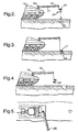
- Figures 1-6 show a method of mine retrieval/neutralisation (and mine neutralisation device) according to the present invention.
- a mine retrieval device according to the present invention is shown.
- a base plate 1 supports a number of spikes 3.
- a polystyrene spacer 5 separates the base plate 1 from an explosive sheet 7 in order to stop shock loading of the base plate 1.
- the thickness of the polystyrene spacer can be varied in order to change the velocity at which the base plate is propelled towards the ground.
- the explosive 7 is connected to a detonator 8.
- a support structure 9 carries the plate, spike and explosive assembly. Means for retrieving the device after use is provided by the retrieval eye 10 which can be connected to a cable and winch.
- Suitable explosives include SX2 which is readily available in sheet form.
- the size of the explosive sheet and its stand-off from the base plate can be varied in order to give the system the necessary energy to penetrate the ground and mine.
- FIG. 2 shows the mine neutralisation/retrieval device of Figure 1 being carried on a supporting boom arm 11 which is in turn attached to a vehicle 13.
- a cable 15 is attached at one end to the mine neutralisation/retrieval device 17 and at the other end to a winch 19.
- the mine neutralisation/retrieval device comprises a number of spikes 21 which are geometrically arranged on the base plate so that the device has a large area of attack and so that the probability of a successful mine attack is increased.
- a number of different configurations for the spikes can be chosen. For example, if the mine's location is accurately known then a single spike variant can be used to attack the periphery of the mine away from the central fuze thereby reducing the probability of accidental mine initiation.
- the device In use, the device is positioned above a mine 23 which has previously been located by, for example, ground penetrating radar or metal detection. The propelling system is then activated and the mine is speared (see Figure 3).
- the speared target can be pulled to the surface, identified and subsequently dealt with.
- the cable 15 and winch 19 system is used to pull the mine 23 from the ground.
- the supporting arm can then be moved to allow the mine neutralisation/retrieval device and the mine itself to be jettisoned in a location 25 from which the mine's destruction can more safely be performed (see Figure 5).
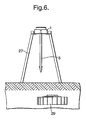
- FIG. 6 shows an alternative way of deploying the mine device according to the invention.
- the figure shows a single spike variant of the device shown in Figure 1 (like numerals denote like features between Figures 1 and 6).
- the spike 3 and base plate 1 are mounted upon a frame 27 such that the spike 3 points vertically downwards.
- the device In use the device is placed above a mine 29 to be removed.
- a robot can conveniently be used to deliver the device to the location of the mine.
- the device is placed such that the spike is aimed slightly away from the centre of the mine 29. This therefore avoids the fuzing system and reduces the risk of accidentally activating the mine when the mine neutralisation device is activated.
Landscapes
- Life Sciences & Earth Sciences (AREA)
- Soil Sciences (AREA)
- Engineering & Computer Science (AREA)
- General Engineering & Computer Science (AREA)
- Drilling And Exploitation, And Mining Machines And Methods (AREA)
- Electrical Discharge Machining, Electrochemical Machining, And Combined Machining (AREA)
- Coating By Spraying Or Casting (AREA)
- Processing Of Solid Wastes (AREA)
- Steroid Compounds (AREA)
- Shovels (AREA)
Claims (8)
- Procédé de récupération d'une mine enterrée comprenant les étapes suivantes :i) localisation d'une mine à récupérer ;ii) propulsion d'un dispositif de récupération de mine en direction de la mine à récupérer, le dispositif de récupération de mine comprenant au moins une pointe de "pénétration de mine" montée sur une plaque d'embase, de telle sorte que la mine est pénétrée et engagée par au moins une pointe, etiii) récupération du dispositif de récupération de mine et de la mine.
- Dispositif de récupération de mine comprenant une plaque d'embase,
au moins une pointe de pénétration de mine, la au moins une pointe étant montée sur une plaque d'embase et pouvant, en utilisation, pénétrer et s'engager dans une mine ;
des moyens de propulsion pouvant, en utilisation, propulser la plaque d'embase et la au moins une pointe en direction d'une mine avec une vitesse suffisante pour permettre la pénétration dans la mine; et
des moyens de récupération de mine permettant de récupérer la plaque d'embase, la au moins une pointe et la mine après l'utilisation du dispositif. - Dispositif de récupération de mine selon la revendication 2, dans lequel les moyens de propulsion sont une feuille explosive.
- Dispositif de récupération de mine selon la revendication 2, dans lequel les moyens de propulsion sont un système à air comprimé.
- Dispositif de récupération de mine selon l'une quelconque des revendications 2 à 5, dans lequel la au moins une pointe est munie de picots.
- Dispositif de récupération de mine selon l'une quelconque des revendications 2 à 6, dans lequel le sommet de la au moins une pointe contient une capsule chimique, ladite capsule pouvant, en utilisation, être brisée pendant la pénétration d'une mine pour libérer un produit chimique capable de déclencher une réaction à faible niveau des composants explosifs de la mine.
- Dispositif de récupération de mine selon la revendication 2, dans lequel le dispositif de récupération comprend un treuil et un câble.
- Dispositif de récupération de mine selon l'une quelconque des revendications 2 à 7, dans lequel la plaque d'embase et la au moins une pointe sont lancées à partir d'un bras de flèche.
Applications Claiming Priority (3)
| Application Number | Priority Date | Filing Date | Title |
|---|---|---|---|
| GB0103844A GB2372235A (en) | 2001-02-16 | 2001-02-16 | Mine neutralisation device |
| GB0103844 | 2001-02-16 | ||
| PCT/GB2002/000488 WO2002066920A1 (fr) | 2001-02-16 | 2002-02-04 | Procede et appareil de localisation de mine |
Publications (2)
| Publication Number | Publication Date |
|---|---|
| EP1360452A1 EP1360452A1 (fr) | 2003-11-12 |
| EP1360452B1 true EP1360452B1 (fr) | 2006-05-10 |
Family
ID=9908891
Family Applications (2)
| Application Number | Title | Priority Date | Filing Date |
|---|---|---|---|
| EP02710177A Expired - Lifetime EP1360452B1 (fr) | 2001-02-16 | 2002-02-04 | Procede et appareil de localisation de mine |
| EP02710175A Expired - Lifetime EP1360451B1 (fr) | 2001-02-16 | 2002-02-04 | Procede et appareil d'excavation de mines |
Family Applications After (1)
| Application Number | Title | Priority Date | Filing Date |
|---|---|---|---|
| EP02710175A Expired - Lifetime EP1360451B1 (fr) | 2001-02-16 | 2002-02-04 | Procede et appareil d'excavation de mines |
Country Status (7)
| Country | Link |
|---|---|
| US (2) | US6883414B2 (fr) |
| EP (2) | EP1360452B1 (fr) |
| AT (2) | ATE293241T1 (fr) |
| DE (2) | DE60203698T2 (fr) |
| ES (1) | ES2236490T3 (fr) |
| GB (1) | GB2372235A (fr) |
| WO (2) | WO2002066920A1 (fr) |
Families Citing this family (12)
| Publication number | Priority date | Publication date | Assignee | Title |
|---|---|---|---|---|
| US6939382B2 (en) | 2002-01-04 | 2005-09-06 | L'oreal S.A. | 4, 5-diaminopyrazole derivatives in dimer form, and use thereof in the oxidation dyeing of keratin fibres |
| GB2383977A (en) * | 2002-01-09 | 2003-07-16 | Qinetiq Ltd | A mineplough incorporating blast absorption means |
| EP1737728A4 (fr) * | 2003-10-14 | 2009-07-08 | Raytheon Co | Systeme de contre mesure de mine |
| IL160343A0 (en) | 2004-02-11 | 2004-07-25 | Rafael Armament Dev Authority | Device and method for neutralizing land mines and the like |
| GB201106126D0 (en) * | 2011-04-11 | 2011-05-25 | Secr Defence | An explosive projectile |
| GB201114805D0 (en) * | 2011-08-26 | 2011-10-12 | Spex Services Ltd | Apparatus for neutralising ground ordinance |
| US8904937B2 (en) | 2012-04-13 | 2014-12-09 | C-2 Innovations Inc. | Line charge |
| RU2500974C1 (ru) * | 2012-08-13 | 2013-12-10 | Общество с ограниченной ответственностью Научно-производственное предприятие "АРМОКОМ-ЦЕНТР" | Щуп для разминирования из полимерных композиционных материалов и способ изготовления щупа для разминирования из полимерных композиционных материалов |
| US10197364B1 (en) * | 2015-03-27 | 2019-02-05 | Gary W Christ | Demining device |
| WO2016157077A2 (fr) * | 2015-03-30 | 2016-10-06 | Director General, Defence Research & Development Organisation (Drdo) | Véhicule et procédé pour détecter et neutraliser un objet incendiaire |
| CA3046819A1 (fr) * | 2016-12-13 | 2018-06-21 | Demine Robotics Inc. | Appareil d'excavation et de neutralisation de mines terrestres et procedes associes |
| US10753712B1 (en) * | 2019-07-29 | 2020-08-25 | The United States Of America As Represented By The Secretary Of The Navy | Extraction system for underground threats |
Family Cites Families (29)
| Publication number | Priority date | Publication date | Assignee | Title |
|---|---|---|---|---|
| US1841802A (en) * | 1929-11-22 | 1932-01-19 | Gettelman Frederick | Picking and tamping device |
| US2806442A (en) * | 1943-10-02 | 1957-09-17 | Temple Velocity Equipment Inc | Mine anchor-line cutter |
| US3844244A (en) * | 1956-06-26 | 1974-10-29 | Us Navy | Mine cable cutter with indicating device |
| US3111927A (en) * | 1961-11-07 | 1963-11-26 | Mine Safety Appliances Co | Cartridge for multiple mine anchor cutter |
| US3326172A (en) * | 1962-11-14 | 1967-06-20 | Louis A Kish | Explosive cutter for moored mine cables |
| US4128071A (en) * | 1963-11-29 | 1978-12-05 | The United States Of America As Represented By The Secretary Of The Navy | Underwater mine chain/cable cutter |
| DE3048752A1 (de) * | 1980-12-23 | 1982-07-15 | Dynamit Nobel Ag, 5210 Troisdorf | Wiederaufnehmbare landmine |
| DE3826731A1 (de) * | 1988-08-05 | 1990-02-08 | Krauss Maffei Ag | Einrichtung zur beseitigung von sprengkoerpern |
| US5743246A (en) * | 1993-09-10 | 1998-04-28 | Earth Resources Corporation | Cannon for disarming an explosive device |
| US5448937A (en) * | 1994-08-12 | 1995-09-12 | Buc; Steven M. | Muzzle launched grapnel hook projectile |
| US5448936A (en) * | 1994-08-23 | 1995-09-12 | Hughes Aircraft Company | Destruction of underwater objects |
| US6216540B1 (en) * | 1995-06-06 | 2001-04-17 | Robert S. Nelson | High resolution device and method for imaging concealed objects within an obscuring medium |
| DE19542377C2 (de) * | 1995-11-14 | 1999-11-25 | Rheinmetall W & M Gmbh | Anordnung zum Räumen von Ankertauminen |
| US5661258A (en) * | 1996-01-25 | 1997-08-26 | The United States Of America As Represented By The Secretary Of The Navy | Air-delivered ordnance explosive mine and obstacle clearance method |
| DE19619135C2 (de) * | 1996-05-11 | 1999-03-25 | Rheinmetall Ind Ag | Unbemanntes gepanzertes Minenräumfahrzeug |
| RU2100751C1 (ru) * | 1996-10-31 | 1997-12-27 | Акционерное общество закрытого типа "АРЛИ спецтехника" | Устройство для разрушения взрывоопасных предметов |
| FR2757622B1 (fr) | 1996-12-23 | 1999-02-05 | Giat Ind Sa | Dispositif de destruction de munitions enterrees ou de deminage |
| DE19714133C2 (de) * | 1997-04-05 | 2000-02-03 | Rheinmetall W & M Gmbh | Verfahren zur Zerstörung von verdeckt verlegten Landminen und Vorrichtung zur Durchführung dieses Verfahrens |
| FR2771165B1 (fr) | 1997-11-14 | 1999-12-31 | Giat Ind Sa | Munition de deminage |
| GB2321880B (en) | 1998-01-08 | 1999-02-24 | Robert George Howes | Anti-personnel mines-clearance-detonation vehicle |
| US5988038A (en) * | 1998-01-22 | 1999-11-23 | Raytheon Company | Method and apparatus for destroying buried objects |
| US6032567A (en) * | 1998-03-16 | 2000-03-07 | The United States Of America As Represented By The Secretary Of The Navy | Surf zone mine clearance |
| JP2000097598A (ja) * | 1998-09-24 | 2000-04-04 | Yasuhito Mogi | 地雷処理装置 |
| US6298763B1 (en) * | 1999-01-20 | 2001-10-09 | The United States Of America As Represented By The Secretary Of The Navy | Explosive device neutralization system |
| CA2288515C (fr) * | 1999-03-08 | 2007-10-23 | Mrel Group Of Companies Limited | Un ensemble et une methode simples pour des operations humanitaires de deminage et l'elimination de materiel explosif |
| US6199793B1 (en) * | 1999-06-11 | 2001-03-13 | Sikorsky Aircraft Corporation | System for deployment and retrieval of airborne towed vehicles |
| DE19944415A1 (de) | 1999-09-16 | 2001-04-12 | John Conner Aitken | Verfahren und Vorrichtung zum gezielten Räumen von in einem Untergrund befindlichen Sprengkörpern |
| US6679176B1 (en) * | 2000-03-21 | 2004-01-20 | Peter D. Zavitsanos | Reactive projectiles for exploding unexploded ordnance |
| US6363828B1 (en) * | 2000-03-30 | 2002-04-02 | The United States Of America As Represented By The Secretary Of The Navy | Shock driven projectile device |
-
2001
- 2001-02-16 GB GB0103844A patent/GB2372235A/en not_active Withdrawn
-
2002
- 2002-02-04 DE DE60203698T patent/DE60203698T2/de not_active Expired - Fee Related
- 2002-02-04 WO PCT/GB2002/000488 patent/WO2002066920A1/fr not_active Ceased
- 2002-02-04 DE DE60211306T patent/DE60211306T2/de not_active Expired - Fee Related
- 2002-02-04 AT AT02710175T patent/ATE293241T1/de not_active IP Right Cessation
- 2002-02-04 EP EP02710177A patent/EP1360452B1/fr not_active Expired - Lifetime
- 2002-02-04 EP EP02710175A patent/EP1360451B1/fr not_active Expired - Lifetime
- 2002-02-04 WO PCT/GB2002/000485 patent/WO2002066919A1/fr not_active Ceased
- 2002-02-04 ES ES02710175T patent/ES2236490T3/es not_active Expired - Lifetime
- 2002-02-04 AT AT02710177T patent/ATE326003T1/de not_active IP Right Cessation
- 2002-02-04 US US10/467,620 patent/US6883414B2/en not_active Expired - Fee Related
- 2002-02-04 US US10/467,619 patent/US7182011B2/en not_active Expired - Fee Related
Also Published As
| Publication number | Publication date |
|---|---|
| WO2002066919A1 (fr) | 2002-08-29 |
| DE60211306D1 (de) | 2006-06-14 |
| GB0103844D0 (en) | 2001-04-04 |
| US6883414B2 (en) | 2005-04-26 |
| WO2002066920A1 (fr) | 2002-08-29 |
| EP1360451B1 (fr) | 2005-04-13 |
| ATE293241T1 (de) | 2005-04-15 |
| ATE326003T1 (de) | 2006-06-15 |
| EP1360451A1 (fr) | 2003-11-12 |
| DE60203698D1 (de) | 2005-05-19 |
| DE60211306T2 (de) | 2007-05-24 |
| US20040069508A1 (en) | 2004-04-15 |
| GB2372235A (en) | 2002-08-21 |
| ES2236490T3 (es) | 2005-07-16 |
| US20040069133A1 (en) | 2004-04-15 |
| DE60203698T2 (de) | 2006-03-02 |
| US7182011B2 (en) | 2007-02-27 |
| EP1360452A1 (fr) | 2003-11-12 |
Similar Documents
| Publication | Publication Date | Title |
|---|---|---|
| EP1360452B1 (fr) | Procede et appareil de localisation de mine | |
| US6701818B1 (en) | Method for seismic exploration of a remote site | |
| US6298763B1 (en) | Explosive device neutralization system | |
| JP3217799B2 (ja) | 埋設された物体を破壊する方法および装置 | |
| CA2314341C (fr) | Procede et appareil servant a enlever des obstacles dans des mines | |
| US4273048A (en) | Surface-launched fuel-air explosive minefield clearance round | |
| US3495532A (en) | Antitank land mine | |
| CA2370722A1 (fr) | Appareil destine a la defense terrestre, maritime et aerienne | |
| US6401591B1 (en) | Neutralization chemical injection penetrator | |
| US6341551B1 (en) | Land mine hunter killer technique | |
| US20040237762A1 (en) | Set defence means | |
| WO2005078375A1 (fr) | Dispositif et procede de neutralisation de mines terrestres et autres | |
| JP2001336899A (ja) | 地雷処理装置 | |
| Lowery | Mine Spike: A Landmine Neutralisation Tool for Combat Scenarios | |
| WO2022090160A1 (fr) | Procédé et système d'élimination de munitions non explosées | |
| FR2732307A1 (fr) | Procede pour mettre hors combat des mines marines, et projectiles et installations de tir pour mettre en oeuvre de tels procedes | |
| JPH11304400A (ja) | 地雷誘爆装置および該地雷誘爆装置を有する地雷除去システム | |
| MXPA00003765A (en) | Method and apparatus for removing obstructions in mines | |
| HK1029392B (en) | Method and apparatus for removing obstructions in mines |
Legal Events
| Date | Code | Title | Description |
|---|---|---|---|
| PUAI | Public reference made under article 153(3) epc to a published international application that has entered the european phase |
Free format text: ORIGINAL CODE: 0009012 |
|
| 17P | Request for examination filed |
Effective date: 20030807 |
|
| AK | Designated contracting states |
Kind code of ref document: A1 Designated state(s): AT BE CH CY DE DK ES FI FR GB GR IE IT LI LU MC NL PT SE TR |
|
| AX | Request for extension of the european patent |
Extension state: AL LT LV MK RO SI |
|
| RIN1 | Information on inventor provided before grant (corrected) |
Inventor name: LOWERY, BRETT ROBERT,QINETIQ Inventor name: PACKARD, THOMAS JAMES,QINETIQ CHERTSEY |
|
| GRAP | Despatch of communication of intention to grant a patent |
Free format text: ORIGINAL CODE: EPIDOSNIGR1 |
|
| GRAS | Grant fee paid |
Free format text: ORIGINAL CODE: EPIDOSNIGR3 |
|
| GRAA | (expected) grant |
Free format text: ORIGINAL CODE: 0009210 |
|
| RIN1 | Information on inventor provided before grant (corrected) |
Inventor name: PACKARD, THOMAS JAMES Inventor name: LOWERY, BRETT ROBERT,QINETIQ |
|
| AK | Designated contracting states |
Kind code of ref document: B1 Designated state(s): AT BE CH CY DE DK ES FI FR GB GR IE IT LI LU MC NL PT SE TR |
|
| PG25 | Lapsed in a contracting state [announced via postgrant information from national office to epo] |
Ref country code: BE Free format text: LAPSE BECAUSE OF FAILURE TO SUBMIT A TRANSLATION OF THE DESCRIPTION OR TO PAY THE FEE WITHIN THE PRESCRIBED TIME-LIMIT Effective date: 20060510 Ref country code: CH Free format text: LAPSE BECAUSE OF FAILURE TO SUBMIT A TRANSLATION OF THE DESCRIPTION OR TO PAY THE FEE WITHIN THE PRESCRIBED TIME-LIMIT Effective date: 20060510 Ref country code: AT Free format text: LAPSE BECAUSE OF FAILURE TO SUBMIT A TRANSLATION OF THE DESCRIPTION OR TO PAY THE FEE WITHIN THE PRESCRIBED TIME-LIMIT Effective date: 20060510 Ref country code: NL Free format text: LAPSE BECAUSE OF FAILURE TO SUBMIT A TRANSLATION OF THE DESCRIPTION OR TO PAY THE FEE WITHIN THE PRESCRIBED TIME-LIMIT Effective date: 20060510 Ref country code: FI Free format text: LAPSE BECAUSE OF FAILURE TO SUBMIT A TRANSLATION OF THE DESCRIPTION OR TO PAY THE FEE WITHIN THE PRESCRIBED TIME-LIMIT Effective date: 20060510 Ref country code: LI Free format text: LAPSE BECAUSE OF FAILURE TO SUBMIT A TRANSLATION OF THE DESCRIPTION OR TO PAY THE FEE WITHIN THE PRESCRIBED TIME-LIMIT Effective date: 20060510 Ref country code: IT Free format text: LAPSE BECAUSE OF FAILURE TO SUBMIT A TRANSLATION OF THE DESCRIPTION OR TO PAY THE FEE WITHIN THE PRESCRIBED TIME-LIMIT;WARNING: LAPSES OF ITALIAN PATENTS WITH EFFECTIVE DATE BEFORE 2007 MAY HAVE OCCURRED AT ANY TIME BEFORE 2007. THE CORRECT EFFECTIVE DATE MAY BE DIFFERENT FROM THE ONE RECORDED. Effective date: 20060510 |
|
| REG | Reference to a national code |
Ref country code: GB Ref legal event code: FG4D |
|
| REG | Reference to a national code |
Ref country code: CH Ref legal event code: EP |
|
| REF | Corresponds to: |
Ref document number: 60211306 Country of ref document: DE Date of ref document: 20060614 Kind code of ref document: P |
|
| REG | Reference to a national code |
Ref country code: IE Ref legal event code: FG4D |
|
| PG25 | Lapsed in a contracting state [announced via postgrant information from national office to epo] |
Ref country code: SE Free format text: LAPSE BECAUSE OF FAILURE TO SUBMIT A TRANSLATION OF THE DESCRIPTION OR TO PAY THE FEE WITHIN THE PRESCRIBED TIME-LIMIT Effective date: 20060810 Ref country code: DK Free format text: LAPSE BECAUSE OF FAILURE TO SUBMIT A TRANSLATION OF THE DESCRIPTION OR TO PAY THE FEE WITHIN THE PRESCRIBED TIME-LIMIT Effective date: 20060810 |
|
| PG25 | Lapsed in a contracting state [announced via postgrant information from national office to epo] |
Ref country code: ES Free format text: LAPSE BECAUSE OF FAILURE TO SUBMIT A TRANSLATION OF THE DESCRIPTION OR TO PAY THE FEE WITHIN THE PRESCRIBED TIME-LIMIT Effective date: 20060821 |
|
| PG25 | Lapsed in a contracting state [announced via postgrant information from national office to epo] |
Ref country code: PT Free format text: LAPSE BECAUSE OF FAILURE TO SUBMIT A TRANSLATION OF THE DESCRIPTION OR TO PAY THE FEE WITHIN THE PRESCRIBED TIME-LIMIT Effective date: 20061010 |
|
| NLV1 | Nl: lapsed or annulled due to failure to fulfill the requirements of art. 29p and 29m of the patents act | ||
| REG | Reference to a national code |
Ref country code: CH Ref legal event code: PL |
|
| ET | Fr: translation filed | ||
| PG25 | Lapsed in a contracting state [announced via postgrant information from national office to epo] |
Ref country code: MC Free format text: LAPSE BECAUSE OF NON-PAYMENT OF DUE FEES Effective date: 20070228 |
|
| PLBE | No opposition filed within time limit |
Free format text: ORIGINAL CODE: 0009261 |
|
| STAA | Information on the status of an ep patent application or granted ep patent |
Free format text: STATUS: NO OPPOSITION FILED WITHIN TIME LIMIT |
|
| 26N | No opposition filed |
Effective date: 20070213 |
|
| PG25 | Lapsed in a contracting state [announced via postgrant information from national office to epo] |
Ref country code: IE Free format text: LAPSE BECAUSE OF NON-PAYMENT OF DUE FEES Effective date: 20070205 |
|
| PG25 | Lapsed in a contracting state [announced via postgrant information from national office to epo] |
Ref country code: GR Free format text: LAPSE BECAUSE OF FAILURE TO SUBMIT A TRANSLATION OF THE DESCRIPTION OR TO PAY THE FEE WITHIN THE PRESCRIBED TIME-LIMIT Effective date: 20060811 |
|
| PGFP | Annual fee paid to national office [announced via postgrant information from national office to epo] |
Ref country code: DE Payment date: 20090219 Year of fee payment: 8 |
|
| PGFP | Annual fee paid to national office [announced via postgrant information from national office to epo] |
Ref country code: GB Payment date: 20090219 Year of fee payment: 8 |
|
| PG25 | Lapsed in a contracting state [announced via postgrant information from national office to epo] |
Ref country code: CY Free format text: LAPSE BECAUSE OF FAILURE TO SUBMIT A TRANSLATION OF THE DESCRIPTION OR TO PAY THE FEE WITHIN THE PRESCRIBED TIME-LIMIT Effective date: 20060510 Ref country code: LU Free format text: LAPSE BECAUSE OF NON-PAYMENT OF DUE FEES Effective date: 20070204 |
|
| PG25 | Lapsed in a contracting state [announced via postgrant information from national office to epo] |
Ref country code: TR Free format text: LAPSE BECAUSE OF FAILURE TO SUBMIT A TRANSLATION OF THE DESCRIPTION OR TO PAY THE FEE WITHIN THE PRESCRIBED TIME-LIMIT Effective date: 20060510 |
|
| PGFP | Annual fee paid to national office [announced via postgrant information from national office to epo] |
Ref country code: FR Payment date: 20090213 Year of fee payment: 8 |
|
| GBPC | Gb: european patent ceased through non-payment of renewal fee |
Effective date: 20100204 |
|
| REG | Reference to a national code |
Ref country code: FR Ref legal event code: ST Effective date: 20101029 |
|
| PG25 | Lapsed in a contracting state [announced via postgrant information from national office to epo] |
Ref country code: FR Free format text: LAPSE BECAUSE OF NON-PAYMENT OF DUE FEES Effective date: 20100301 |
|
| PG25 | Lapsed in a contracting state [announced via postgrant information from national office to epo] |
Ref country code: DE Free format text: LAPSE BECAUSE OF NON-PAYMENT OF DUE FEES Effective date: 20100901 |
|
| PG25 | Lapsed in a contracting state [announced via postgrant information from national office to epo] |
Ref country code: GB Free format text: LAPSE BECAUSE OF NON-PAYMENT OF DUE FEES Effective date: 20100204 |