EP1360897A2 - Vogelkäfig - Google Patents
Vogelkäfig Download PDFInfo
- Publication number
- EP1360897A2 EP1360897A2 EP03010220A EP03010220A EP1360897A2 EP 1360897 A2 EP1360897 A2 EP 1360897A2 EP 03010220 A EP03010220 A EP 03010220A EP 03010220 A EP03010220 A EP 03010220A EP 1360897 A2 EP1360897 A2 EP 1360897A2
- Authority
- EP
- European Patent Office
- Prior art keywords
- cage
- bird
- towers
- cover
- shell
- Prior art date
- Legal status (The legal status is an assumption and is not a legal conclusion. Google has not performed a legal analysis and makes no representation as to the accuracy of the status listed.)
- Granted
Links
Images






Classifications
-
- A—HUMAN NECESSITIES
- A01—AGRICULTURE; FORESTRY; ANIMAL HUSBANDRY; HUNTING; TRAPPING; FISHING
- A01K—ANIMAL HUSBANDRY; AVICULTURE; APICULTURE; PISCICULTURE; FISHING; REARING OR BREEDING ANIMALS, NOT OTHERWISE PROVIDED FOR; NEW BREEDS OF ANIMALS
- A01K31/00—Housing birds
- A01K31/06—Cages, e.g. for singing birds
Definitions
- the invention relates to a bird cage and in particular to various Aspects of cages, the advantages over cages of the prior art exhibit.
- the bird cage is said to be high Percentage of waste caused by a bird or birds in the cage hold back instead of letting the waste be thrown out into the environment.
- a special basic bird cage arrangement which has a Baffle assembly that prevents waste from the bird cage falls out when a bird flaps its wings in the cage.
- the cage also contains corner towers, which also act as protective shields or baffles, to prevent grain shells from being thrown out of the cage when a bird is being fed.
- the Basic arrangement a single drawer that is designed so that the entire Waste generated in the cage falls into it.
- Drawer has a larger area than the floor area of the living space within the Has cage.
- This arrangement not only prevents the waste from the cage is thrown out on the floor, but also prevents the waste from entering the Basic arrangement of the cage falls. Therefore, the owner of the cage only needs that Clean the drawer and do not disassemble the cage to remove both the Basic arrangement as well as to clean the drawer.
- Another aspect of the present invention is the cage like this train that the birds inside can be seen clearly from every angle are, either through the wire mesh that forms the sides of the cage, or through the Towers that form part of the cage frame.
- the Towers made of translucent material, such as. B. transparent or translucent plastic, which create a bay window effect, so that the birds in the cage are clearly seen through the towers in the cage corners can be.
- This construction avoids the prison-like feeling of well-known bird cages, although the wire mesh remains for good ventilation and the cage allows a bird to climb all over the cage.
- feeding sites are for the bird provided that are accessible from outside the cage. It is a Carrier for a bird feeder provided between a first position, in which this serves as a perch for a bird when the feed container is open is located within the cage and is movable to a second position Close the opening in the cage in which the feeding station is attached when the Feed container is pulled out of the inside of the cage.
- a preferred Embodiment with regard to this aspect of the invention are feeding stations in the four towers at the corners of the cages.
- the bird cage is equipped with perches or branches, which can be formed in alternative positions on the towers so that the Bird can either sit closer or farther from the tower walls.
- the rods or branches with a curved configuration and with Fasteners are provided in the fasteners in the Towers or intervene in the food bowls. They bend in one position bent poles away from the towers so that one sitting on the pole Vogel is further away from the tower wall and in an alternative position, in which the Curve is closer to the tower wall where the bird is closer to the tower sitting.
- the tower serves as a window and allows a full view of the bird.
- the wire mesh covering the sides, the front and the back of the bird cage form, are all individually removable.
- the grids are all in for easier production essentially rectangular in shape and snap easily into connectors in the Towers.
- the open configuration resulting from the top grille also improves that Visibility of the interior of the cage, maximizes air circulation, increases the climbing area for the birds, increases the volume of the cage and follows the normal flight path of a bird inside the cage.
- Yet another aspect of the present invention is training and in the operation of a wire mesh door or doors of a maximum size by one easy entry and removal of the bird or birds from the Allow bird cage.
- the doors are still attached so that they are in relation are rotatable on the cage outwards or inwards. If you're after open outside, the wire mesh hangs close to the side of the cage and does not extend far from the cage. everyone avoids this Probability of someone accidentally bumping into the door and either injuring themselves or damaged the cage.
- the ability to fold the wire mesh inwards is particularly beneficial if the bird cage remains open to the bird or the Allowing birds to fly in and out of the cage freely as the Door forms a comfortable landing area within the cage when the bird is in the Cage returns.
- a floor grating is in the Cage available that is held in a removable drawer that is part forms the basic arrangement.
- the floor grille can be removed for cleaning or other purposes.
- the floor grille can only be removed if the cover the drawer is removed, which is delicate and the removal of the birds from the Cage required.
- a unique cage cover which includes a handle with which the cage can be hung from the ceiling.
- the coverage is basically through formed a peripheral frame and the grille.
- the grid forms one Landing area for the bird when it flies around in the room where the cage is is arranged.
- the contours of the cage cover frame are not suitable for the a bird stands on it so that the bird is only on the wire mesh, which causes that waste falls into the cage and is collected in the drawer.
- the cage can be expanded to increase its capacity. This is according to one Embodiment achieved by simply removing the cover assembly of the cage is attached and an additional set of towers is attached, which is essentially are identical to the original towers that are already used for the cage, and the cover on the tops of the additional towers again is attached. Additional grids can be added to the new top areas of the cage be attached to complete the expansion.
- the additional towers may include additional feeding stations and adapters that are used to connect the additional towers to the original towers.
- Another aspect of the present invention is the modular structure of the cage, which enables the cage to be stored and shipped in parts and is easy for the user to assemble and disassemble.
- Another aspect of the present invention is the ability of the Bird cage alone on a floor, on a table or on a suitable one Stand stands, which can also have a dismantled construction.
- the booth according to one aspect of the present invention preferably contains one Storage area for food bags or other material related to the bird cage is used and the stand can be filled with sandbags or water containers to increase its stability.
- the collapsible bird cage 30 shown in the drawings includes in essentially a basic arrangement 40, a cover 42, corner towers 44, Side grille 46, a rear grille 48 and a front grille 50.
- the basic arrangement 40 and the cover 42 together with the Corner towers 44 frame the cage.
- one or more grids are removed to the others To see parts of the arrangement better.
- the cage 30 is on one Stand 54 shown, however, it should be noted that the cage without one Stand can be used on any floor surface, such as B. a table or a floor, or it can be carried from above or it can be used with stands of alternative configurations.
- the various parts mentioned above are described in more detail below explained.
- the basic arrangement 40 is shown in detail in FIG 3-6 and includes a base 60, a shell 66, a Cover 72 and a floor grid 90.
- the base 60 has a bottom wall 62 and a side wall 64 that extends around the sides and back of the bottom wall extend.
- the front 61 of the base 60 is open (not with side walls 64 provided) to allow the shell 66 to enter and exit the base can be pushed.
- the shell 66 includes a peripheral wall 68 that is four Sides of the tray bottom 70.
- the cover 72 forms in this Embodiment an open frame with side parts 74 and front and Back portions 76 and 78.
- Cover 72 rests on base 60 with the top Edges 79 of the side wall 64 of the base and the lower edges 82 of the side, the Interlock front and rear wall parts 74, 76 and 78 of the cover.
- the side parts 84 of the side wall 64 of the base 60 carry themselves upwards extending connecting parts 86, which in openings 88 in the side wall parts 74th of the cover to keep the base and cover connected.
- the connecting parts 86 shown have hook-like flanges 87 which are extend into openings 88, but it should be noted that many others Types of compounds known in the art can be used can, such as B. screws, brackets, etc. and the connections can other than or in addition to the sides of the base 60 and cover 72 become.
- the base 60 and cover 72 are normally not once they are put together.
- the floor grid 90 rests on the Flanges 92 on the rear wall portion 102 of the shell 66 and on the Flanges 93 on the side parts 74 of the cover 72.
- the grid 90 is made a series of parallel wires 94 formed from side to side run in the cage and are 96 through a series of stronger cross wires connected, which extend from front to back.
- the wire mesh 90 is shown in assembled position on the shell 66 and within the base 60 by the Top sides of the front and back portions 98 and 102 of the side wall 68 of the shell kept free which extends the height of the grid 90 when the drawer is fully inserted into the base (see Fig. 6).
- FIGS. 4-6 show in detail how the shell 66 on the base 60 is worn, how the shell opens and closes, and how the bottom grille 90 is removed becomes.
- the grid 90 can be passed through partially pull the tray 66 out of the base assembly 40.
- the Shell bottom 70 has a flat larger area 100, which differs from one rear portion 102 of the peripheral wall 68 extends to the front portion 98 and smoothly into a downward ramp 104 to a point behind the finger grip 106 extends in the front section 98.
- the bottom wall 62 of the base 60 carries ramps 108 on the top 109 near the rear wall 64 (see in FIG 3), with the shell bottom 70 of the shell cooperate so that the shell is raised when fully into the base 60 is inserted and drops a little when the drawer moves a few inches out of the Base 60 is pulled out (see Figures 4 and 5).
- the ramps 108 in the Base 60 act on the shell bottom 70 of the shell and the ramp 104 on the Front of the bowl onto the ledge 112 on the front 110 of the bottom wall 62 the base in such a way that the shell is raised when fully in accordance with the base Fig. 6 is introduced.
- the bowl When the bowl is fully inserted, it touches the floor grille 90 below the top edge of the front portion 98 of the shell so that the grid is not can be removed. From Fig. 4 it can be seen that when the shell a few inches is opened so that the tray bottom slides off the ramps 108 and ramp 104 descends from base ledge 112, shell one occupies a lower position, which releases the floor grille 90 so that it is below the Slide edge 82 of cover 72 and out over the front wall of the tray can. When the shell is fully inserted as in Fig. 6, the bowl moves Front edge 95 of the shell side wall in close proximity to the lower edge 82 of the Cover and floor grille 90 is held in place.
- FIG. 6 From Fig. 6 it can be seen that the front edge 112 of the base bottom wall 62 in a Notch 116 at the front end of ramp 104 engages the shell in the interior retractable position of the base releasably.
- handle 106 overcomes by engaging edge 112 with the notch 116 generated resistance so that the shell and floor grille 90 pulled out or that the tray with the grid completely for cleaning etc. can be removed from the base 60.
- the grid 90 remains on the Guide flanges 93 held, but can be lifted off if the The drawer is pulled out a few inches.
- the construction of the base assembly 40 is intended to prevent bird waste from the Cage can fly out when a bird or birds move in the cage.
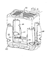
- the formation of the side walls 74, 76 and 78 of the cover 72 together with the side wall 64 of the base 60 and the peripheral wall 68 of the shell form a C-shaped Distraction on the four sides of the base assembly 40 to prevent bird waste in the Keep cage. Any waste whirled around in the cage hits the side walls of the basic arrangement, remains in the basic cage arrangement 40 and becomes not from the cage and onto the floor or other surrounding surfaces thrown out. This feature is clearly shown in Fig. 1. It follows also from Fig.
- Each of the towers 44 at the corners of the cage is preferably transparent Plastic material such as B. polystyrene or other translucent suitable Materials that are either transparent or translucent are made so that a bay window effect is achieved, which allows birds in their cage in their entire area, with an observer seeing the birds at the same time can without the view being impaired by wire mesh.
- the Plastic material can also be colored.
- points each tower 44 has a curved shape that corresponds to the curved recesses 120 corresponds to each of the corners of the base cover 72.
- the bottom edge 122 of each tower is a series of connectors 124 that connect to Recordings 126 on the edges of the curved corners 120 of the cover fit together to releasably hold the towers.
- the top edge 130 of each Tower also carries one or more connectors 132 that are configured with openings 134 the corners of the cover 42, as described in more detail below, interact.
- the cover 42 is substantially rectangular in plan and has front and rear parts 140 and 142 and side parts 144 which together form the Form cover frame.
- the front, rear and side panels 140, 142 and 144 are connected to the rounded corner pieces 146 containing the openings 134 which receive the connectors 132 at the top of the towers.
- FIG. 3a Another embodiment, shown in Figure 3a, includes a single one Connector 132a in the middle of the top of the tower 44a and alignment pins 133 each end of the top of the tower.
- Connector 132a in the middle of the top of the tower 44a and alignment pins 133 each end of the top of the tower.
- complementary recesses 135a are shown to receive connectors 132a and openings, not shown, for receiving the alignment pins.
- a handle 150 Between the middle areas of the front and rear parts 140 and 142 the cover 42 extends a handle 150.
- Fig. 3a is also a hanger 151 shown, which can be connected to the handle so that the cage of can be hung up.
- the front and rear parts 140 and 142 also carry rails 152 (see FIG. 3) that have the front and rear edges 154 pick up the top of the wire mesh 156.
- Grid 156 is preferred rectangular and flat shaped so it is easy to make. If the top Grid 156 inserted into the rails 152, the grid bends slightly from the side Side to a tension between the wire mesh and the rails of the Generate cover so that the grid is held in place.
- the upper grid 156 increases ventilation in the cage, provides a landing area for birds when out from the cage to fly around the room, and offers one Climbing area for birds in the cage.
- the rounded contour of the cover that made up the front and rear portions 140 and 142 is formed, the side portions 144 which Corner pieces 146 and the handle 150 are not platforms for birds outside the cage and they prefer to stay on the grid 156. Since the Birds stand on the grate instead of on the cover, their waste falls through that Grid in the cage and in the shell 66 of the basic arrangement and does not get dirty the surrounding area.
- the cover assembly is preferably molded Plastic such as polystyrene or other suitable material according to the Turrets 44, base 60, shell 66 and cover 72 are formed.
- the front, rear and side panels 140, 142 and 144 together with the corner pieces 146 and the handle 150 may be formed as a unitary structure or alternatively Different parts can be manufactured and assembled separately.
- Each of the towers 44 has a feed station 160, which is shown in FIG Embodiment of FIG. 1 are arranged near the lower end 161.
- the towers carry the stations in openings 162 (see Figures 3 and 7-9).
- Each opening 162 has rails 164 along their sides that pass through a grain drawer 166 Wear outward flanges 168 on each side that are in the rails are slidably received.
- a drawer 166 is substantially U-shaped Platform 170, which carries a grain cup 172. The mug 172, the Grains can be taken out of the drawers for cleaning and filling removed and inserted into it.
- the drawer can be invented by a spring catch 169 on the platform 170 are held, which engages in the bottom edge 162a of the opening 162 when the Drawer is in the outer position shown in FIG. 8.
- the drawer points a curved wall 171 that extends upward from the platform and roughly aligned with the opening when the drawer is in the outer position 8 is located.
- Wall 171 serves as a gate in the opening to prevent that birds can leave the cage when the feed pan 172 is out of the Drawer is removed.
- the feed bowl in turn has an outwardly curved one Wall 173, which corresponds in shape and size to the opening 162, so that then when the bowl is fully inserted into the cage, the drawer with every movement closes the opening 162 on the rails 168 according to FIG. 7.
- the grain shell 172 contains a grain container 175 that is partially curved by the front Wall 173 and a shorter inner wall 177 are formed along the side walls 179 is.
- a spring hook 183 under the container bottom wall 181 and engages in the bottom edge of the opening when the drawer and the grain bowl are fully in opening 162 is inserted into tower 44 and holds drawer 166 and Grain shell 172 releasably in position.
- the positions of the drawer and the bowl are in the closed and open position in Figures 7 and 8 shown. 8, the shell 172 is pulled out of the tower opening 162 shown so that it can be filled with feed.
- the drawer 166 moves itself with the tray on the rails 164.
- the tray 172 can be removed from the drawer can be moved out by loosening the coupling that holds the parts together becomes.
- the leading edge 177a overlaps Shell 172 a portion of the length of the top edge 171a of wall 171 of the Drawer 166.
- the shell needs only on the Back side to be raised so that the overlapping edge over the top 171a of the wall 171 arrives.
- Other means can also be used, such as e.g. B. snap connections, hooks, clips, etc. to a releasable training of Reach the drawer and bowl.
- the bathing station has side flanges 187 similar to the flanges 168 on the grain shell drawer 166 and has a front wall 189 similar the front wall 173 of the grain container 172, so that the bathing station in the Opening 162 can be attached when the drawer 166 and the grain container 172 are removed.
- the tub 185a is easy for birds in the Containers accessible when the bathing station 185 is inserted in the tower 44. If the birds bathe in it, they can easily be observed through the tower wall.
- the bath preferably contains on its inner edge a perch 185b on which a bird sits when entering or exiting the bath.
- the bathing station 185 can be easily removed from the tower by removing the flanges 187 from the Rails 164 are removed.
- the baffle 300 is made typically from an injection molded plastic sheet with a curved top side 302, which essentially follows and follows the curvature of the tower below widening edges 304 and lugs 306 with columns 308 near the Have bottom edge 310, which engage in the wings 190 of the towers 44 and themselves extend between the wires of the grid next to each side of the tower so that they are held releasably.
- the Grids are removed first and after attaching the shield in the tower again be used.
- the badge can be attached in several ways, e.g. B. with clamps, clips or brackets, either with the tower or the shield are integrally formed and each in one of the adjacent components the cage arrangement intervene.
- the shield is removable to allow for the Facilitate cleaning.
- Fig. 9 shows a perch 178 as shown on the inside of each tower 44 above the opening 162, the drawer 166, the grain container 172 and the Bathing station 185 takes, can be attached.
- the perch 178 is light shown curved and can be either in or out of the inner surface 179 of the tower 44 are attached.
- each carries Perch 178 has a clip 180 at each end 182 that fits into a gap 184 in the Side tabs 186 engages on the edges of the tower 44.
- the tabs are flexible enough that they can be pushed out so that the clips 180 the Perch 178 can be aligned with the columns 184.
- the perch can be reversed to the size of the bird that is housed is to be adjusted.
- the towers 44 are preferably made of transparent plastic observers can be very close and with a clear view of the bird watch when he sits 178 on a perch. It should be emphasized that other connectors are used to secure the perches in the towers can be. It should also be noted that feeding sticks as Part of the feeding container drawer can be designed either as integral part of it or separately and attached to the drawer. The perch should of course be located near the grain container.
- FIG. 11 is a way of attaching the side, front and rear grilles 46, 48 and 50 are shown. It should be noted that many other methods can be used, but only one method is shown. It is high it is desirable that the grids are easily assembled for each type used and can be removed from the cage frame.
- tower wings 190 on each side edge 192 of each of the towers provided, which extends from just below the tabs 186 substantially Extend the underside of the towers 44 (see, for example, FIGS. 2 and 3). With the wings 190 are in one piece a pair of lattice girders 194 and 196 in the form of hooks educated.
- FIGS refers to the door grille 52.
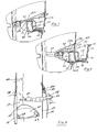
- the door grille 52 is according to one embodiment the invention rotatably held so that it from the closed position of Fig. 12 can be rotated to an open position of Fig. 13, being approximately horizontal is aligned in the cage or brought into an open position of FIG. 14 in which it hangs out of the cage.
- the door along the bottom edge 200 through extensions 202 (See Fig. 3) connected, which is formed as part of the bottom wire 204 of the door grille are.
- the extensions 202 are anchored in recesses 206 that run along the side edges of the front towers 44 above the wings 190 about two thirds of of the base assembly 40 extend.
- the door grille is at the top of the cage is released, the door grille down into one of the open positions of the figures 13 and 14 are rotated.
- the door can be closed in the closed position Button or pawl 208 held by the top wires of the door grille are held and in the cover assembly 42 according to the figures 1 and 12 engages.
- the pawl is rotated to its gap 209 from the edge of the To release front part 140 of the cover when the door is to be opened. If the door is in a position as shown in FIG. 13 in which it is inward opens, a platform is formed in the cage on which a bird can sit, when he returns to the cage through the open door.
- the door opened inwards also causes the formation of a labyrinth for birds to enjoy to climb up and fly around (above and below). If on the sides the cage-like doors are formed, which is another alternative Form embodiment of the invention, there are additional landing and Maze areas for the pleasure of the bird.
- the door or doors can be in a horizontal position in different ways being held. For example, on the edges of the towers next to the door joints in the Path of the side wires of the grid flanges can be provided if this is the Reach horizontal position so that the door or doors are not below this level can be moved. Alternatively, suitable stops in the joints can be installed to achieve horizontal orientation, or the door grilles can contain stops that go below the doors for the same purpose in the Intervene towers.
- Fig. 14 the door grill 52 is shown in the open position, in which it from the Wire link extension 202 hangs down on the outside of the cage. If it is opened in this way, the door does not stand at a considerable distance in the Space around the cage and therefore it is not in a position in which can be triggered accidentally.
- a door can only be provided on the front of the cage the same arrangement described can be used to attach doors to one or on both sides or the back of the cage or shorter fixed grids and Fixed lattice doors are used above as shown.
- the Indian The illustrated embodiment (see FIG. 3) preferably has button 208 shown a contoured handle to grip between thumb and forefinger easier if it is turned to close or open the door. It can other forms of jacks are used to perform a similar function cause such. B. hooks, snap connections, sliding bolts, etc.
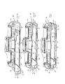
- FIGS. 15-17 show a way of expanding the cage.
- the height of the Cage can be increased slightly, with all components of the basic bird cage, e.g. B. 1, can be used.
- the expansion can be achieved that adapter 230, additional towers 44A that are identical or nearly the same with the towers 44 of the original cage, and additional side rails 46A Rear grille 48A and front grille 232 are used (alternatively one Front grille and a grille door can be used which are essentially the same however longer than those in the basic cage and described there in detail, are trained).
- the cover assembly 42 from the base cage removed by the connectors 132 on the tops of the towers 44 from the Openings 134 in the corners 146 of the cover are removed and on the Adapters 230 are placed on top of the towers, not shown Contain openings that receive the connectors 132 on the top of the towers.
- An adapter 230 for each of the towers is proposed and inserted in FIG Position shown in Fig. 16.
- the adapters 230 themselves have recesses (not shown) that connect the connectors 124 to the bottom of the extension towers 44A so that they snap into place as suggested in Fig. 17 can.
- the Cover assembly 42 on the connectors 132 at the top of the extension towers 44A are snapped on in the same way as the cover arrangement on the Original towers 44 was attached. It should be noted that the upper grid 156 can remain in place in the cover assembly 42 and none additional top grille is required. If the basic structure of the cage on the is composed, the side, rear and front grilles 46A, 48A and 234 can be fixed in place, just like above Basic cage layout described to complete the expansion.
- the adapters 230, the extension towers 44A and the Grid 46A, 48A and 234 as a separate kit from the components of the basic cage can be sold or otherwise distributed. It is also on it to point out that the expansion towers are not identical to the original ones Towers must be, resulting in different side, back and front grilles leads and that indeed the cage with more than one additional floor of towers and grids can be expanded to accommodate a wide range of cage sizes to reach.
- the extension towers 44A can be larger in different heights or smaller than the originals. While the illustrated additional towers also openings for grain containers and drawers in some or all of the extension towers be omitted. It should also be emphasized that in the front and in the sides the extension parts of the cage doors can be provided. A full Compound expanded bird cage is shown in Fig. 18.
- FIGS. 19 to 24 show an embodiment of a cage stand 54 in detail and shown separately from the cage.
- the stand 54 includes a column 242, a base 244 and a platform 246.
- the base plate 244 and the platform 246 can be identical, but to one another vice versa.
- the upper platform 246 can be smaller than the base plate 244 and they do not have to be the same.
- the column 242 in FIG. 20 is composed of four components 248 shown that they are identical in the illustrated embodiment, but in different positions are oriented when they form a pillar are composed.
- Base 244, platform 246 and Components 248 are preferably made from molded plastic parts.
- the Components 248 are each substantially semicircular or in cross-section U-shaped and gradually increasing from the smaller to the smaller larger ends 250 or 252.
- the smaller end 250 of each component 248 includes various fasteners 252 that extend downward when attached the smaller diameter end are oriented in the lower position. These are are configured to engage flanges 254 in base 244 to to hold the lower components on the base plate.
- Two components 248 form the lower half of column 242 and two additional inverted components together form the upper half.
- the side edges 256 of the components 248 carry mounting flanges 258 that are adjacent with corresponding elements Interact components to put two components together.
- the Edges 256 of each component extend approximately one-half the height and the remaining area of each side edge is kept clear so that the adjacent edges result in an opening 260.
- Each component 248 also contains a horizontal wall 262, which is substantially the longer ends 252 of each Half column closes when two adjacent components, as in Fig. 20 shown to be put together.
- the horizontal walls 262 have collars 264 and 266 with smaller and larger diameters.
- the base 244 of the stand has an elliptical opening 270 (see Fig. 20) which receives the flange 272, which the fasteners 252 at the smaller end of the composite component pair, so that the fastener 252 in the Flanges 254 can engage.
- the base plate 244 has a horizontal one Circumferential edge 274, which serves as a secure holder for the stand when it is on is parked on the floor. As suggested in FIG. 19, the base plate 244 can be used Swivel feet 280 may be provided which contain pins 282 which engage in sockets 284 the bottom of the stand. The sockets are in Fig. 19 in the inverted upper platform 246 is shown.
- the complete one Stand in the illustrated embodiment consists of two essentially identical sub-arrangements, as shown in Fig. 21, assuming that the Base plate 244 and platform 246 are identical.
- the two assemblies 290 each consisting of two components 248 and one Base 244 (or platform 246) are assembled together connected so that the larger collars 266 in each subassembly 290 die opposite opposite smaller collar 264.
- the smaller and larger collars are aligned when one Partial arrangement is reversed.
- a uniform structure is created, which ensures a secure stand of the cage cause.
- the walls 262, the collars 264 and 266 carry a tray 292 across the center of the assembled column form, which is accessible through the openings 260.
- FIGS. 23 and 24 show partial designs 294 of a door, each are formed from two doors 296, which over the openings 260 via hooks 298 Grasp edges of tray 292 in the space between walls 262.
- the Doors 296 are linked together so that they are each independent of each other can be opened or closed (see the open position of the doors in Fig. 24 and the closed position in Fig. 19).
- Alternative methods to Attachment of the door 296 can be provided and different Jack arrangement can be used, such as. B. sliding locks, Friction locks, etc. to keep the doors in the closed position.
- the space in column 242 can be used to feed grains or other bird feed as well to accommodate any kind of other cage accessories.
- sand bags or water bags can be placed in column 242 be and especially in the lower half, so the focus of the Arrangement is moved down.
- the platform 246 is specially shaped around the base 60 of the composite Cage.
- the base 60 of the cage can be a number of feet included, such as B. semicircular projections (see Fig. 25) on the underside 302, which lie in one plane and are suitable, on a flat floor surface rest when the cage is used without a stand.
- the same feet may have recesses (not shown) in the top of platform 246 be aligned to ensure a stable connection between the cage and the stand effect when the stand is used.
- the feet can be different Shapes, but they should be suitable to be on a furniture surface stand without being damaged and they should be easily matched with Connections in the stand platform can be aligned so that the cage is light and can be easily removed and attached to the stand as desired can be.
Landscapes
- Life Sciences & Earth Sciences (AREA)
- Birds (AREA)
- Environmental Sciences (AREA)
- Zoology (AREA)
- Animal Husbandry (AREA)
- Biodiversity & Conservation Biology (AREA)
- Housing For Livestock And Birds (AREA)
- Catching Or Destruction (AREA)
- Medicines Containing Material From Animals Or Micro-Organisms (AREA)
Abstract
Description
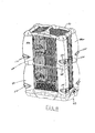
- Fig. 1
- eine perspektivische Frontansicht einer Ausführungsform eines Vogelkäfigs und eines Ständers gemäß einer Ausführungsform der Erfindung,
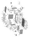
- Fig. 2
- eine Teilexplosionsansicht der Abdeckung, der Türme und der Grundanordnung eines Käfigs von Fig. 1,
- Fig. 3
- eine explosionsperspektivische Ansicht eines Käfigs gemäß den Figuren 1 und 2,
- Fig. 3a
- eine Explosionsansicht eines Teils einer anderen Ausführungsform eines Käfigs gemäß der Erfindung,
- Fig. 4-6
- Teilquerschnittsansichten der Grundanordnung eines Käfigs, die die Ablageanordnung geöffnet, so dass das Bodengitter entfernt werden kann bzw. teilweise geschlossen oder voll geschlossen zeigen,
- Fig. 7, 8
- Teilquerschnittsansichten durch eine Fütterungsstation, die einen Futterbehälter und Halter in ihrer geschlossenen und geöffneten Position zeigen,
- Fig. 9
- eine teilperspektivische Ansicht eines Eckturms, die zeigt, wie eine Sitzstange an der Innenseite einer Ausführungsform der vorliegenden Erfindung angeordnet sein kann,
- Fig. 10
- eine teilperspektivische Ansicht eines Vogelbades, das in d'em Käfig angeordnet ist,
- Fig. 11
- eine teilperspektivische Ansicht eines Vogelkäfigs, die das in dem Käfig befestigte Vogelbad und ein oberhalb des Bades angebrachtes Badeschild zeigt,
- Fig. 12 - 14
- Teilquerschnittsansichten des Vogelkäfigs, die das Türgitter in geschlossener, nach innen geöffneter oder nach außen geöffneten Positionen zeigen,
- Fig. 15 - 17
- perspektivische Ansichten des Käfigs, die eine Art zeigen, durch die der Käfig erweitert oder mit vergrößerter Kapazität versehen werden kann,
- Fig. 18
- eine perspektivische Ansicht einer voll aufgebauten erweiterten Konfiguration des Käfigs,
- Fig. 19
- eine perspektivische Ansicht eines Ständers für einen Käfig gemäß einem anderen Aspekt der Erfindung,
- Fig. 20 - 22
- perspektivische Ansichten eines Ständers von Fig. 19 ohne Türen, die die Art zeigen, in der der Ständer zusammengesetzt wird,
- Fig. 23, 24
- teilperspektivische Ansichten eines Ständers, die die Art zeigen, wie die Türen auf dem Ständer zusammengesetzt werden, und
- Fig. 25
- eine Teilquerschnittsansicht einer anderen Ausführungsform einer Grundanordnung eines Käfigs gemäß der Erfindung.
- 30
- Vogelkäfig
- 40
- Grundanordnung
- 42
- Abdeckung
- 42a
- Abdeckung
- 44
- Türme
- 44A
- Turm
- 46
- Seitengitter
- 46A
- Seitengitter
- 48
- Rückwandgitter
- 48A
- rückwärtiges Gitter
- 50
- Frontgitter
- 52
- Türgitter
- 54
- Ständer
- 60
- Basis
- 61
- Vorderseite
- 62
- Bodenwand
- 64
- Seitenwand
- 66
- Schale
- 68
- Umfangswand
- 70
- Schalenboden
- 72
- Abdeckung
- 74
- Seitenteil
- 76
- Vorderteil
- 78
- Rückenteil
- 79
- Kante
- 82
- Kante
- 84
- Seitenteil
- 86
- Verbindungsteil
- 87
- Flansch
- 88
- Öffnung
- 90
- Bodengitter
- 92
- Flansch
- 93
- Flansch
- 94
- Drähte
- 95
- Vorderkante
- 96
- Drähte
- 98
- Frontabschnitt
- 100
- Bereich
- 102
- Wandabschnitt
- 104
- Rampe
- 106
- Fingergriff
- 108
- Rampe
- 109
- Oberseite
- 110
- Vorderseite
- 112
- Leiste
- 116
- Kerbe
- 120
- Ausnehmungen
- 122
- Kante
- 124
- Verbinder
- 126
- Aufnahme
- 130
- Kante
- 132
- Verbinder
- 132a
- Verbinder
- 133
- Ausrichtstifte
- 134
- Öffnungen
- 135
- Ausnehmung
- 135a
- Ausnehmung
- 140
- Teil
- 142
- Teil
- 144
- Seitenteil
- 146
- Eckstück
- 146a
- Eckstück
- 150
- Tragegriff
- 151
- Aufhänger
- 152
- Schienen
- 154
- Kante
- 156
- Drahtgitter
- 160
- Futterstation
- 161
- Ende
- 162
- Öffnung
- 162a
- Bodenkante
- 164
- Schienen
- 166
- Schublade
- 168
- Flansch
- 169
- Federklinke
- 170
- Plattform
- 171
- Wand
- 171a
- Oberkante
- 172
- Futter- oder Körnerschale
- 173
- Wand
- 173a
- Griff
- 175
- Körnerbehälter
- 177
- Innenwand
- 177a
- Vorderkante
- 178
- Sitzstange
- 179
- Seitenwand
- 180
- Clip
- 181
- Containerbodenwand
- 182
- Ende
- 183
- Federhaken
- 183a
- Griff
- 183b
- Flansch
- 184
- Spalt
- 185
- Badestation
- 185a
- Wanne
- 185b
- Sitzstange
- 186
- Seitenlasche
- 187
- Flansch
- 189
- Vorderwand
- 190
- Flügel
- 192
- Seitenkante
- 194
- Gitterträger
- 196
- Gitterträger
- 200
- Bodenkante
- 202
- Verlängerung
- 204
- Bodendraht
- 206
- Ausnehmungen
- 208
- Knopf
- 209
- Spalt
- 230
- Adapter
- 232
- Frontgitter
- 234
- Gitter
- 242
- Säule
- 244
- Grundplatte
- 246
- Plattform
- 248
- Komponenten
- 250
- Ende
- 252
- Ende
- 254
- Flansch
- 256
- Seitenränder
- 258
- Befestigungsflansch
- 260
- Öffnung
- 262
- Wand
- 264
- Kragen
- 266
- Kragen
- 270
- Öffnung
- 272
- Flansch
- 274
- Kante
- 280
- Schwenkfuß
- 282
- Stift
- 284
- Buchsen
- 290
- Anordnung
- 292
- Ablage
- 294
- Teilausbildungen
- 298
- Haken
- 300
- Badeschild
- 302
- Unterseite
- 304
- Kante
- 306
- Ansatz
- 308
- Spalte
- 310
- Bodenkante
Claims (22)
- Vogelkäfig mit einer Basis (60), voneinander beabstandeten Türmen (44), die sich vom Umfang der Basis nach oben erstrecken, wobei die Türme (44) aus lichtdurchlässigem Material gebildet sind, um einen Vogel in dem Käfig durch die Türme beobachten zu können, einer mit den Oberseiten der Türme verbindbaren Abdeckung (42), um die Oberseite des Käfigs zu schließen, und mit Gittern (46, 48, 50), die zwischen den Türmen befestigt sind, um den Umfang des Käfigs zu schließen.
- Vogelkäfig nach Anspruch 1, bei dem die Türme transparent sind.
- Vogelkäfig nach Anspruch 1 oder 2, bei dem die Basis, die Türme, die Abdeckung und die Gitter auseinandernehmbar sind.
- Vogelkäfig nach Anspruch 1, 2 oder 3, bei dem wenigstens einer der Türme eine Fütterungsstation (160) mit einer Futterschale enthält, die in und aus dem Turm bewegbar ist, um die Schale von außerhalb des Käfigs ohne Entfernung vom Turm befüllen zu können.
- Vogelkäfig nach Anspruch 4, bei dem die Türme im wesentlichen C-förmig ausgebildet sind und breiter als die Schale sind, um zu vermeiden, dass Futter aus dem Käfig geworfen wird.
- Vogelkäfig nach Anspruch 4, bei dem an den Türmen an der Innenseite des Käfigs entfernbare Sitzstangen ausgebildet sind.
- Vogelkäfig nach einem der Ansprüche 1 - 6, bei dem die Basis eine entfernbare Bodenschale aufweist und oberhalb der Bodenschale ein Bodengitter und eine Abdeckung vorgesehen sind, die die Schublade und das Bodengitter umgeben, um Vogelabfälle in die Bodenschale abzulenken.
- Vogelkäfig nach Anspruch 7, bei dem das Bodengitter in der Schale gehalten wird, wenn die Schale sich in der Basis befindet und aus der Schale entfernbar ist, wenn die Schale wenigstens teilweise aus der Basis herausgezogen ist.
- Vogelkäfig nach Anspruch 8, bei dem die Schale in der Grundanordnung größer als der Bodenbereich des Lebensbereichs eines Vogels im Käfig ist, um Vogelabfall in dem Käfig zu sammeln.
- Vogelkäfig nach einem der Ansprüche 1 - 9, bei dem zusätzliche Türme entfernbar auf die Türme eines Vogelkäfigs aufsetzbar sind, um die Höhe des Käfigs zu erhöhen und die Abdeckung wahlweise entweder auf die ersten vertikalen Türme oder die zusätzlichen Türme aufsetzbar ist.
- Vogelkäfig nach einem der Ansprüche 1 - 10, bei dem die Abdeckung einen Kunststoffrahmen mit vorderen, rückwärtigen und Seitenteilen aufweist, die eine Öffnung mit dem Rahmen bilden und ein Drahtgitter an dem Rahmen befestigt ist, dass die Öffnung schließt.
- Vogelkäfig nach Anspruch 11, bei dem der Rahmen einen Handgriff zum Tragen des Käfigs aufweist.
- Vogelkäfig nach Anspruch 11, bei dem der Rahmen einen Aufhänger zum Aufhängen des Käfigs aufweist.
- Vogelkäfig nach einem der Ansprüche 1 - 13, bei dem eines der Gitter an seiner Oberseite unterhalb der Abdeckung endet und oberhalb des Gitters eine Gittertür zwischen einer offenen und einer geschlossenen Position bewegbar befestigt ist.
- Vogelkäfig nach Anspruch 14, bei dem sich die Gittertür im offenen Zustand in einer horizontalen Position innerhalb des Käfigs befindet.
- Vogelkäfig nach Anspruch 14, bei dem die Tür nach außen kippbar ausgebildet ist und sich nach unten aus dem Käfig parallel zum Frontgitter des Käfigs erstreckt.
- Vogelkäfig nach einem der vorhergehenden Ansprüche, bei dem der Käfig von einem Ständer getragen wird, wobei der Ständer eine Säulenoberseite und einen Bodenbereich aufweist, die im wesentlichen identisch, jedoch übereinander in umgekehrter Anordnung zusammengesetzt sind.
- Vogelkäfig nach Anspruch 17, bei dem jedes der Säulenteile zwei identische Bereiche aufweist, die in ihrem Säulenbereich gleichartig ausgebildet sind.
- Vogelkäfig nach Anspruch 17, bei dem in der Säule eine Speicherkammer ausgebildet ist.
- Vogelkäfig nach Anspruch 11, bei dem der Rahmen der Abdeckung transparent ist.
- Vogelkäfig nach Anspruch 4, bei dem die Futterschale durch eine Schublade gehalten ist, die zwischen einer inneren Stellung, in der die Schale einem Vogel in dem Käfig zugänglich ist, und einer äußeren Position verschiebbar ist, in der die Schale von außerhalb des Käfigs mit Futter gefüllt werden kann.
- Vogelkäfig nach Anspruch 21, bei dem in einer Schublade ein Vogelbad befestigbar ist.
Applications Claiming Priority (2)
| Application Number | Priority Date | Filing Date | Title |
|---|---|---|---|
| US140722 | 1993-10-21 | ||
| US10/140,722 US6715445B2 (en) | 2002-05-07 | 2002-05-07 | Bird cage |
Publications (3)
| Publication Number | Publication Date |
|---|---|
| EP1360897A2 true EP1360897A2 (de) | 2003-11-12 |
| EP1360897A3 EP1360897A3 (de) | 2004-02-25 |
| EP1360897B1 EP1360897B1 (de) | 2005-08-10 |
Family
ID=29249793
Family Applications (1)
| Application Number | Title | Priority Date | Filing Date |
|---|---|---|---|
| EP03010220A Expired - Lifetime EP1360897B1 (de) | 2002-05-07 | 2003-05-07 | Vogelkäfig |
Country Status (4)
| Country | Link |
|---|---|
| US (2) | US6715445B2 (de) |
| EP (1) | EP1360897B1 (de) |
| AT (1) | ATE301389T1 (de) |
| DE (1) | DE50300931D1 (de) |
Families Citing this family (17)
| Publication number | Priority date | Publication date | Assignee | Title |
|---|---|---|---|---|
| US7555996B2 (en) * | 2005-03-23 | 2009-07-07 | J.W. Pet Compnay, Inc. | Birdcage feeder |
| US7665420B2 (en) * | 2002-05-07 | 2010-02-23 | Rolf C. Hagen, Inc. | Bird cage |
| JP4029145B2 (ja) * | 2002-12-04 | 2008-01-09 | 孔雀金網株式会社 | 網籠 |
| CN1287522C (zh) * | 2002-12-20 | 2006-11-29 | 阿尔卑斯电气株式会社 | 具有静电传感器的输入装置 |
| US7171736B1 (en) * | 2003-11-18 | 2007-02-06 | Add Kennon | Portable fire extinguisher stand system |
| JP3910602B2 (ja) * | 2004-04-16 | 2007-04-25 | 株式会社三晃商会 | 小動物用飼育ケース |
| US20060225663A1 (en) * | 2005-03-30 | 2006-10-12 | Michael Chiang | Reptile housing structure |
| USD581602S1 (en) * | 2006-01-09 | 2008-11-25 | Vermont Juvenile Furniture Mfg., Inc. | Pet shelter |
| US20090139460A1 (en) * | 2007-03-13 | 2009-06-04 | Norbert Sonnek | Insulated wood duck house |
| WO2009137689A2 (en) * | 2008-05-07 | 2009-11-12 | Surmodics, Inc. | Delivery of nucleic acid complexes from particles |
| USD607615S1 (en) * | 2008-05-15 | 2010-01-05 | Marvelous Pet Supplies, LLC | Birdcage stand |
| US20090288613A1 (en) * | 2008-05-20 | 2009-11-26 | Ying-Kuan Ho | Pet Cage Assembly |
| US20100236493A1 (en) * | 2009-03-18 | 2010-09-23 | Polly Kazakoff | Birdcage |
| US20100319623A1 (en) * | 2009-04-27 | 2010-12-23 | Trout John F | Squirrel proof feeder |
| US9554553B2 (en) | 2012-03-21 | 2017-01-31 | Central Garden & Pet Company | Animal housing assembly |
| US10973221B1 (en) * | 2016-06-07 | 2021-04-13 | Carolee Caffrey | Bird trapping device |
| US20200100457A1 (en) * | 2018-10-01 | 2020-04-02 | PetSmart Home Office, Inc. | System and method for coupling structural features to a small animal habitat |
Family Cites Families (32)
| Publication number | Priority date | Publication date | Assignee | Title |
|---|---|---|---|---|
| US747494A (en) * | 1903-08-08 | 1903-12-22 | Thomas Jefferson Smith | Receptacle for poultry. |
| US889191A (en) * | 1906-11-12 | 1908-06-02 | William J Wark | Self-cleaning knockdown poultry and merchandise shipping crate. |
| US922020A (en) * | 1908-11-07 | 1909-05-18 | George J Mulzer | Crate. |
| US1651982A (en) * | 1925-12-01 | 1927-12-06 | Art Cage Mfg Company Inc | Bird-cage bottom |
| US1656282A (en) * | 1927-03-10 | 1928-01-17 | Lewicki J Leon | Parrot cage |
| US1821348A (en) * | 1929-05-02 | 1931-09-01 | Andrew B Hendryx Company | Bird cage base |
| US1771492A (en) * | 1929-09-30 | 1930-07-29 | Karlson Albert | Poultry crate |
| US2659345A (en) * | 1950-10-06 | 1953-11-17 | Gustave H Herbert | Combination rest and feeding device for animals |
| US2611338A (en) * | 1951-06-29 | 1952-09-23 | Bernard Edward Co | Plastic bird cage |
| US2769426A (en) * | 1955-06-13 | 1956-11-06 | Russell W Bromley | Parakeet shelter |
| US2914022A (en) * | 1958-01-02 | 1959-11-24 | Alan V Hinton | Bird cage |
| US3100474A (en) * | 1961-09-27 | 1963-08-13 | Schneider Leonard Gabriel | Commode for pets |
| US4319545A (en) * | 1978-04-24 | 1982-03-16 | Teho Sou | Sectional pet cage |
| US4586463A (en) * | 1984-08-01 | 1986-05-06 | The Original Vogelbauer Corporation | Bird cage |
| US4617873A (en) * | 1985-05-13 | 1986-10-21 | Kelmetis George C | Bird cage with fold-down top |
| US4858755A (en) * | 1988-01-22 | 1989-08-22 | Kuivanen Lawrence J | Inflatable display container |
| US5000121A (en) * | 1988-09-20 | 1991-03-19 | Daily Raymond P | Modular cage structure |
| US5010848A (en) * | 1989-10-23 | 1991-04-30 | Rankin William J | Folding travel cage |
| US5152247A (en) * | 1991-09-21 | 1992-10-06 | Brown James S | Feeding tray for birds and method |
| JPH0724046Y2 (ja) * | 1993-02-12 | 1995-06-05 | 孔雀金網株式会社 | 網 籠 |
| US5533466A (en) * | 1994-06-20 | 1996-07-09 | Kohus; Louis M. | Pet habitat with enhanced viewing |
| US5452681A (en) * | 1994-09-13 | 1995-09-26 | Ho; Ying-Kuon | Collapsible animal house assembly |
| US5794567A (en) * | 1997-06-17 | 1998-08-18 | Itzhak; Roni | Cleanable observation cage for reptiles especially snakes |
| US5803018A (en) * | 1997-09-10 | 1998-09-08 | Liou; Jong-Shiaw | Portable knock-down pigeon cage |
| US5996536A (en) * | 1997-10-14 | 1999-12-07 | King; Richard | Bird cage |
| US6460486B1 (en) * | 1997-10-28 | 2002-10-08 | Kennel-Aire, Inc. | Aesthetically appealing square-back animal crate |
| US5957086A (en) * | 1998-02-02 | 1999-09-28 | Gallardo; Gilberto G. | Bird cage |
| US5957087A (en) * | 1998-06-08 | 1999-09-28 | Bonder; Carol P. | Bird feeder with a removable feed drawer |
| US6129052A (en) * | 1999-05-11 | 2000-10-10 | Huang; Candy | Knock-down bird cage |
| US6637322B2 (en) * | 2000-02-29 | 2003-10-28 | Prince Castle Inc. | Apparatus for maintaining cooked food in a ready-to-serve condition using a freestanding cover for food trays |
| US6338318B1 (en) * | 2000-06-09 | 2002-01-15 | Surasak Apichom | Combination cat carrier and cat organizer device and method of use |
| IT249399Y1 (it) * | 2000-06-23 | 2003-05-07 | Marchioro Spa | Struttura di gabbia componibile. |
-
2002
- 2002-05-07 US US10/140,722 patent/US6715445B2/en not_active Expired - Fee Related
-
2003
- 2003-05-07 DE DE50300931T patent/DE50300931D1/de not_active Expired - Lifetime
- 2003-05-07 AT AT03010220T patent/ATE301389T1/de not_active IP Right Cessation
- 2003-05-07 EP EP03010220A patent/EP1360897B1/de not_active Expired - Lifetime
-
2004
- 2004-03-04 US US10/793,157 patent/US6923143B2/en not_active Expired - Fee Related
Also Published As
| Publication number | Publication date |
|---|---|
| US20030209205A1 (en) | 2003-11-13 |
| EP1360897A3 (de) | 2004-02-25 |
| EP1360897B1 (de) | 2005-08-10 |
| US20040194722A1 (en) | 2004-10-07 |
| US6923143B2 (en) | 2005-08-02 |
| US6715445B2 (en) | 2004-04-06 |
| ATE301389T1 (de) | 2005-08-15 |
| DE50300931D1 (de) | 2005-09-15 |
Similar Documents
| Publication | Publication Date | Title |
|---|---|---|
| EP1360897B1 (de) | Vogelkäfig | |
| DE2413176C2 (de) | Spielkäfig für Kleintiere | |
| DE3007767A1 (de) | Verwandelbarer tisch, insbesondere fuer spiele | |
| DE60105340T2 (de) | Tierunterkunft und Zaun für eine solche Tierunterkunft | |
| EP3162197B1 (de) | Faltbare transportbox | |
| DE2322811C2 (de) | Broiler-Mastbatterie | |
| EP0466945B1 (de) | Erweiterbarer Käfig | |
| DE202017106713U1 (de) | Modulares Möbelsystem | |
| DE102011087012A1 (de) | Schiebegitter für eine Aufzuchtvoliere | |
| DE29915244U1 (de) | Vogelfutterhaus | |
| DE202010012275U1 (de) | Kletterschutz-Einrichtung für ein Kinderbett | |
| EP1593301B1 (de) | Pflanztopf-Anordnung | |
| DE3832212A1 (de) | Reisetauben-fangvorrichtung | |
| DE2127369C3 (de) | Tierkäfig | |
| DE2650902A1 (de) | Kleintierbehausung | |
| EP2064945B1 (de) | Taubenhaus | |
| DE2650901A1 (de) | Kleintierbehausung | |
| EP3050433B1 (de) | Sitzeinrichtung für geflügel | |
| DE2540582A1 (de) | Heimtierkaefig | |
| DE2838394A1 (de) | Voliere | |
| EP4458150A1 (de) | Box zum transport und/oder zur unterbringung eines tiers | |
| DE7826139U1 (de) | Bausatz zur erstellung einer voliere | |
| DE102023105789A1 (de) | Kleintierkäfig | |
| DE4125002C2 (de) | Abferkellaufbucht in Schweinestallungen landwirtschaftlicher Betriebe | |
| DE202013004639U1 (de) | Künstliche Kletterwand zum Betrieb über Wasser |
Legal Events
| Date | Code | Title | Description |
|---|---|---|---|
| PUAI | Public reference made under article 153(3) epc to a published international application that has entered the european phase |
Free format text: ORIGINAL CODE: 0009012 |
|
| AK | Designated contracting states |
Kind code of ref document: A2 Designated state(s): AT BE BG CH CY CZ DE DK EE ES FI FR GB GR HU IE IT LI LU MC NL PT RO SE SI SK TR |
|
| AX | Request for extension of the european patent |
Extension state: AL LT LV MK |
|
| PUAL | Search report despatched |
Free format text: ORIGINAL CODE: 0009013 |
|
| AK | Designated contracting states |
Kind code of ref document: A3 Designated state(s): AT BE BG CH CY CZ DE DK EE ES FI FR GB GR HU IE IT LI LU MC NL PT RO SE SI SK TR |
|
| AX | Request for extension of the european patent |
Extension state: AL LT LV MK |
|
| RIC1 | Information provided on ipc code assigned before grant |
Ipc: 7A 01K 31/06 A Ipc: 7A 01K 63/00 B |
|
| 17P | Request for examination filed |
Effective date: 20040330 |
|
| 17Q | First examination report despatched |
Effective date: 20040608 |
|
| AKX | Designation fees paid |
Designated state(s): AT BE BG CH CY CZ DE DK EE ES FI FR GB GR HU IE IT LI LU MC NL PT RO SE SI SK TR |
|
| GRAP | Despatch of communication of intention to grant a patent |
Free format text: ORIGINAL CODE: EPIDOSNIGR1 |
|
| GRAS | Grant fee paid |
Free format text: ORIGINAL CODE: EPIDOSNIGR3 |
|
| GRAA | (expected) grant |
Free format text: ORIGINAL CODE: 0009210 |
|
| AK | Designated contracting states |
Kind code of ref document: B1 Designated state(s): AT BE BG CH CY CZ DE DK EE ES FI FR GB GR HU IE IT LI LU MC NL PT RO SE SI SK TR |
|
| PG25 | Lapsed in a contracting state [announced via postgrant information from national office to epo] |
Ref country code: IT Free format text: LAPSE BECAUSE OF FAILURE TO SUBMIT A TRANSLATION OF THE DESCRIPTION OR TO PAY THE FEE WITHIN THE PRESCRIBED TIME-LIMIT;WARNING: LAPSES OF ITALIAN PATENTS WITH EFFECTIVE DATE BEFORE 2007 MAY HAVE OCCURRED AT ANY TIME BEFORE 2007. THE CORRECT EFFECTIVE DATE MAY BE DIFFERENT FROM THE ONE RECORDED. Effective date: 20050810 Ref country code: FI Free format text: LAPSE BECAUSE OF FAILURE TO SUBMIT A TRANSLATION OF THE DESCRIPTION OR TO PAY THE FEE WITHIN THE PRESCRIBED TIME-LIMIT Effective date: 20050810 Ref country code: RO Free format text: LAPSE BECAUSE OF FAILURE TO SUBMIT A TRANSLATION OF THE DESCRIPTION OR TO PAY THE FEE WITHIN THE PRESCRIBED TIME-LIMIT Effective date: 20050810 Ref country code: SK Free format text: LAPSE BECAUSE OF FAILURE TO SUBMIT A TRANSLATION OF THE DESCRIPTION OR TO PAY THE FEE WITHIN THE PRESCRIBED TIME-LIMIT Effective date: 20050810 Ref country code: NL Free format text: LAPSE BECAUSE OF FAILURE TO SUBMIT A TRANSLATION OF THE DESCRIPTION OR TO PAY THE FEE WITHIN THE PRESCRIBED TIME-LIMIT Effective date: 20050810 Ref country code: SI Free format text: LAPSE BECAUSE OF FAILURE TO SUBMIT A TRANSLATION OF THE DESCRIPTION OR TO PAY THE FEE WITHIN THE PRESCRIBED TIME-LIMIT Effective date: 20050810 Ref country code: TR Free format text: LAPSE BECAUSE OF FAILURE TO SUBMIT A TRANSLATION OF THE DESCRIPTION OR TO PAY THE FEE WITHIN THE PRESCRIBED TIME-LIMIT Effective date: 20050810 Ref country code: CZ Free format text: LAPSE BECAUSE OF FAILURE TO SUBMIT A TRANSLATION OF THE DESCRIPTION OR TO PAY THE FEE WITHIN THE PRESCRIBED TIME-LIMIT Effective date: 20050810 Ref country code: EE Free format text: LAPSE BECAUSE OF FAILURE TO SUBMIT A TRANSLATION OF THE DESCRIPTION OR TO PAY THE FEE WITHIN THE PRESCRIBED TIME-LIMIT Effective date: 20050810 |
|
| REG | Reference to a national code |
Ref country code: GB Ref legal event code: FG4D Free format text: NOT ENGLISH |
|
| REG | Reference to a national code |
Ref country code: CH Ref legal event code: EP |
|
| REG | Reference to a national code |
Ref country code: IE Ref legal event code: FG4D Free format text: LANGUAGE OF EP DOCUMENT: GERMAN |
|
| REF | Corresponds to: |
Ref document number: 50300931 Country of ref document: DE Date of ref document: 20050915 Kind code of ref document: P |
|
| PG25 | Lapsed in a contracting state [announced via postgrant information from national office to epo] |
Ref country code: BG Free format text: LAPSE BECAUSE OF FAILURE TO SUBMIT A TRANSLATION OF THE DESCRIPTION OR TO PAY THE FEE WITHIN THE PRESCRIBED TIME-LIMIT Effective date: 20051110 Ref country code: GR Free format text: LAPSE BECAUSE OF FAILURE TO SUBMIT A TRANSLATION OF THE DESCRIPTION OR TO PAY THE FEE WITHIN THE PRESCRIBED TIME-LIMIT Effective date: 20051110 Ref country code: DK Free format text: LAPSE BECAUSE OF FAILURE TO SUBMIT A TRANSLATION OF THE DESCRIPTION OR TO PAY THE FEE WITHIN THE PRESCRIBED TIME-LIMIT Effective date: 20051110 Ref country code: SE Free format text: LAPSE BECAUSE OF FAILURE TO SUBMIT A TRANSLATION OF THE DESCRIPTION OR TO PAY THE FEE WITHIN THE PRESCRIBED TIME-LIMIT Effective date: 20051110 |
|
| PG25 | Lapsed in a contracting state [announced via postgrant information from national office to epo] |
Ref country code: ES Free format text: LAPSE BECAUSE OF FAILURE TO SUBMIT A TRANSLATION OF THE DESCRIPTION OR TO PAY THE FEE WITHIN THE PRESCRIBED TIME-LIMIT Effective date: 20051121 |
|
| GBT | Gb: translation of ep patent filed (gb section 77(6)(a)/1977) |
Effective date: 20051116 |
|
| PG25 | Lapsed in a contracting state [announced via postgrant information from national office to epo] |
Ref country code: PT Free format text: LAPSE BECAUSE OF FAILURE TO SUBMIT A TRANSLATION OF THE DESCRIPTION OR TO PAY THE FEE WITHIN THE PRESCRIBED TIME-LIMIT Effective date: 20060110 |
|
| NLV1 | Nl: lapsed or annulled due to failure to fulfill the requirements of art. 29p and 29m of the patents act | ||
| PG25 | Lapsed in a contracting state [announced via postgrant information from national office to epo] |
Ref country code: HU Free format text: LAPSE BECAUSE OF FAILURE TO SUBMIT A TRANSLATION OF THE DESCRIPTION OR TO PAY THE FEE WITHIN THE PRESCRIBED TIME-LIMIT Effective date: 20060211 |
|
| PG25 | Lapsed in a contracting state [announced via postgrant information from national office to epo] |
Ref country code: AT Free format text: LAPSE BECAUSE OF NON-PAYMENT OF DUE FEES Effective date: 20060507 |
|
| PG25 | Lapsed in a contracting state [announced via postgrant information from national office to epo] |
Ref country code: BE Free format text: LAPSE BECAUSE OF NON-PAYMENT OF DUE FEES Effective date: 20060531 Ref country code: MC Free format text: LAPSE BECAUSE OF NON-PAYMENT OF DUE FEES Effective date: 20060531 |
|
| PLBE | No opposition filed within time limit |
Free format text: ORIGINAL CODE: 0009261 |
|
| STAA | Information on the status of an ep patent application or granted ep patent |
Free format text: STATUS: NO OPPOSITION FILED WITHIN TIME LIMIT |
|
| 26N | No opposition filed |
Effective date: 20060511 |
|
| PG25 | Lapsed in a contracting state [announced via postgrant information from national office to epo] |
Ref country code: FR Free format text: LAPSE BECAUSE OF FAILURE TO SUBMIT A TRANSLATION OF THE DESCRIPTION OR TO PAY THE FEE WITHIN THE PRESCRIBED TIME-LIMIT Effective date: 20060811 |
|
| EN | Fr: translation not filed | ||
| BERE | Be: lapsed |
Owner name: ROLF C. HAGEN, INC. Effective date: 20060531 |
|
| REG | Reference to a national code |
Ref country code: CH Ref legal event code: PL |
|
| PG25 | Lapsed in a contracting state [announced via postgrant information from national office to epo] |
Ref country code: CH Free format text: LAPSE BECAUSE OF NON-PAYMENT OF DUE FEES Effective date: 20070531 Ref country code: LI Free format text: LAPSE BECAUSE OF NON-PAYMENT OF DUE FEES Effective date: 20070531 |
|
| PG25 | Lapsed in a contracting state [announced via postgrant information from national office to epo] |
Ref country code: LU Free format text: LAPSE BECAUSE OF NON-PAYMENT OF DUE FEES Effective date: 20060507 |
|
| PG25 | Lapsed in a contracting state [announced via postgrant information from national office to epo] |
Ref country code: FR Free format text: LAPSE BECAUSE OF FAILURE TO SUBMIT A TRANSLATION OF THE DESCRIPTION OR TO PAY THE FEE WITHIN THE PRESCRIBED TIME-LIMIT Effective date: 20050810 Ref country code: CY Free format text: LAPSE BECAUSE OF FAILURE TO SUBMIT A TRANSLATION OF THE DESCRIPTION OR TO PAY THE FEE WITHIN THE PRESCRIBED TIME-LIMIT Effective date: 20050810 |
|
| PGFP | Annual fee paid to national office [announced via postgrant information from national office to epo] |
Ref country code: IE Payment date: 20160525 Year of fee payment: 14 Ref country code: GB Payment date: 20160601 Year of fee payment: 14 |
|
| PGFP | Annual fee paid to national office [announced via postgrant information from national office to epo] |
Ref country code: DE Payment date: 20160628 Year of fee payment: 14 |
|
| REG | Reference to a national code |
Ref country code: DE Ref legal event code: R119 Ref document number: 50300931 Country of ref document: DE |
|
| GBPC | Gb: european patent ceased through non-payment of renewal fee |
Effective date: 20170507 |
|
| REG | Reference to a national code |
Ref country code: IE Ref legal event code: MM4A |
|
| PG25 | Lapsed in a contracting state [announced via postgrant information from national office to epo] |
Ref country code: DE Free format text: LAPSE BECAUSE OF NON-PAYMENT OF DUE FEES Effective date: 20171201 Ref country code: IE Free format text: LAPSE BECAUSE OF NON-PAYMENT OF DUE FEES Effective date: 20170507 Ref country code: GB Free format text: LAPSE BECAUSE OF NON-PAYMENT OF DUE FEES Effective date: 20170507 |