EP1360945B1 - Système d'injection de lentille intraoculaire - Google Patents
Système d'injection de lentille intraoculaire Download PDFInfo
- Publication number
- EP1360945B1 EP1360945B1 EP03101217A EP03101217A EP1360945B1 EP 1360945 B1 EP1360945 B1 EP 1360945B1 EP 03101217 A EP03101217 A EP 03101217A EP 03101217 A EP03101217 A EP 03101217A EP 1360945 B1 EP1360945 B1 EP 1360945B1
- Authority
- EP
- European Patent Office
- Prior art keywords
- lens
- optical portion
- eye
- intraocular
- push rod
- Prior art date
- Legal status (The legal status is an assumption and is not a legal conclusion. Google has not performed a legal analysis and makes no representation as to the accuracy of the status listed.)
- Expired - Lifetime
Links
- 238000003780 insertion Methods 0.000 title claims abstract description 98
- 230000037431 insertion Effects 0.000 title claims abstract description 98
- 230000003287 optical effect Effects 0.000 claims abstract description 41
- 239000000463 material Substances 0.000 description 8
- 238000012937 correction Methods 0.000 description 5
- 238000000034 method Methods 0.000 description 5
- 230000002093 peripheral effect Effects 0.000 description 5
- 230000004438 eyesight Effects 0.000 description 4
- 238000001356 surgical procedure Methods 0.000 description 4
- 208000002177 Cataract Diseases 0.000 description 3
- 238000003825 pressing Methods 0.000 description 3
- WOBHKFSMXKNTIM-UHFFFAOYSA-N Hydroxyethyl methacrylate Chemical compound CC(=C)C(=O)OCCO WOBHKFSMXKNTIM-UHFFFAOYSA-N 0.000 description 2
- 238000002513 implantation Methods 0.000 description 2
- 229920003229 poly(methyl methacrylate) Polymers 0.000 description 2
- 239000004926 polymethyl methacrylate Substances 0.000 description 2
- 229920002818 (Hydroxyethyl)methacrylate Polymers 0.000 description 1
- 239000004925 Acrylic resin Substances 0.000 description 1
- 229920000178 Acrylic resin Polymers 0.000 description 1
- VVQNEPGJFQJSBK-UHFFFAOYSA-N Methyl methacrylate Chemical compound COC(=O)C(C)=C VVQNEPGJFQJSBK-UHFFFAOYSA-N 0.000 description 1
- 206010036346 Posterior capsule opacification Diseases 0.000 description 1
- 229920001577 copolymer Polymers 0.000 description 1
- 238000013461 design Methods 0.000 description 1
- 238000011161 development Methods 0.000 description 1
- 230000018109 developmental process Effects 0.000 description 1
- 230000000694 effects Effects 0.000 description 1
- 239000013013 elastic material Substances 0.000 description 1
- 238000004945 emulsification Methods 0.000 description 1
- 230000004305 hyperopia Effects 0.000 description 1
- 201000006318 hyperopia Diseases 0.000 description 1
- 230000002452 interceptive effect Effects 0.000 description 1
- 238000012986 modification Methods 0.000 description 1
- 230000004048 modification Effects 0.000 description 1
- 230000004379 myopia Effects 0.000 description 1
- 208000001491 myopia Diseases 0.000 description 1
- 238000004806 packaging method and process Methods 0.000 description 1
- 229920003023 plastic Polymers 0.000 description 1
- 229920001296 polysiloxane Polymers 0.000 description 1
- 238000002360 preparation method Methods 0.000 description 1
- 239000011347 resin Substances 0.000 description 1
- 229920005989 resin Polymers 0.000 description 1
- 238000005549 size reduction Methods 0.000 description 1
- 230000001954 sterilising effect Effects 0.000 description 1
- 238000004659 sterilization and disinfection Methods 0.000 description 1
- 238000012414 sterilization procedure Methods 0.000 description 1
- 238000003860 storage Methods 0.000 description 1
- 239000012780 transparent material Substances 0.000 description 1
Images


Classifications
-
- A—HUMAN NECESSITIES
- A61—MEDICAL OR VETERINARY SCIENCE; HYGIENE
- A61F—FILTERS IMPLANTABLE INTO BLOOD VESSELS; PROSTHESES; DEVICES PROVIDING PATENCY TO, OR PREVENTING COLLAPSING OF, TUBULAR STRUCTURES OF THE BODY, e.g. STENTS; ORTHOPAEDIC, NURSING OR CONTRACEPTIVE DEVICES; FOMENTATION; TREATMENT OR PROTECTION OF EYES OR EARS; BANDAGES, DRESSINGS OR ABSORBENT PADS; FIRST-AID KITS
- A61F2/00—Filters implantable into blood vessels; Prostheses, i.e. artificial substitutes or replacements for parts of the body; Appliances for connecting them with the body; Devices providing patency to, or preventing collapsing of, tubular structures of the body, e.g. stents
- A61F2/02—Prostheses implantable into the body
- A61F2/14—Eye parts, e.g. lenses or corneal implants; Artificial eyes
- A61F2/16—Intraocular lenses
- A61F2/1662—Instruments for inserting intraocular lenses into the eye
- A61F2/1678—Instruments for inserting intraocular lenses into the eye with a separate cartridge or other lens setting part for storage of a lens, e.g. preloadable for shipping
Definitions
- the present invention relates to systems for inserting a deformable intraocular lens into the eye.
- a deformable intraocular lens examples include a deformable intraocular lens that is inserted into the eye in place of the natural lens when the latter is physically extracted because of cataracts, and a vision correction lens that is inserted into the eye for the sole purpose of vision correction.
- an intraocular lens is inserted into the eye, from which the natural lens has been removed (lens-removed eye), such that the intraocular lens is located in the original position previously occupied by the natural lens and restores vision.
- Various studies on the material and shape of such an intraocular lens have been carried out since Ridley performed the first implantation of an artificial lens in 1949.
- intraocular lens In relation to cataract surgery, a technique for crushing the lens tissue by means of ultrasonic emulsification and suctioning the crushed tissue away has been widely used. This technique enables performance of lens removal surgery to excise an opaque lens through a small incision.
- intraocular lenses themselves have recently been improved.
- Such an improved intraocular lens is disclosed in, for example, Japanese Patent Application Laid-Open ( kokai ) No. 58-146346.
- the optical portion is made of a deformable elastic material. The intraocular lens is inserted, in a folded state, into the eye through a small incision and restored to its original shape within the eye, allowing it to exert its proper lens function.
- the material of the optical portion of such an intraocular lens has been changed gradually from hard polymethyl methacrylate (PMMA) to silicone or soft acrylic resin, which enables the intraocular lens to be inserted into the eye in a folded state.
- PMMA hard polymethyl methacrylate
- intraocular lenses of different shapes have been studied and put into practical use, including an intraocular lens having a circular optical portion and loop-shaped support portions formed of different materials, an intraocular lens whose loop-shaped support portions and optical portion are formed of the same material, and an intraocular lens having plate-shaped support portions.
- the conventional intraocular-lens insertion devices described in (1) and (2) above have the following drawbacks.
- an intraocular lens removed from a package is placed on a placement portion of the device, is deformed, and is then inserted into the eye. Therefore, during actual operation, work for placing the intraocular lens onto the device is needed, resulting in increased time and labour involved in implantation of the intraocular lens.
- an intraocular lens and insertion device must be made germ-free through a sterilization procedure, because they are inserted into the eye through an incision.
- an operator accidentally drops the lens and/or the insertion device onto an unclean surface, such as a floor or table, during the placement operation the germ-free state is lost, and the lens and/or the insertion device becomes unusable.
- the lens when the operator forcedly inserts into the eye an intraocular lens which has been placed on the device improperly, the lens may be broken, or may forcibly fly out from the insertion tube, potentially resulting in damage to the internal tissue of the eye.
- the intraocular-lens insertion device described in (3) above has the following drawbacks.
- the intermediate region of the device can be used as a lens package, work for attaching a cannulae (insertion tube) to the main body must be performed during actual use, because the cannulae (insertion tube) is a member which is formed separately from the main body.
- the patent publication discloses a technique for storing in advance an intraocular lens at the intermediate region located on the centre axis of a push rod, it is difficult to form the intermediate region from a material suitable for storing the lens.
- the push rod interferes with and pushes one of the support potions before coming into contact with the optical portion of the lens, thereby to deform the optical portion.
- FR 2 814 360 discloses an intraocular-lens insertion device in which a lens has a support portion that engages a slot at the end of a pusher rod in a standby position. Pressure is applied to the edge of the optical portion of the lens to deform the lens ready for insertion, and the support portions of the lens are also deformed at this time.
- Preferred embodiments of the present invention aim to provide an insertion system for a deformable intraocular lens, which can store an intraocular lens in a state in which no stress acts on the optical portion, thereby to eliminate the necessity of a conventionally-used lens case for the intraocular lens.
- Another aim is to provide an insertion system for a deformable intraocular lens, which system eliminates or simplifies an operation of placing a lens on an insertion device thereby to save the time involved in the placement operation, while solving drawbacks involved in conventional insertion systems, such as breakage of a lens or improper insertion of a lens, which would otherwise be caused by an improper operation by an operator, and breakage of a lens support portion, which would otherwise be caused by the push rod.
- Still another aim is to provide an insertion system for a deformable intraocular lens, which system enables supply of an intraocular lens and an insertion device in a sterilized state.
- an insertion system for an intraocular lens having a deformable optical portion and at least one loop-shaped support portion for supporting the optical portion within an eye comprising:
- a placement operation for an intraocular lens can be completed by merely moving the lens from the standby position to the insertion position by the moving mechanism. This eliminates a conventionally practiced operation of removing an intraocular lens from a lens case and placing it on the insertion system.
- such an insertion system may prevent deformation or breakage of the lens support portion, which would otherwise occur due to interference with the tip end of the push rod, and prevent erroneous operation involved in the placement operation thereby to improve safety.
- an insertion system is provided with a mechanism for holding an intraocular lens at the standby position in a desired state, deformation of the lens during storage can be prevented. Moreover, when packaging and sterilization for the insertion device are performed in a state in which the lens is held in the insertion device, a completely sterilized intraocular-lens insertion system can be provided.
- the lens moving mechanism comprises interengaging protrusions and depressions that define end positions of the lens moving mechanism corresponding to the standby and insertion positions of the lens.
- the holding means comprises a base member on which the lens moving mechanism is mounted and which engages elastically with an attachment portion of a main body of the insertion system.
- an intraocular lens 20 horizontally stored in a lens holding member 10 serving as holding means for the intraocular lens 20 can be moved between a first or standby position at which the vertical position of the centre of the intraocular lens 20 does not coincide with the centre axis of a push rod 33 of an insertion device 30 and a second or insertion position at which the vertical position of the centre of the intraocular lens 20 coincides with the centre axis of the push rod 33 of the insertion device 30, so that the intraocular lens 20 can be pushed out by the push rod 33.
- a push member 13 is provided as a lens moving mechanism for moving the intraocular lens 20 from the first or standby position to the second or insertion position.
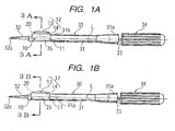
- Figure 1A is a front view of the insertion device 30 to which the lens holding member 10 has been attached and in which the intraocular lens 20 is located at the first or standby position
- Figure 1B is a front view of the insertion device 30 in which the intraocular lens 20 is located at the second or insertion position.
- the system according to the present embodiment is mainly composed of the lens holding member 10, which serves as lens holding means for storing the intraocular lens 20, and the insertion device 30 for inserting the intraocular lens 20 into the eye of a patient.
- the insertion device 30 includes a tubular main body 31, the above-mentioned push rod 33, a pusher mechanism 34, and an attachment portion 35.
- the tubular main body 31 of the insertion device 30 is formed of transparent or semi-transparent plastic or any other suitable material such that the diameter at the base end 31a is larger than that at the tip end 31b.
- the push rod 33 is disposed to be located on the centre axis of the tubular main body 31.
- the pusher mechanism 34 is disposed at the rear end 31a of the tubular main body 31 of the insertion device 30 and is coupled to the rear end of the push rod 33 so as to advance and retract the push rod 33.
- the attachment portion 35 is formed at the tip end 31b of the tubular main body 31 and adapted to receive the lens holding member 10 serving as holding means.
- a tapered insertion tube 32 is formed at the tip end of the attachment portion 35 such that the through hole of the insertion tube 32 is aligned with the centre axis of the tubular main body 31.
- the intraocular lens 20 is pushed out from the tip end 32a of the insertion tube 32 after being deformed to a reduced size.
- the vertical position of the centre of the lens does not coincide with the centre axis of the push rod 33 represented by an alternate long and short dash line L.
- the intraocular lens 20 is stored within the lens holding member 10 at the first or standby position shown in Figure 1A.
- the intraocular lens 20 can be pushed out from the tip end 32a of the insertion tube 32 into the eye through advance movement of the push rod 33 effected by the pusher mechanism 34 provided at the rear end 31a of the tubular main body 31.
- Figures 2A and 2B are views showing an assembled state in which the lens holding member 10 has been attached to the insertion device 30, wherein Figure 2A is an enlarged front view of the insertion device 30 showing a state in which the intraocular lens is located at the first or standby position, and Figure 2B is an enlarged front view of the insertion device 30 showing a state in which the lens is located at the second or insertion position.
- Figure 2C is an enlarged plan view of the lens holding member 10.
- the lens holding member 10 consists of the above-mentioned top member 12 and a base member 11 having a structure suitable for supporting the intraocular lens 20 having loop-shaped support portions 22 made of a material different from that of the optical portion 21.
- the base member 11 has engagement portions 11b which have inclined surfaces 11a of angle ⁇ extending in opposite longitudinal directions and maintaining the angle ⁇ between the optical portion 21 and the support portions 22 of the intraocular lens 20.
- a nipping member 14 of the top member 12 has on its bottom surface 14b inclined surfaces 14a to be mated with the inclined surfaces 11a of the base member 11. After placement of the lens 20 on the base member 11, the top member 12 is placed on the base member 11, so that the support portions 22 of the lens 20 are nipped between the base member 11 and the nipping member 14 of the top member 12.
- a tip end 33a of the push rod 33 is located in an area between the optical portion 21 and the right-hand, loop-shaped support portion 22 as viewed from above in Figures 2A and 2B; i.e. as viewed perpendicular to a plane along which the optical portion 21 of the lens 20 extends.
- Figure 2B shows a state in which the push member 13 of the top member 12 has been pushed downward, whereby the lens 20 is located at the second or insertion position.
- the tip end 33a of the push rod 33 is located between the optical portion 21 and the support portion 22 of the lens 20. Therefore, the tip end 33a of the push rod 33 can push the optical portion 21 of the lens 20 without interfering with the support portion 22.
- FIG. 2C is a plan view of the lens holding member 10.
- the tip end 33a of the push rod 33 is located in the area between the optical portion 21 and the support portion 22 from the beginning. Therefore, when the lens 20 is located at the second or insertion position as a result of the above-described operation of pressing the push member 13, the tip end 33a of the push rod 33 is located on the side toward the optical portion 21 with respect to the right-hand lens support portion 22, whereby interference between the tip end 33a with the support portion 22 can be avoided, and thus, deformation or breakage of the support portion 22 can be prevented.
- the base member 11 of the lens holding member 10 has an opening 11c in the top surface thereof and projections 11e in the vicinity of the lower ends of opposite side walls 11d.
- the projections 11e elastically engage with engagement steps 38 formed in the vicinity of the lower ends of the lateral side surfaces of the attachment portion 35.
- the longitudinal opposite ends of the base member 11 are opened so that the base member 11 has a squarish C-like cross-section.
- the paired engagement portions 11b are formed on the inner surfaces of the side walls 11d to be located at the approximate centre in the vertical direction.
- the engagement portions 11b extend in the longitudinal direction and are adapted to receive the peripheral portions of the optical portion 21 and the support portions 22 of the intraocular lens 20.
- the inclined surfaces 11a each having an inclination angle ⁇ are formed on the engagement portions 11b in order to maintain the angle ⁇ between the optical portion 21 and the support portions 22 of the intraocular lens 20.
- the top member 12 to be inserted into the top surface opening 11c of the base member 11 has the hollow nipping member 14 having a rectangular frame-like shape, and the above-mentioned push member 13 disposed in the nipping member 14 to be movable in the vertical direction.
- the bottom surface 14b of the nipping member 14 has the inclined surfaces 14a corresponding to the inclined surfaces 11a of the engagement portions 11b of the base member 11.
- Upper and lower depressions 14d and 14e are formed at a predetermined interval on each of the inner surfaces 14c of the opposite lateral walls such that the upper depressions 14d are opposed to each other and the lower depressions 14e are opposed to each other.
- the above-mentioned push member 13 is inserted into the opening 14f of the nipping member 14 and is pressed downward in order to move the intraocular lens 20 from the standby position to the insertion position.
- the push member 13 has a head portion 13a of a large diameter and a prism-shaped leg portion 13b.
- Protrusions 13c are formed on the peripheral surface thereof and in the vicinity of the lower end thereof so as to be engaged selectively with the upper depressions 14d or the lower depressions 14e of the nipping member 14. Specifically, at the standby position, the protrusions 13c of the push member 13 engage the depressions 14d, and when the push member 13 is pressed, the protrusions 13c move downward and come into engagement with the depressions 14e.
- a concave surface 13d is formed on the bottom surface of the leg portion 13b, and a ridge 13f for supporting the peripheral portion of the intraocular lens 20 is formed on the concave surface 13d.
- the head portion 13a of the push member 13 of the top member 12 is pressed down such that the intraocular lens 20 whose peripheral portion is partially nipped by the base member 11 and the top member 12 of the lens holding member 10 is moved to a lens movement portion 39 of the attachment portion 35.
- the lens movement portion 39 has a shape of a concavely-curved groove.
- the vertical position of the centre of the lens 20 coincides with the centre axis of the push rod 33 substantially.
- the intraocular lens 20 is moved within the space 15 of the lens movement portion 39 in a direction perpendicular to the page of Figure 3B, passed through the insertion tube 32 provided integrally with the attachment portion 35, and is then pushed into the eye.
- the intraocular lens 20 having been moved to the lens movement portion 39 is prevented from reassuming its original shape, and reliable positioning is effected.
- the lens holding member 10 is preferably formed of transparent or semi-transparent material, which allows an operator to check whether the lens 20 has been moved to the lens movement portion 39.
- the push member 13 of the top member 12 provides two functions; i.e. the function for moving the lens 20 downward and the function for forming the lens movement space 15 in cooperation with the attachment portion 35.
- the lens holding member 10 of the embodiment - which consists of the base member 11 and the top member 12 including the nipping member 14 and the push member 13 - functions as a portion of the mechanism of the insertion device 30 upon attachment thereto.
- the tubular main body 31 of the insertion device 30 and the lens holding member 10 are assembled in order to complete the insertion device 30.
- the base member 11 may be formed integrally with the attachment portion 35 of the tubular main body 31.
- the top member 12 may be formed integrally with the base member 11 such that the top member 12 is connected to one end portion of the upper surface of the base member 11 via a hinge.
- a portion of deforming means for deforming the intraocular lens 20 to a reduced size is formed integrally with the lens holding member 10.
- the lens movement portion 39 of the attachment portion 35 when the lens is moved to the lens movement portion 39 of the attachment portion 35, the lens is deformed to a reduced size.
- This size reduction is achieved by three design features; i.e. the lens movement portion 39 being formed into a form of a curved groove, the lens 20 being moved whilst being pressed toward the lens movement portion 39 by the top member 12, and the dimension J of the lens movement portion 39 being smaller than the dimension K of the lens 20.
- the above-described attachment method is preferable, because an operator can perform the operation of moving the intraocular lens 20 from the first or standby position to the second or insertion position by pressing the push member 13 of the lens holding member 10 from above and inserting the lens 20 from the insertion device 30 into the eye, while holding the insertion device 30, which is larger and easier to hold than the lens holding member 10.
- the lens holding member 10 and the insertion tube 32 form deforming means for deforming the intraocular lens 20.
- the configuration of the device may be modified to assume various configurations; e.g. a configuration such that only the lens holding member 10 is used to deform the intraocular lens 20 to a small size suitable for insertion into the eye, and the thus-deformed lens 20 is passed through the insertion tube 32 and inserted into the eye; and a configuration such that deforming means is not provided on the lens holding member 10, but is provided on the insertion tube 32.
- centre of the intraocular lens 20 refers to the centre in the thickness direction located on the optical axis of the optical portion 21.
Landscapes
- Health & Medical Sciences (AREA)
- Ophthalmology & Optometry (AREA)
- Cardiology (AREA)
- Oral & Maxillofacial Surgery (AREA)
- Transplantation (AREA)
- Engineering & Computer Science (AREA)
- Biomedical Technology (AREA)
- Heart & Thoracic Surgery (AREA)
- Vascular Medicine (AREA)
- Life Sciences & Earth Sciences (AREA)
- Animal Behavior & Ethology (AREA)
- General Health & Medical Sciences (AREA)
- Public Health (AREA)
- Veterinary Medicine (AREA)
- Prostheses (AREA)
Claims (3)
- Dispositif d'insertion pour une lentille intraoculaire (20) ayant une partie optique (21) déformable et au moins une partie (22) de support en forme de boucle, pour supporter la partie (21) optique dans un oeil, le dispositif comprenant :- des moyens de maintien (10) pour maintenir la lentille intraoculaire (20) en une position d'attente dans laquelle aucun stress n'agit sur la partie optique (21) de la lentille (20) ;- des moyens de déformation (10,32) pour déformer la lentille (20) en une taille réduite ;- un tube (32) d'insertion à travers lequel la lentille déformée (20) est insérée dans l'oeil ;- un mécanisme de poussée (34) ayant une tige de poussée (33) pour pousser la lentille (20) au travers du tube d'insertion (32) le long d'un axe de celui-ci, pour ainsi insérer la lentille (20) dans l'oeil:Caractérisé en ce que :- Les moyens de maintien (20) sont disposés pour maintenir la lentille (20) dans la position d'attente de façon que la partie (21) d'optique de la lentille (20) soit espacée de l'axe du tube d'insertion (32) et la lentille (20) est espacée de la tige de poussée (33), avec une extrémité pointue (33a) de la toute extrémité (33a) disposée entre la partie optique (21) et la partie de support (22) de la lentille (20) comme montré perpendiculairement à un plan le long duquel la partie optique (21) s'étend ;- Un mécanisme de déplacement de lentille (13) est disposé pour déplacer la lentille (20) transversalement par rapport au plan le long du quelle la partie tige (21) s'étend à partir de la position d'attente en une position d'insertion en laquelle le mécanisme (34) de poussée peut pousser et insérer la lentille (20) dans l'oeil ;- La toute extrémité (33a) de la tige de poussée (33) reste hors engagement de la lentille (20) et est disposée entre la partie optique (21) et la partie support (22) de la lentille (20), lorsque la lentille (20) est déplacée vers la position d'insertion par le mécanisme de déplacement de lentille (13).
- Dispositif d'insertion selon la revendication 1, caractérisé en ce que le mécanisme (13) de déplacement de lentille comporte des éléments en saillie (13c) en inter engagement et des dépressions (14d, 14e) qui définissent des positions terminales du mécanisme (13) de déplacement de lentilles correspondant aux positions d'attente et d'insertion de la lentille (20).
- Dispositif d'insertion selon la revendication 1 ou 2, caractérisé en ce que les moyens de maintien (10) comportent un élément de base (11) sur lequel le mécanisme (13) de déplacement de lentilles est monté et qui prend prise élastiquement (11e, 38) avec une partie d'attachement (35) d'un corps principal (31) du dispositif d'insertion.
Applications Claiming Priority (2)
| Application Number | Priority Date | Filing Date | Title |
|---|---|---|---|
| JP2002133180A JP2003325570A (ja) | 2002-05-08 | 2002-05-08 | 眼内挿入用レンズの挿入システム |
| JP2002133180 | 2002-05-08 |
Publications (2)
| Publication Number | Publication Date |
|---|---|
| EP1360945A1 EP1360945A1 (fr) | 2003-11-12 |
| EP1360945B1 true EP1360945B1 (fr) | 2006-11-29 |
Family
ID=29244116
Family Applications (1)
| Application Number | Title | Priority Date | Filing Date |
|---|---|---|---|
| EP03101217A Expired - Lifetime EP1360945B1 (fr) | 2002-05-08 | 2003-05-02 | Système d'injection de lentille intraoculaire |
Country Status (6)
| Country | Link |
|---|---|
| US (1) | US20030212407A1 (fr) |
| EP (1) | EP1360945B1 (fr) |
| JP (1) | JP2003325570A (fr) |
| CN (1) | CN100477976C (fr) |
| AT (1) | ATE346570T1 (fr) |
| DE (1) | DE60309960T2 (fr) |
Cited By (1)
| Publication number | Priority date | Publication date | Assignee | Title |
|---|---|---|---|---|
| US7901414B2 (en) | 2001-12-12 | 2011-03-08 | Ioltechnologie-Production | Cassette and injector for flexible intraocular lens and method for injecting such lenses |
Families Citing this family (41)
| Publication number | Priority date | Publication date | Assignee | Title |
|---|---|---|---|---|
| EP1832247B1 (fr) | 2004-12-27 | 2015-06-24 | Hoya Corporation | Dispositif d'implantation de lentille intraoculaire |
| US8545512B2 (en) | 2005-01-26 | 2013-10-01 | Hoya Corporation | Intraocular lens insertion device |
| JP4836046B2 (ja) | 2005-02-24 | 2011-12-14 | Hoya株式会社 | 眼内レンズ挿入器具 |
| WO2007037223A1 (fr) | 2005-09-28 | 2007-04-05 | Hoya Corporation | Instrument pour insérer un cristallin artificiel |
| JP4877643B2 (ja) | 2005-12-08 | 2012-02-15 | Hoya株式会社 | 眼内レンズ挿入用器具 |
| EP1972306A4 (fr) | 2006-01-13 | 2012-11-28 | Hoya Corp | Instrument permettant d'introduire une lentille intraoculaire |
| JP4727497B2 (ja) * | 2006-05-17 | 2011-07-20 | スター・ジャパン株式会社 | 眼内挿入用レンズの挿入器具 |
| JP5236637B2 (ja) | 2007-05-30 | 2013-07-17 | Hoya株式会社 | 眼内レンズ挿入器具及び眼内レンズ挿入装置 |
| WO2008149795A1 (fr) | 2007-05-30 | 2008-12-11 | Hoya Corporation | Outil utilisé pour l'insertion d'une lentille intraoculaire |
| US20080312661A1 (en) * | 2007-06-12 | 2008-12-18 | Downer David A | Lens Injector Lumen Tip for Wound Assisted Delivery |
| JP5086713B2 (ja) | 2007-07-11 | 2012-11-28 | Hoya株式会社 | 眼内レンズ挿入器具 |
| JP5301809B2 (ja) * | 2007-11-01 | 2013-09-25 | 株式会社ニデック | 眼内レンズ挿入器具 |
| JP5086062B2 (ja) | 2007-12-29 | 2012-11-28 | 株式会社ニデック | 眼内レンズ挿入器具 |
| JP5254669B2 (ja) | 2008-06-05 | 2013-08-07 | Hoya株式会社 | 眼内レンズ挿入器具及びカートリッジ |
| JP5470753B2 (ja) | 2008-06-17 | 2014-04-16 | Hoya株式会社 | 眼内レンズ挿入器具 |
| US8273122B2 (en) | 2008-06-23 | 2012-09-25 | Abbott Medical Optics Inc. | Pre-loaded IOL insertion system |
| JP5323420B2 (ja) | 2008-08-21 | 2013-10-23 | Hoya株式会社 | 眼内レンズ挿入器具 |
| JP5416379B2 (ja) | 2008-09-04 | 2014-02-12 | Hoya株式会社 | 眼内レンズ挿入器具 |
| CN102307543B (zh) | 2009-01-07 | 2015-10-21 | Hoya株式会社 | 眼内透镜插入器具 |
| JP5735531B2 (ja) | 2010-04-08 | 2015-06-17 | Hoya株式会社 | 眼内移植片挿入器具 |
| JP5511530B2 (ja) | 2010-06-10 | 2014-06-04 | Hoya株式会社 | 眼内レンズ挿入装置 |
| US9687340B2 (en) | 2010-08-24 | 2017-06-27 | Abbott Medical Optics Inc. | Protective cap for an insertion device and other insertion device features |
| CN103491907B (zh) * | 2011-04-28 | 2015-07-22 | 株式会社尼德克 | 眼内晶体植入器具 |
| JP5807394B2 (ja) | 2011-05-31 | 2015-11-10 | 株式会社ニデック | 眼内レンズ挿入器具 |
| JP5807395B2 (ja) * | 2011-05-31 | 2015-11-10 | 株式会社ニデック | 眼内レンズ挿入器具 |
| JP5874351B2 (ja) * | 2011-11-29 | 2016-03-02 | 株式会社ニデック | 眼内レンズ挿入システム |
| CN104379092B (zh) | 2012-06-04 | 2016-12-14 | 爱尔康制药有限公司 | 眼内透镜插入器 |
| CA3078098C (fr) | 2012-06-12 | 2022-03-15 | Alcon Inc. | Injecteur de gaz intra-oculaire |
| JPWO2015012312A1 (ja) * | 2013-07-24 | 2017-03-02 | 興和株式会社 | 眼内レンズの挿入器具 |
| CA2944513C (fr) | 2014-04-04 | 2022-07-05 | Jack R. Auld | Dispositif d'insertion de lentille intra-oculaire |
| AU2016324545A1 (en) | 2015-09-16 | 2018-04-12 | Hoya Corporation | Intraocular lens insertion tool |
| JP6646987B2 (ja) | 2015-09-16 | 2020-02-14 | Hoya株式会社 | 眼内レンズ挿入器具 |
| US10172706B2 (en) | 2015-10-31 | 2019-01-08 | Novartis Ag | Intraocular lens inserter |
| US11033382B2 (en) | 2016-06-28 | 2021-06-15 | Hoya Corporation | Intraocular lens injector |
| WO2018003853A1 (fr) | 2016-06-28 | 2018-01-04 | Hoya株式会社 | Instrument d'insertion de lentille intraoculaire |
| US11000367B2 (en) | 2017-01-13 | 2021-05-11 | Alcon Inc. | Intraocular lens injector |
| JP7162443B2 (ja) | 2018-05-16 | 2022-10-28 | Hoya株式会社 | 容器付き眼内リング挿入器 |
| JP7162445B2 (ja) | 2018-05-25 | 2022-10-28 | Hoya株式会社 | 眼内レンズ挿入器 |
| US11224537B2 (en) | 2018-10-19 | 2022-01-18 | Alcon Inc. | Intraocular gas injector |
| JP7327956B2 (ja) | 2019-03-13 | 2023-08-16 | Hoya株式会社 | 眼内レンズ挿入器具 |
| CN120616845B (zh) * | 2025-04-24 | 2026-02-10 | 高视泰靓医疗科技有限公司 | 导入头及预装式人工晶状体植入系统 |
Family Cites Families (8)
| Publication number | Priority date | Publication date | Assignee | Title |
|---|---|---|---|---|
| US4573998A (en) | 1982-02-05 | 1986-03-04 | Staar Surgical Co. | Methods for implantation of deformable intraocular lenses |
| JPH0732791B2 (ja) | 1991-06-13 | 1995-04-12 | キヤノンスター株式会社 | 眼内レンズの移植器具 |
| JP3459664B2 (ja) * | 1993-07-15 | 2003-10-20 | キヤノンスター株式会社 | 変形可能な眼内レンズの挿入器具 |
| JP3412103B2 (ja) | 1993-07-15 | 2003-06-03 | キヤノンスター株式会社 | 変形可能な眼内挿入用レンズの挿入器具 |
| EP1338254B1 (fr) | 1994-08-05 | 2008-12-03 | Bausch & Lomb Incorporated | Procédé d'emballage de lentille intraoculaire |
| US5947975A (en) * | 1997-03-07 | 1999-09-07 | Canon Staar Co., Inc. | Inserting device for deformable intraocular lens |
| JP3944555B2 (ja) * | 1999-10-06 | 2007-07-11 | キヤノンスター株式会社 | 眼内挿入用レンズの挿入システム |
| FR2814360B1 (fr) * | 2000-09-28 | 2002-12-27 | Corneal Ind | Injecteur d'implant intraoculaire souple |
-
2002
- 2002-05-08 JP JP2002133180A patent/JP2003325570A/ja active Pending
- 2002-09-27 US US10/256,342 patent/US20030212407A1/en not_active Abandoned
-
2003
- 2003-04-18 CN CN03110639.0A patent/CN100477976C/zh not_active Expired - Fee Related
- 2003-05-02 EP EP03101217A patent/EP1360945B1/fr not_active Expired - Lifetime
- 2003-05-02 DE DE60309960T patent/DE60309960T2/de not_active Expired - Lifetime
- 2003-05-02 AT AT03101217T patent/ATE346570T1/de not_active IP Right Cessation
Cited By (1)
| Publication number | Priority date | Publication date | Assignee | Title |
|---|---|---|---|---|
| US7901414B2 (en) | 2001-12-12 | 2011-03-08 | Ioltechnologie-Production | Cassette and injector for flexible intraocular lens and method for injecting such lenses |
Also Published As
| Publication number | Publication date |
|---|---|
| EP1360945A1 (fr) | 2003-11-12 |
| US20030212407A1 (en) | 2003-11-13 |
| JP2003325570A (ja) | 2003-11-18 |
| DE60309960T2 (de) | 2007-09-20 |
| ATE346570T1 (de) | 2006-12-15 |
| CN1456135A (zh) | 2003-11-19 |
| DE60309960D1 (de) | 2007-01-11 |
| CN100477976C (zh) | 2009-04-15 |
Similar Documents
| Publication | Publication Date | Title |
|---|---|---|
| EP1360945B1 (fr) | Système d'injection de lentille intraoculaire | |
| EP1360947B1 (fr) | Système d'insertion de lentille intraoculaire | |
| US20010007942A1 (en) | Insertion system for intraocular lens | |
| US6468282B2 (en) | Insertion system for intraocular lens | |
| US7014641B2 (en) | Insertion device for intraocular lens | |
| JP5470753B2 (ja) | 眼内レンズ挿入器具 | |
| US7131976B2 (en) | Insertion device for intraocular lens | |
| US6355046B2 (en) | Inserting device for deformable intraocular lens | |
| TWI608852B (zh) | 人工水晶體用注射器 | |
| JP6027535B2 (ja) | 眼内レンズの挿入器具 | |
| CN108882977A (zh) | 复曲面眼内透镜及眼内透镜插入设备 | |
| JP2003325568A (ja) | 眼内挿入用レンズの挿入システム | |
| US6622855B1 (en) | Intraocular lens case | |
| CN100488472C (zh) | 用于眼内插入用晶状体的插入装置 | |
| JP3088806B2 (ja) | 眼内レンズの挿入固定用補助具 | |
| HK1047690A1 (en) | Insertion system for intraocular lens | |
| EP1275354B1 (fr) | Lentille intraoculaire | |
| JP3779859B2 (ja) | 眼内挿入用レンズの挿入システム | |
| JP3893448B2 (ja) | 眼内挿入用レンズの挿入システム | |
| TW201919551A (zh) | 人工水晶體植入器具 | |
| JP2005246104A (ja) | 眼内挿入用レンズの挿入器具 | |
| JP2004344478A (ja) | 眼内挿入用レンズの挿入システム |
Legal Events
| Date | Code | Title | Description |
|---|---|---|---|
| PUAI | Public reference made under article 153(3) epc to a published international application that has entered the european phase |
Free format text: ORIGINAL CODE: 0009012 |
|
| AK | Designated contracting states |
Kind code of ref document: A1 Designated state(s): AT BE BG CH CY CZ DE DK EE ES FI FR GB GR HU IE IT LI LU MC NL PT RO SE SI SK TR |
|
| AX | Request for extension of the european patent |
Extension state: AL LT LV MK |
|
| 17P | Request for examination filed |
Effective date: 20040512 |
|
| 17Q | First examination report despatched |
Effective date: 20040608 |
|
| AKX | Designation fees paid |
Designated state(s): AT BE BG CH CY CZ DE DK EE ES FI FR GB GR HU IE IT LI LU MC NL PT RO SE SI SK TR |
|
| GRAP | Despatch of communication of intention to grant a patent |
Free format text: ORIGINAL CODE: EPIDOSNIGR1 |
|
| RIN1 | Information on inventor provided before grant (corrected) |
Inventor name: KIKUCHI, TOSHIKAZU Inventor name: KOBAYASHI, KENICHI |
|
| GRAS | Grant fee paid |
Free format text: ORIGINAL CODE: EPIDOSNIGR3 |
|
| GRAA | (expected) grant |
Free format text: ORIGINAL CODE: 0009210 |
|
| AK | Designated contracting states |
Kind code of ref document: B1 Designated state(s): AT BE BG CH CY CZ DE DK EE ES FI FR GB GR HU IE IT LI LU MC NL PT RO SE SI SK TR |
|
| PG25 | Lapsed in a contracting state [announced via postgrant information from national office to epo] |
Ref country code: IT Free format text: LAPSE BECAUSE OF FAILURE TO SUBMIT A TRANSLATION OF THE DESCRIPTION OR TO PAY THE FEE WITHIN THE PRESCRIBED TIME-LIMIT;WARNING: LAPSES OF ITALIAN PATENTS WITH EFFECTIVE DATE BEFORE 2007 MAY HAVE OCCURRED AT ANY TIME BEFORE 2007. THE CORRECT EFFECTIVE DATE MAY BE DIFFERENT FROM THE ONE RECORDED. Effective date: 20061129 Ref country code: RO Free format text: LAPSE BECAUSE OF FAILURE TO SUBMIT A TRANSLATION OF THE DESCRIPTION OR TO PAY THE FEE WITHIN THE PRESCRIBED TIME-LIMIT Effective date: 20061129 Ref country code: NL Free format text: LAPSE BECAUSE OF FAILURE TO SUBMIT A TRANSLATION OF THE DESCRIPTION OR TO PAY THE FEE WITHIN THE PRESCRIBED TIME-LIMIT Effective date: 20061129 Ref country code: AT Free format text: LAPSE BECAUSE OF FAILURE TO SUBMIT A TRANSLATION OF THE DESCRIPTION OR TO PAY THE FEE WITHIN THE PRESCRIBED TIME-LIMIT Effective date: 20061129 Ref country code: SI Free format text: LAPSE BECAUSE OF FAILURE TO SUBMIT A TRANSLATION OF THE DESCRIPTION OR TO PAY THE FEE WITHIN THE PRESCRIBED TIME-LIMIT Effective date: 20061129 Ref country code: FI Free format text: LAPSE BECAUSE OF FAILURE TO SUBMIT A TRANSLATION OF THE DESCRIPTION OR TO PAY THE FEE WITHIN THE PRESCRIBED TIME-LIMIT Effective date: 20061129 Ref country code: BE Free format text: LAPSE BECAUSE OF FAILURE TO SUBMIT A TRANSLATION OF THE DESCRIPTION OR TO PAY THE FEE WITHIN THE PRESCRIBED TIME-LIMIT Effective date: 20061129 Ref country code: SK Free format text: LAPSE BECAUSE OF FAILURE TO SUBMIT A TRANSLATION OF THE DESCRIPTION OR TO PAY THE FEE WITHIN THE PRESCRIBED TIME-LIMIT Effective date: 20061129 Ref country code: CZ Free format text: LAPSE BECAUSE OF FAILURE TO SUBMIT A TRANSLATION OF THE DESCRIPTION OR TO PAY THE FEE WITHIN THE PRESCRIBED TIME-LIMIT Effective date: 20061129 |
|
| REG | Reference to a national code |
Ref country code: GB Ref legal event code: FG4D |
|
| REG | Reference to a national code |
Ref country code: CH Ref legal event code: EP |
|
| REG | Reference to a national code |
Ref country code: IE Ref legal event code: FG4D |
|
| REF | Corresponds to: |
Ref document number: 60309960 Country of ref document: DE Date of ref document: 20070111 Kind code of ref document: P |
|
| PG25 | Lapsed in a contracting state [announced via postgrant information from national office to epo] |
Ref country code: DK Free format text: LAPSE BECAUSE OF FAILURE TO SUBMIT A TRANSLATION OF THE DESCRIPTION OR TO PAY THE FEE WITHIN THE PRESCRIBED TIME-LIMIT Effective date: 20070228 Ref country code: BG Free format text: LAPSE BECAUSE OF FAILURE TO SUBMIT A TRANSLATION OF THE DESCRIPTION OR TO PAY THE FEE WITHIN THE PRESCRIBED TIME-LIMIT Effective date: 20070228 Ref country code: SE Free format text: LAPSE BECAUSE OF FAILURE TO SUBMIT A TRANSLATION OF THE DESCRIPTION OR TO PAY THE FEE WITHIN THE PRESCRIBED TIME-LIMIT Effective date: 20070228 |
|
| PG25 | Lapsed in a contracting state [announced via postgrant information from national office to epo] |
Ref country code: ES Free format text: LAPSE BECAUSE OF FAILURE TO SUBMIT A TRANSLATION OF THE DESCRIPTION OR TO PAY THE FEE WITHIN THE PRESCRIBED TIME-LIMIT Effective date: 20070312 |
|
| REG | Reference to a national code |
Ref country code: CH Ref legal event code: NV Representative=s name: MICHELI & CIE SA |
|
| PG25 | Lapsed in a contracting state [announced via postgrant information from national office to epo] |
Ref country code: PT Free format text: LAPSE BECAUSE OF FAILURE TO SUBMIT A TRANSLATION OF THE DESCRIPTION OR TO PAY THE FEE WITHIN THE PRESCRIBED TIME-LIMIT Effective date: 20070430 |
|
| NLV1 | Nl: lapsed or annulled due to failure to fulfill the requirements of art. 29p and 29m of the patents act | ||
| ET | Fr: translation filed | ||
| PLBE | No opposition filed within time limit |
Free format text: ORIGINAL CODE: 0009261 |
|
| STAA | Information on the status of an ep patent application or granted ep patent |
Free format text: STATUS: NO OPPOSITION FILED WITHIN TIME LIMIT |
|
| 26N | No opposition filed |
Effective date: 20070830 |
|
| PG25 | Lapsed in a contracting state [announced via postgrant information from national office to epo] |
Ref country code: MC Free format text: LAPSE BECAUSE OF NON-PAYMENT OF DUE FEES Effective date: 20070531 |
|
| PG25 | Lapsed in a contracting state [announced via postgrant information from national office to epo] |
Ref country code: GR Free format text: LAPSE BECAUSE OF FAILURE TO SUBMIT A TRANSLATION OF THE DESCRIPTION OR TO PAY THE FEE WITHIN THE PRESCRIBED TIME-LIMIT Effective date: 20070301 |
|
| PG25 | Lapsed in a contracting state [announced via postgrant information from national office to epo] |
Ref country code: IE Free format text: LAPSE BECAUSE OF NON-PAYMENT OF DUE FEES Effective date: 20070502 |
|
| REG | Reference to a national code |
Ref country code: CH Ref legal event code: PFA Owner name: STAAR JAPAN INC. Free format text: CANON-STAAR CO., INC.#13-29, KONAN 2-CHOME, MINATO-KU#TOKYO (JP) -TRANSFER TO- STAAR JAPAN INC.#13-29 KONAN 2-CHOME#MINATO-KU TOKYO 108-0075 (JP) |
|
| PG25 | Lapsed in a contracting state [announced via postgrant information from national office to epo] |
Ref country code: EE Free format text: LAPSE BECAUSE OF FAILURE TO SUBMIT A TRANSLATION OF THE DESCRIPTION OR TO PAY THE FEE WITHIN THE PRESCRIBED TIME-LIMIT Effective date: 20061129 |
|
| REG | Reference to a national code |
Ref country code: FR Ref legal event code: CD |
|
| REG | Reference to a national code |
Ref country code: CH Ref legal event code: PFA Owner name: STAAR JAPAN INC. Free format text: STAAR JAPAN INC.#13-29 KONAN 2-CHOME#MINATO-KU TOKYO 108-0075 (JP) -TRANSFER TO- STAAR JAPAN INC.#1-5-2, IRIFUNE URAYASU-SHI#CHIBA-KEN (JP) |
|
| PG25 | Lapsed in a contracting state [announced via postgrant information from national office to epo] |
Ref country code: LU Free format text: LAPSE BECAUSE OF NON-PAYMENT OF DUE FEES Effective date: 20070502 Ref country code: CY Free format text: LAPSE BECAUSE OF FAILURE TO SUBMIT A TRANSLATION OF THE DESCRIPTION OR TO PAY THE FEE WITHIN THE PRESCRIBED TIME-LIMIT Effective date: 20061129 |
|
| PG25 | Lapsed in a contracting state [announced via postgrant information from national office to epo] |
Ref country code: HU Free format text: LAPSE BECAUSE OF FAILURE TO SUBMIT A TRANSLATION OF THE DESCRIPTION OR TO PAY THE FEE WITHIN THE PRESCRIBED TIME-LIMIT Effective date: 20070530 Ref country code: TR Free format text: LAPSE BECAUSE OF FAILURE TO SUBMIT A TRANSLATION OF THE DESCRIPTION OR TO PAY THE FEE WITHIN THE PRESCRIBED TIME-LIMIT Effective date: 20061129 |
|
| REG | Reference to a national code |
Ref country code: FR Ref legal event code: CA |
|
| PGFP | Annual fee paid to national office [announced via postgrant information from national office to epo] |
Ref country code: GB Payment date: 20100329 Year of fee payment: 8 |
|
| PGFP | Annual fee paid to national office [announced via postgrant information from national office to epo] |
Ref country code: FR Payment date: 20100525 Year of fee payment: 8 |
|
| GBPC | Gb: european patent ceased through non-payment of renewal fee |
Effective date: 20110502 |
|
| REG | Reference to a national code |
Ref country code: FR Ref legal event code: ST Effective date: 20120131 |
|
| PG25 | Lapsed in a contracting state [announced via postgrant information from national office to epo] |
Ref country code: FR Free format text: LAPSE BECAUSE OF NON-PAYMENT OF DUE FEES Effective date: 20110531 |
|
| PG25 | Lapsed in a contracting state [announced via postgrant information from national office to epo] |
Ref country code: GB Free format text: LAPSE BECAUSE OF NON-PAYMENT OF DUE FEES Effective date: 20110502 |
|
| PGFP | Annual fee paid to national office [announced via postgrant information from national office to epo] |
Ref country code: CH Payment date: 20220314 Year of fee payment: 20 |
|
| PGFP | Annual fee paid to national office [announced via postgrant information from national office to epo] |
Ref country code: DE Payment date: 20220309 Year of fee payment: 20 |
|
| REG | Reference to a national code |
Ref country code: DE Ref legal event code: R071 Ref document number: 60309960 Country of ref document: DE |
|
| REG | Reference to a national code |
Ref country code: CH Ref legal event code: PL |