EP1361085A2 - Spannvorrichtung für eine Fahrzeugaufhängung - Google Patents
Spannvorrichtung für eine Fahrzeugaufhängung Download PDFInfo
- Publication number
- EP1361085A2 EP1361085A2 EP03252817A EP03252817A EP1361085A2 EP 1361085 A2 EP1361085 A2 EP 1361085A2 EP 03252817 A EP03252817 A EP 03252817A EP 03252817 A EP03252817 A EP 03252817A EP 1361085 A2 EP1361085 A2 EP 1361085A2
- Authority
- EP
- European Patent Office
- Prior art keywords
- facing surfaces
- inwardly facing
- assembly according
- suspension member
- seats
- Prior art date
- Legal status (The legal status is an assumption and is not a legal conclusion. Google has not performed a legal analysis and makes no representation as to the accuracy of the status listed.)
- Withdrawn
Links
Images
Classifications
-
- B—PERFORMING OPERATIONS; TRANSPORTING
- B60—VEHICLES IN GENERAL
- B60G—VEHICLE SUSPENSION ARRANGEMENTS
- B60G9/00—Resilient suspensions of a rigid axle or axle housing for two or more wheels
-
- B—PERFORMING OPERATIONS; TRANSPORTING
- B60—VEHICLES IN GENERAL
- B60G—VEHICLE SUSPENSION ARRANGEMENTS
- B60G2204/00—Indexing codes related to suspensions per se or to auxiliary parts
- B60G2204/10—Mounting of suspension elements
- B60G2204/14—Mounting of suspension arms
- B60G2204/148—Mounting of suspension arms on the unsprung part of the vehicle, e.g. wheel knuckle or rigid axle
-
- B—PERFORMING OPERATIONS; TRANSPORTING
- B60—VEHICLES IN GENERAL
- B60G—VEHICLE SUSPENSION ARRANGEMENTS
- B60G2204/00—Indexing codes related to suspensions per se or to auxiliary parts
- B60G2204/40—Auxiliary suspension parts; Adjustment of suspensions
- B60G2204/43—Fittings, brackets or knuckles
- B60G2204/4306—Bracket or knuckle for rigid axles, e.g. for clamping
-
- B—PERFORMING OPERATIONS; TRANSPORTING
- B60—VEHICLES IN GENERAL
- B60G—VEHICLE SUSPENSION ARRANGEMENTS
- B60G2206/00—Indexing codes related to the manufacturing of suspensions: constructional features, the materials used, procedures or tools
- B60G2206/01—Constructional features of suspension elements, e.g. arms, dampers, springs
- B60G2206/30—Constructional features of rigid axles
- B60G2206/32—Hollow cross section
Definitions
- This invention relates to a suspension assembly, particularly to a connection device for a suspension assembly, and more particularly, the invention relates to an improved suspension seat and axle arrangement for securing suspension components to an axle.
- Suspension seats are used to clamp suspension components together such as for clamping suspension spring brackets to a rear axle housing.
- a pair of seats are arranged on either side of the housing and a U-bolt is used to secure and clamp the seats about the housing.
- the clamps frequently loosen over time, which may damage the axle housing and related suspension components unless the fasteners are tightened.
- the lower seat had utilized angled surfaces that engage a pair of intermediate lower seat portions that are in contact with the comers and portions of sides of the housing. Therefore, what is needed is a more cost effective seat assembly that creates compressive forces in the vertical and horizontal sides of the housing.
- the invention relates to a suspension assembly including a first suspension member such as a rear axle housing having first and second opposing sides.
- the housing includes spaced apart comers.
- First and second seats are respectively adjacent to the first and second opposing sides.
- Each of the seats has inwardly facing surfaces interconnected by an intermediate surface with the inwardly facing surfaces engaging the comers and the intermediate surface spaced from the side.
- the intermediate surface and inwardly facing surfaces of each seat form a continuous unbroken surface with the inwardly facing surfaces facing one another.
- a fastener such as a U-bolt or a pair of bolts secure the first and second seat about the first suspension member to secure a second suspension member to the first suspension member.
- the above invention provides a more cost effective seat assembly that creates compressive forces in the vertical and horizontal sides of the housing.
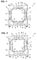
- a suspension assembly 10 is shown in Figures 1 and 2.
- the suspension assembly includes a first suspension member 12 that is preferably a generally quadrilateral longitudinal member such as an axle housing.
- the member 12 may include a pair of vertical and horizontal sides 14 with comers 16 interconnecting the sides 14.
- First 18 and second 20 seats are arranged opposite one another adjacent opposing sides 14.
- a fastener assembly 24 is used to clamp the seats 18 and 20 about the member 12 to secure a second suspension member 22 such as an attaching bracket for a suspension spring.
- the fastener assembly 24 may be a pair of bolts 26 and nuts 28 as shown in Figure 1 or a U-bolt 30 and nuts 28 as shown in Figure 2.
- prior art seat assemblies introduce compressive forces in only the vertical sides of the axle. As a result, the seats are more susceptible to becoming loose over time.
- some prior art devices have utilized a multi-piece seat assembly to introduce compressive forces in the horizontal sides in addition to the vertical sides.
- the seat assembly does not isolate the clamping force to the comers of the axle housing so that virtually all of the compressive force is concentrated in the vertical sides as is the prior art.
- the present invention seats 18 and 20 engage the comer 16 to introduce vertical V and horizontal H compressive forces in the sides 14 of the axle housing 12.
- the seats 18 and 20 include inwardly facing surfaces 32 with an intermediate surface 34 interconnecting the inwardly facing surfaces 32 to form a continuous unbroken surface 36. That is, the upper 18 and lower 20 seats each are a unitary structure that include a pair of inwardly facing surfaces 32 that face one another. The inwardly facing surfaces 32 engage the comers 16. For the embodiment shown in Figure 1, the comers may be defined by a flat, and the inwardly facing surfaces 32 may also be flat to better rotationally fix the seats 18 and 28 relative to the member 12.
- the intermediate surface 34 is spaced from the side 14.
- a more conventional axle housing 12 is shown in Figure 2.
- the comers of the housing 12 have radius comers 16.
- the inwardly facing surfaces 32 may be of an angle that is more resistant to permitting relative movement of the seats 18 and 20 relative to the member 12. It is to be understood, that the inwardly facing surfaces 32 and intermediate surface 34 may be of a shape other than those shown in Figures 1 and 2.
Landscapes
- Engineering & Computer Science (AREA)
- Mechanical Engineering (AREA)
- Vehicle Body Suspensions (AREA)
Applications Claiming Priority (2)
| Application Number | Priority Date | Filing Date | Title |
|---|---|---|---|
| US139989 | 1987-12-31 | ||
| US10/139,989 US6857645B2 (en) | 2002-05-07 | 2002-05-07 | Suspension seat and axle coupling |
Publications (2)
| Publication Number | Publication Date |
|---|---|
| EP1361085A2 true EP1361085A2 (de) | 2003-11-12 |
| EP1361085A3 EP1361085A3 (de) | 2004-10-27 |
Family
ID=29249777
Family Applications (1)
| Application Number | Title | Priority Date | Filing Date |
|---|---|---|---|
| EP03252817A Withdrawn EP1361085A3 (de) | 2002-05-07 | 2003-05-06 | Spannvorrichtung für eine Fahrzeugaufhängung |
Country Status (4)
| Country | Link |
|---|---|
| US (2) | US6857645B2 (de) |
| EP (1) | EP1361085A3 (de) |
| JP (1) | JP2004161239A (de) |
| CN (1) | CN1472086A (de) |
Cited By (5)
| Publication number | Priority date | Publication date | Assignee | Title |
|---|---|---|---|---|
| NL1032409C2 (nl) * | 2006-09-01 | 2008-03-04 | Weweler Nv | Verbindingsconstructie voor een wielas. |
| EP2081783A4 (de) * | 2006-10-31 | 2010-01-20 | Volvo Lastvagnar Ab | Achsaufhängungsanordnung für schwerfahrzeug |
| EP2253490A1 (de) * | 2009-05-20 | 2010-11-24 | Hendrickson International Corporation | Fahrzeugaufhängungsmittel |
| NL2010460C2 (en) * | 2013-03-15 | 2014-09-16 | Vdl Weweler B V | Wheel axle suspension with rectangular axle body. |
| WO2014142657A3 (en) * | 2013-03-15 | 2014-12-24 | Vdl Weweler B.V. | Wheel axle suspension with rectangular axle body |
Families Citing this family (10)
| Publication number | Priority date | Publication date | Assignee | Title |
|---|---|---|---|---|
| US20050253351A1 (en) * | 2004-05-14 | 2005-11-17 | Jaw-Ping Pan | Preloaded suspension bracket assembly for axle housing |
| US7416200B2 (en) * | 2005-05-13 | 2008-08-26 | Saf-Holland, Inc. | Vehicle suspension assembly |
| US20070290478A1 (en) * | 2006-06-15 | 2007-12-20 | Chien-Sheng Ting | Bicycle |
| CN101574914B (zh) * | 2009-06-16 | 2011-02-16 | 广东富华工程机械制造有限公司 | 半挂车车轴与悬挂的联结结构 |
| CN102267113B (zh) * | 2011-07-26 | 2013-05-08 | 重庆长安汽车股份有限公司 | 一种用于焊接悬置夹具的辅助工装 |
| US8955860B2 (en) | 2012-03-28 | 2015-02-17 | Saf-Holland, Inc. | Vehicle suspension assembly with integrated torque member and trailing arm mount |
| WO2016022127A1 (en) * | 2014-08-07 | 2016-02-11 | Watson & Chalin Manufacturing, Inc. | Suspension system with axle clamp that accomodates axle variations |
| CN106166921B (zh) * | 2016-08-11 | 2018-08-28 | 合肥超科电子有限公司 | 电动钢轨探伤车的从动桥及电动钢轨探伤车车架 |
| DE102017115692A1 (de) * | 2017-07-12 | 2019-01-17 | Bpw Bergische Achsen Kg | Achslenker sowie Achsaufhängung für eine Fahrzeugachse |
| US11110765B2 (en) | 2019-05-31 | 2021-09-07 | Mahindra N.A. Tech Center | Suspension spring saddle |
Family Cites Families (23)
| Publication number | Priority date | Publication date | Assignee | Title |
|---|---|---|---|---|
| US1314817A (en) * | 1919-09-02 | Fastening means for leaf-springs | ||
| US1539070A (en) * | 1919-04-30 | 1925-05-26 | Eaton Axle & Spring Co | Spring |
| US3386724A (en) * | 1965-11-04 | 1968-06-04 | Fruehauf Corp | Vehicle construction spring-to-axle mounting |
| US3547215A (en) * | 1968-06-07 | 1970-12-15 | Neway Equipment Co | Automotive vehicle suspension structure |
| US3630541A (en) * | 1970-06-11 | 1971-12-28 | Int Harvester Co | Vehicle axle suspension |
| US3785673A (en) * | 1971-09-20 | 1974-01-15 | Western Unit Corp | Preloaded spring beam and method employed alone or in combination with air bellows spring |
| US3913937A (en) * | 1974-07-03 | 1975-10-21 | Dura Corp | Universal axle pad and clamp assemblies for vehicle suspensions |
| US4033606A (en) * | 1975-08-06 | 1977-07-05 | Reyco Industries, Inc. | Vehicle tandem suspensions |
| US4465298A (en) * | 1982-01-21 | 1984-08-14 | Raidel Sr John E | U-Joint mount and lateral guide for air spring suspension |
| US4541653A (en) * | 1982-09-30 | 1985-09-17 | Raidel John E | Air spring suspension with angular torque beam, U-joint mount therefor, and lateral guides |
| US4693486A (en) * | 1986-04-09 | 1987-09-15 | Lear Siegler, Inc. | Trailing arm suspension with wrapper compression axle mounting |
| US4705294A (en) * | 1986-07-03 | 1987-11-10 | Raidel John E | Air suspension assembly with universal pivoted hanger bearings and rigid mount angular torque spring-beam |
| US4858949A (en) * | 1987-11-20 | 1989-08-22 | Lear Siegler Neway Corp. | Lightweight trailing arm suspension |
| US5078420A (en) * | 1990-11-14 | 1992-01-07 | The Boler Company | Tandem wheel and axle suspension |
| US5328159A (en) * | 1992-08-18 | 1994-07-12 | Dana Corporation | Axle housing attachment assembly |
| US6241266B1 (en) * | 1995-08-03 | 2001-06-05 | Holland Neway International, Inc. | Trailing arm suspension with wrapper compression axle mounting and articulated axle mounting |
| NL1003214C2 (nl) * | 1996-05-28 | 1997-12-03 | Weweler Nv | Asconstructie voor een voertuig, alsmede aspad en klemplaat daarvoor. |
| US6032967A (en) * | 1998-02-18 | 2000-03-07 | Dana Canada, Inc. | Axle and suspension connection assembly and method |
| US6015158A (en) * | 1998-06-24 | 2000-01-18 | Timbren Industries Inc. | Heavy duty truck suspension |
| DE19841746A1 (de) * | 1998-09-12 | 2000-03-16 | Claas Selbstfahr Erntemasch | Selbstfahrende landwirtschaftliche Arbeitsmaschine |
| US6264231B1 (en) * | 2000-03-20 | 2001-07-24 | The Boler Company | Axle suspension connection |
| DE10054839A1 (de) * | 2000-11-04 | 2002-05-08 | Daimler Chrysler Ag | Befestigung einer Fahrzeugachse an einer Achsaufhängung |
| DE10118696A1 (de) * | 2001-04-14 | 2002-10-24 | Bpw Bergische Achsen Kg | Achseinbindung für gefederte Fahrzeugachsen |
-
2002
- 2002-05-07 US US10/139,989 patent/US6857645B2/en not_active Expired - Lifetime
-
2003
- 2003-04-25 CN CNA031224695A patent/CN1472086A/zh active Pending
- 2003-05-06 EP EP03252817A patent/EP1361085A3/de not_active Withdrawn
- 2003-05-06 JP JP2003127788A patent/JP2004161239A/ja not_active Withdrawn
-
2005
- 2005-02-21 US US11/061,830 patent/US20050146107A1/en not_active Abandoned
Cited By (7)
| Publication number | Priority date | Publication date | Assignee | Title |
|---|---|---|---|---|
| NL1032409C2 (nl) * | 2006-09-01 | 2008-03-04 | Weweler Nv | Verbindingsconstructie voor een wielas. |
| EP1894754A1 (de) * | 2006-09-01 | 2008-03-05 | Weweler Nederland N.V. | Verbindungsstruktur für eine Radachse |
| EP2081783A4 (de) * | 2006-10-31 | 2010-01-20 | Volvo Lastvagnar Ab | Achsaufhängungsanordnung für schwerfahrzeug |
| EP2253490A1 (de) * | 2009-05-20 | 2010-11-24 | Hendrickson International Corporation | Fahrzeugaufhängungsmittel |
| NL2010460C2 (en) * | 2013-03-15 | 2014-09-16 | Vdl Weweler B V | Wheel axle suspension with rectangular axle body. |
| WO2014142657A3 (en) * | 2013-03-15 | 2014-12-24 | Vdl Weweler B.V. | Wheel axle suspension with rectangular axle body |
| US9669673B2 (en) | 2013-03-15 | 2017-06-06 | Vdl Weweler B.V. | Wheel axle suspension with rectangular axle body |
Also Published As
| Publication number | Publication date |
|---|---|
| JP2004161239A (ja) | 2004-06-10 |
| CN1472086A (zh) | 2004-02-04 |
| US20050146107A1 (en) | 2005-07-07 |
| EP1361085A3 (de) | 2004-10-27 |
| US6857645B2 (en) | 2005-02-22 |
| US20030209871A1 (en) | 2003-11-13 |
Similar Documents
| Publication | Publication Date | Title |
|---|---|---|
| EP1361085A2 (de) | Spannvorrichtung für eine Fahrzeugaufhängung | |
| CN1147409C (zh) | 增强的车辆框架结构 | |
| US20050253351A1 (en) | Preloaded suspension bracket assembly for axle housing | |
| US20100044991A1 (en) | Tubular axle beam suspension mount | |
| US20120056448A1 (en) | Vehicle body structure | |
| US6702309B2 (en) | Rear suspension for vehicles | |
| EP2234866B1 (de) | Befestigungsanordnung | |
| US6941634B2 (en) | Method for attaching axles to a leaf springs on hydraulic disc brake vehicles | |
| US11767067B2 (en) | Joint for mounting an elongate element to a structural element in a vehicle | |
| US20060181047A1 (en) | Trailing arm for a vehicle suspension | |
| AU5189201A (en) | Trailer suspension | |
| US10703157B2 (en) | Squeeze-welded spring seat | |
| JP3181792B2 (ja) | 自動車車体のサイドフレームとクロスメンバとの結合部構造 | |
| JP3245155U (ja) | ヒッチメンバー | |
| JP3132697B2 (ja) | グリルガードの取付構造 | |
| JPH11245640A (ja) | ストラットの車輪側取付部構造 | |
| JP2005313834A (ja) | サスペンションクロスメンバ | |
| JP3642350B2 (ja) | 防振装置 | |
| JPS6345538Y2 (de) | ||
| JP4905102B2 (ja) | 車両のスペアタイヤハンガー | |
| JP2003182678A (ja) | 自動2輪車の車体フレーム | |
| JP3440805B2 (ja) | 車両用ステアリングコラム支持部材の剛性強化構造 | |
| US20080309044A1 (en) | Vehicle suspension arm fitting structure | |
| JP2870319B2 (ja) | フォークリフトトラックのカウンタウエイト取付機構 | |
| JPH07215072A (ja) | ラジエータの支持構造 |
Legal Events
| Date | Code | Title | Description |
|---|---|---|---|
| PUAI | Public reference made under article 153(3) epc to a published international application that has entered the european phase |
Free format text: ORIGINAL CODE: 0009012 |
|
| AK | Designated contracting states |
Kind code of ref document: A2 Designated state(s): AT BE BG CH CY CZ DE DK EE ES FI FR GB GR HU IE IT LI LU MC NL PT RO SE SI SK TR |
|
| AX | Request for extension of the european patent |
Extension state: AL LT LV MK |
|
| PUAL | Search report despatched |
Free format text: ORIGINAL CODE: 0009013 |
|
| AK | Designated contracting states |
Kind code of ref document: A3 Designated state(s): AT BE BG CH CY CZ DE DK EE ES FI FR GB GR HU IE IT LI LU MC NL PT RO SE SI SK TR |
|
| AX | Request for extension of the european patent |
Extension state: AL LT LV MK |
|
| 17P | Request for examination filed |
Effective date: 20050404 |
|
| AKX | Designation fees paid |
Designated state(s): DE FR SE |
|
| STAA | Information on the status of an ep patent application or granted ep patent |
Free format text: STATUS: THE APPLICATION HAS BEEN WITHDRAWN |
|
| 18W | Application withdrawn |
Effective date: 20060209 |