EP1361363B1 - Spiralverdichter mit Schutz gegen Vakuum - Google Patents
Spiralverdichter mit Schutz gegen Vakuum Download PDFInfo
- Publication number
- EP1361363B1 EP1361363B1 EP03009421A EP03009421A EP1361363B1 EP 1361363 B1 EP1361363 B1 EP 1361363B1 EP 03009421 A EP03009421 A EP 03009421A EP 03009421 A EP03009421 A EP 03009421A EP 1361363 B1 EP1361363 B1 EP 1361363B1
- Authority
- EP
- European Patent Office
- Prior art keywords
- pressure hole
- open
- chamber
- suction
- shut member
- Prior art date
- Legal status (The legal status is an assumption and is not a legal conclusion. Google has not performed a legal analysis and makes no representation as to the accuracy of the status listed.)
- Expired - Lifetime
Links
Images



Classifications
-
- F—MECHANICAL ENGINEERING; LIGHTING; HEATING; WEAPONS; BLASTING
- F04—POSITIVE - DISPLACEMENT MACHINES FOR LIQUIDS; PUMPS FOR LIQUIDS OR ELASTIC FLUIDS
- F04C—ROTARY-PISTON, OR OSCILLATING-PISTON, POSITIVE-DISPLACEMENT MACHINES FOR LIQUIDS; ROTARY-PISTON, OR OSCILLATING-PISTON, POSITIVE-DISPLACEMENT PUMPS
- F04C28/00—Control of, monitoring of, or safety arrangements for, pumps or pumping installations specially adapted for elastic fluids
- F04C28/24—Control of, monitoring of, or safety arrangements for, pumps or pumping installations specially adapted for elastic fluids characterised by using valves controlling pressure or flow rate, e.g. discharge valves or unloading valves
- F04C28/26—Control of, monitoring of, or safety arrangements for, pumps or pumping installations specially adapted for elastic fluids characterised by using valves controlling pressure or flow rate, e.g. discharge valves or unloading valves using bypass channels
-
- F—MECHANICAL ENGINEERING; LIGHTING; HEATING; WEAPONS; BLASTING
- F04—POSITIVE - DISPLACEMENT MACHINES FOR LIQUIDS; PUMPS FOR LIQUIDS OR ELASTIC FLUIDS
- F04C—ROTARY-PISTON, OR OSCILLATING-PISTON, POSITIVE-DISPLACEMENT MACHINES FOR LIQUIDS; ROTARY-PISTON, OR OSCILLATING-PISTON, POSITIVE-DISPLACEMENT PUMPS
- F04C18/00—Rotary-piston pumps specially adapted for elastic fluids
- F04C18/02—Rotary-piston pumps specially adapted for elastic fluids of arcuate-engagement type, i.e. with circular translatory movement of co-operating members, each member having the same number of teeth or tooth-equivalents
-
- F—MECHANICAL ENGINEERING; LIGHTING; HEATING; WEAPONS; BLASTING
- F04—POSITIVE - DISPLACEMENT MACHINES FOR LIQUIDS; PUMPS FOR LIQUIDS OR ELASTIC FLUIDS
- F04C—ROTARY-PISTON, OR OSCILLATING-PISTON, POSITIVE-DISPLACEMENT MACHINES FOR LIQUIDS; ROTARY-PISTON, OR OSCILLATING-PISTON, POSITIVE-DISPLACEMENT PUMPS
- F04C18/00—Rotary-piston pumps specially adapted for elastic fluids
- F04C18/02—Rotary-piston pumps specially adapted for elastic fluids of arcuate-engagement type, i.e. with circular translatory movement of co-operating members, each member having the same number of teeth or tooth-equivalents
- F04C18/0207—Rotary-piston pumps specially adapted for elastic fluids of arcuate-engagement type, i.e. with circular translatory movement of co-operating members, each member having the same number of teeth or tooth-equivalents both members having co-operating elements in spiral form
- F04C18/0215—Rotary-piston pumps specially adapted for elastic fluids of arcuate-engagement type, i.e. with circular translatory movement of co-operating members, each member having the same number of teeth or tooth-equivalents both members having co-operating elements in spiral form where only one member is moving
-
- F—MECHANICAL ENGINEERING; LIGHTING; HEATING; WEAPONS; BLASTING
- F04—POSITIVE - DISPLACEMENT MACHINES FOR LIQUIDS; PUMPS FOR LIQUIDS OR ELASTIC FLUIDS
- F04C—ROTARY-PISTON, OR OSCILLATING-PISTON, POSITIVE-DISPLACEMENT MACHINES FOR LIQUIDS; ROTARY-PISTON, OR OSCILLATING-PISTON, POSITIVE-DISPLACEMENT PUMPS
- F04C28/00—Control of, monitoring of, or safety arrangements for, pumps or pumping installations specially adapted for elastic fluids
- F04C28/28—Safety arrangements; Monitoring
-
- F—MECHANICAL ENGINEERING; LIGHTING; HEATING; WEAPONS; BLASTING
- F04—POSITIVE - DISPLACEMENT MACHINES FOR LIQUIDS; PUMPS FOR LIQUIDS OR ELASTIC FLUIDS
- F04C—ROTARY-PISTON, OR OSCILLATING-PISTON, POSITIVE-DISPLACEMENT MACHINES FOR LIQUIDS; ROTARY-PISTON, OR OSCILLATING-PISTON, POSITIVE-DISPLACEMENT PUMPS
- F04C2270/00—Control; Monitoring or safety arrangements
- F04C2270/70—Safety, emergency conditions or requirements
- F04C2270/72—Safety, emergency conditions or requirements preventing reverse rotation
-
- F—MECHANICAL ENGINEERING; LIGHTING; HEATING; WEAPONS; BLASTING
- F04—POSITIVE - DISPLACEMENT MACHINES FOR LIQUIDS; PUMPS FOR LIQUIDS OR ELASTIC FLUIDS
- F04C—ROTARY-PISTON, OR OSCILLATING-PISTON, POSITIVE-DISPLACEMENT MACHINES FOR LIQUIDS; ROTARY-PISTON, OR OSCILLATING-PISTON, POSITIVE-DISPLACEMENT PUMPS
- F04C23/00—Combinations of two or more pumps, each being of rotary-piston or oscillating-piston type, specially adapted for elastic fluids; Pumping installations specially adapted for elastic fluids; Multi-stage pumps specially adapted for elastic fluids
- F04C23/008—Hermetic pumps
Definitions
- the present invention relates to a vacuum preventing device of a scroll compressor comprising a chamber formed at one side of a fixed scroll of the scroll compressor, the chamber communicating with a suction pressure zone through a suction pressure hole, a discharge pressure zone through a discharge pressure hole and a middle pressure zone through a middle pressure hole, wherein the middle pressure hole and the discharge pressure hole are formed on opposite sides of the chamber, an open and shut member installed inside the chamber and selectively allowing the discharge pressure hole and the suction pressure hole to communicate with each other in such a way that in case the gas pressure of the middle pressure zone is higher than the gas pressure of the discharge zone the open and shut member is forced into a first position in which communication between the discharge pressure hole and the suction pressure hole is prevented and in case the gas pressure of the middle pressure zone is lower than the gas pressure of the discharge zone the open and shut member is forced into a second position in which communication between the discharge pressure hole and the suction pressure hole is allowed, a spring installed inside the chamber providing an elastic force to the open and shut member.
- a compressor changing a mechanical energy to a latent energy of a compressive fluid, is divided into a reciprocating type, a scroll type, a centrifugal type and a vane type.
- the scroll type compressor has a structure of sucking, compressing and discharging gas by using a rotor like the centrifugal type compressor or the vane type compressor, unlike the reciprocating type compressor which uses a linear reciprocal movement of a piston.
- Figure 1 is a vertical-sectional view showing inside of a conventional scroll compressor.
- the conventional scroll compressor includes a case 1 having a gas suction tube (SP) and a gas discharge tube (DP), a main frame 2 and a sub-frame (not shown) installed, respectively, at both upper and lower sides of the inner circumferential surface of the case 1, a rotational shaft 4 coupled at a central portion of a drive motor 3 so as to transmit a rotational force of the drive motor 3, an orbiting scroll 5 installed eccentrically rotatable at an upper portion of the rotational shaft 4 and having an involute curve shaped wrap 5a at an upper portion thereof, and a fixed scroll 6 having an involute curve shaped wrap 6a so as to form a plurality of compression spaces (P) by being coupled with the orbiting scroll 5.
- SP gas suction tube
- DP gas discharge tube
- main frame 2 and a sub-frame (not shown) installed, respectively, at both upper and lower sides of the inner circumferential surface of the case 1
- a rotational shaft 4 coupled at a central portion of a drive motor 3 so as to transmit a rotational
- the case 1 is internally divided into a suction pressure zone (S1) and a discharge pressure zone (S2) by means of a high low pressure separation plate 7, and a middle pressure zone (S3) is formed communicating with the compression space (P).
- a gas suction hole 6b and a gas discharge hole 6c are formed at the side and at the central portion of the fixed scroll 6, and a non-return valve 8 is installed at an upper surface of the fixed scroll 6 to prevent discharged gas from flowing backward.
- the main frame 2 and the sub-frame are fixed at the inner circumferential surface of the case 1 by a typical fixing method such as welding, and the fixed scroll 6 is fixed at the lower surface of the high and low pressure separation plate 7 by means of a typical fixing unit such as a bolt.
- a vacuum preventing device 20 is provided in the conventional art.
- Figure 2 is a vertical-sectional view showing an operation of the vacuum preventing device when the conventional scroll compressor is normally operated
- Figure 3 is a vertical-sectional view showing an operation of the vacuum preventing device when the conventional scroll compressor is not normally operated
- Figure 4 is a sectional view taken along line A-A of Figure 2 .
- the vacuum preventing device 20 is constructed such that a chamber 10 is formed at one side of the fixed scroll 6 and a discharge pressure hole 11 is formed at an upper surface of the chamber 10, communicating with the discharge pressure zone (S2).
- a middle pressure hole 12 is formed at a lower surface of the chamber 10, communicating with the middle pressure zone (S3).
- a plug 14 having a suction pressure hole 13 is fixed by a fixing pin 15 at the side of an opening portion of the chamber 10. The suction pressure hole 13 communicates with the discharge pressure hole 11.
- An open and shut member 17 is movably installed inside the chamber 10 to selectively communicate the discharge pressure hole 11 and the suction pressure hole 13.
- a spring 16 is installed at the side of the opening portion of the chamber 10 to limit movement of the open and shut member 17 and provide an elastic force to the open and shut member 17.
- the drive motor 3 rotates the rotational shaft 4, and at this time, the orbiting scroll 5 coupled to the rotational shaft 4 is orbited as long as the eccentric distance.
- the plurality of compression spaces (P) formed between the wrap 5a of the orbiting scroll 5 and the wrap 6a of the fixed scroll 6 are reduced in their volume as the orbiting scroll 5 is gradually moved toward the center of the fixed scroll 6 according to its continuous orbiting movement.
- the gas at the suction pressure zone (S2) is sucked into the compression spaces (P) through the suction hole 6b, and the sucked gas is discharged to the discharge pressure zone (S2) through the discharge hole 6c.
- the open and shut member 17 overcomes the elastic force of the spring 16 and close (seal) the discharge pressure hole 11. Conversely, if the compressor is not morally operated, since the middle pressure is weaker than the elastic force of the spring 16, the open and shut member 17 submits to the elastic force of the spring and opens the discharge pressure hole 11. At this time, the discharge pressure hole 11 communicates with the suction pressure hole 13.
- Document WO 00/73659 A1 discloses a vacuum preventing device of a scroll compressor comprising a chamber formed at one side of a fixed scroll and having a suction pressure hole, a middle pressure hole and a discharge pressure hole communicating with a suction pressure zone, a middle pressure zone and a discharge pressure zone, respectively. Furthermore, an open and shut member is installed inside the chamber and allows the discharge pressure hole and the suction pressure hole to communicate with each other by virtue of a gas pressure of the middle pressure zone and an elastic force of a spring. Finally, the lower part of the open and shut member may be defined as a plane "compression gas receiving part", that is a part formed at the lower surface of the open and shut member and facing the middle pressure hole in order to come into contact with the compression gas of the middle pressure zone.
- the clearance is formed on one hand with such a minimum size as to allow the open and shut member to easily move slidably inside the chamber, but on the other hand so fine as to not allow a gas to be leaked through the discharge pressure hole when the open and shut member closes the discharge pressure hole.
- a vacuum preventing device of the type described before wherein a concave compression gas reception portion in the form of a recess is formed at the side of the open and shut member facing the middle pressure hole, wherein the concave compression gas reception portion is opened toward the middle pressure hole in order to receive portion of the compression gas of the middle pressure zone, wherein the concave compression gas reception portion is shaped, dimensioned and located so as to overcome the load of the spring when the compressor is operated normally, and wherein the shut member slides in a direction that is parallel to the sides of the chamber that define the middle pressure hole and the discharge pressure hole.
- Figure 5 is a vertical-sectional view showing a portion of a scroll compressor in accordance with a first embodiment of the present invention
- Figure 6 is an exploded perspective view showing a vacuum preventing device of the scroll compressor of Figure 5
- Figure 7 is a vertical-sectional view showing the operation of the vacuum preventing device when a compressor is normally operated
- Figure 8 is a vertical-sectional view showing an operation of the vacuum preventing device when the compressor is not normally operated.
- the scroll compressor includes a case 1 divided into a suction pressure zone (S1) for sucking a gas and a discharge pressure zone (S2) for discharging a gas; a fixed scroll 6 fixedly installed inside the case 1; an orbiting scroll 5 coupled to the fixed scroll 6 to form a compression space (P) communicating with an internal middle pressure zone (S3) and coupled to be movable eccentrically in an orbiting manner to the rotational shaft 4 of the drive motor 3 inside the case 1 so as to suck, compress and discharge a gas; and a vacuum preventing unit 100 installed at one side of the fixed scroll 6.
- the case 1 is divided into the suction pressure zone (S1) and the discharge pressure zone (S2) by a high and low pressure separation plate 7, and a gas suction tube (SP) (refer to Figure 1 ) is formed at the side of the suction pressure zone (S1) of the case 1 and a gas discharge tube (DP) is formed at the side of the discharge pressure zone (S2) of the case 1.
- SP gas suction tube
- DP gas discharge tube
- the orbiting scroll 5 installed eccentrically rotatable at an upper end of the rotational shaft 4 has an involute curve shaped wrap 5a at its upper portion, and the fixed scroll 6 coupled to the orbiting scroll 5 includes an involute curve shaped wrap 6a at its lower portion.
- a gas suction hole 6b and a gas discharge hole 6c are formed at the side and at the central portion of the fixed scroll 6, and a non-return open and shut member (refer to Figure 1 ) is installed at an upper surface of the fixed scroll 6 to prevent discharged gas from flowing backward.
- the suction pressure zone (S1) of the compressor is in a high vacuum state, and at this time, parts of the compressor can be damaged.
- the vacuum preventing device 100 is installed at the fixed scroll 6.
- the vacuum preventing device 100 is constructed such that a chamber 10 is formed at one side of the fixed scroll 6 and a discharge pressure hole 11 is formed communicating with the discharge pressure zone (S2) is formed at an upper surface of the chamber 10.
- a middle pressure hole 12 communicating with the middle pressure zone (S3) is formed at a lower surface of the chamber 10, a plug 14 having a suction pressure hole 13 is fixed by a fixing pin 15 at the side of an opening portion of the chamber 10.
- the suction pressure hole 13 communicates with the discharge pressure hole 11.
- An open and shut member 17 is movably installed inside the chamber 10 to selectively communicate the discharge pressure hole 11 and the suction pressure hole 13.
- a spring 16 is installed at the side of the opening portion of the chamber 10 to limit movement of the open and shut member 17 and provide an elastic force to the open and shut member 17.
- a concave compression gas reception portion 111 is formed at a lower surface of the open and shut member 110, and the compression gas reception portion 111 is opened inwardly of the chamber 10 (that is, toward the center of the fixed scroll.
- the compression gas reception portion 111 As for the compression gas reception portion 111, it is formed inclined toward the middle pressure zone (S3) on the basis of a vertical central line (L) of the open and shut member 110 and adjacent to the inner wall of the chamber 10 to form a closed space there.
- a gas pressurizing area of the compression gas reception portion 111 is preferably formed wider than that of the middle pressure hole 12.
- a suction gas reception portion 112 is formed at an upper surface of the open and shut member 110.
- a pressurizing area of the suction has reception portion 112 is preferably formed smaller than that of the compression gas reception portion 111.
- suction gas reception portion 112 it is formed inclined toward the suction pressure zone (S1) on the basis of the vertical central line (L) of the open and shut member 110 and opened outwardly of the chamber 10 (that is, toward the outer circumference of the fixed scroll).
- a portion 112a except for the suction gas reception portion 112 of the entire upper surface of the open and shut member 110 closes the discharge pressure hole 11.
- the discharge pressure hole 11 is positioned at the right center of the portion 112a.
- the discharge pressure hole 113 is not positioned at the right center of the portion 112a, the discharge pressure is concentrated to only one side of the portion 112a, degrading the closing efficiency.
- the chamber 10 and the open and shut member 110 is preferably formed in a non-circle shape or in a rectangular form when vertically projected.
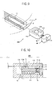
- Figure 9 is an exploded perspective view of a scroll compressor in accordance with a second embodiment of the present invention
- Figure 10 is a vertical-sectional view showing an operation of a vacuum preventing device when the compressor of Figure 9 is normally operated.
- a vacuum preventing device 200 in accordance with the second embodiment of the present invention is constructed such that a tilting moment preventing protrusion 112b is formed at the bottom of the suction gas reception portion 112 and a discharge pressure hole 11 is positioned at the right center of the upper surface of the tilting moment preventing protrusion 112b when the compressor is normally operated.
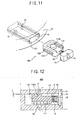
- Figure 11 is an exploded perspective view showing a vacuum preventing device of a scroll compressor in accordance with a third embodiment of the present invention.
- a vacuum preventing device 300 in accordance with the third embodiment of the present invention includes a guide groove 121 and a guide rail 120 which are generally used at an inner wall of the chamber 10 and an outer surface of the open and shut member 110, respectively, in order to prevent a smooth sliding movement of the open and shut member 110 and the tilting moment.
- the guide rail 120 can be installed at the inner wall of the chamber 10 and the guide groove 121 can be installed at the outer surface of the open and shut member 110.
- Figure 12 is a vertical-sectional view showing a vacuum preventing device 400 of a scroll compressor in accordance with a fourth embodiment of the present invention.
- a vacuum preventing device in accordance with the fourth embodiment of the present invention is constructed such that the middle pressure hole 12 and the discharge pressure hole 11 are positioned on the same vertical line to make each resultant force to work on the same vertical central line, thereby preventing the tilting moment of the open and shut member.
- Figure 13 is an exploded perspective view showing a vacuum preventing device of a scroll compressor in accordance with a fifth embodiment of the present invention
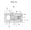
- Figure 14 is a vertical-sectional view showing the vacuum preventing device of a scroll compressor in accordance with the fifth embodiment of the present invention.
- a vacuum preventing device 500 in accordance with the fifth embodiment of the present invention includes: a chamber 510 formed at an upper surface of the fixed scroll 6 and having a suction pressure hole 13 communicating with the suction pressure zone (S1) formed at one side and a middle pressure hole 12 communicating with the middle pressure zone (S3) formed at the other side; a cover member 530 coupled at an upper surface of the fixed scroll 6 to cover the chamber 510 and having a discharge pressure hole 11 communicating with the discharge pressure zone (S2) formed at the center thereof; an open and shut member 520 installed to be movable elastically by virtue of the spring 16 in the chamber 510 in order to selectively allow the discharge pressure hole 11 and the suction pressure hole 13 to communicate with each other; and a compression gas receiving part 521 formed at a lower surface of the open and shut member 520 facing the middle pressure hole 12.
- a suction gas receiving part 522 is formed at an upper surface of the open and shut member 520 facing the discharge pressure hole 11.
- the compression gas receiving part 521 are formed to be recess.
- the compressor is operated that as the orbiting scroll 5 orbits by virtue of the drive motor 3, it sucks the gas of the suction pressure zone (S1) into the compression spaces (P), compresses it in the compression spaces (P) and discharges it to the discharge pressure zone (S2).
- the vacuum preventing device 100 is operated that when the compressor is normally operated, since the pressure of the middle pressure zone (S3) is stronger than the elastic force of the spring 16, the open and shut member 110 overcomes the elastic force of the spring 16 and closes the discharge pressure hole 11.
- the discharge side pressure is applied to the portion adjacent to the discharge pressure hole 11 as well as to the discharge pressure hole 11.
- the suction side pressure is applied into the suction gas reception portion 111, and accordingly, the discharge side pressure is partially offset as much owing to the suction side pressure.
- the pressure of the compression gas collected to the compression gas reception portion 111 pressurizes the open and shut member 110 upwardly.
- the middle pressure is stronger than the discharge pressure, so that the open and shut member 110 can tightly close the discharge pressure hole 11 without a gas leakage.
- the scroll compressor and the vacuum preventing device of the scroll compressor of the present invention have the following advantages.
- the clearance between the chamber and the open and shut member is minimized by using the pressure of the middle pressure zone, so that when the compressor is normally operated, a gas leakage can be effectively prevented from the clearance.
- the compression efficiency of the compressor can be heightened.
- the tolerance limit range in designing and fabrication of the clearance is widened, the fabrication cost can be considerably reduced and its productivity can be improved.
Landscapes
- Engineering & Computer Science (AREA)
- Mechanical Engineering (AREA)
- General Engineering & Computer Science (AREA)
- Physics & Mathematics (AREA)
- Fluid Mechanics (AREA)
- Applications Or Details Of Rotary Compressors (AREA)
- Rotary Pumps (AREA)
Claims (12)
- Vorrichtung zum Verhindern eines Vakuums (100) für einen Spiralverdichter, enthaltend:eine Kammer (10, 510), die auf einer Seite einer feststehenden Schnecke (6) des Spiralverdichters gebildet ist, welche Kammer (10, 510) mit einer Ansaugdruckzone (S1) durch ein Ansaugdruckloch (13), einer Abgabedruckzone (S2) durch ein Abgabedruckloch (11) und einer Mitteldruckzone (S3) durch ein Mitteldruckloch (12) kommuniziert, wobei das Mitteldruckloch (12) und das Abgabedruckloch (11) an entgegengesetzten Seiten der Kammer (10, 510) gebildet sind;ein Öffnungs- und Verschlusselement (110), das innerhalb der Kammer (10, 510) eingebaut ist und selektiv die Kommunikation des Abgabedrucklochs (11) und des Ansaugdrucklochs (13) miteinander in der Weise erlaubt, dass in dem Fall, dass der Gasdruck der Mitteldruckzone (S3) höher ist als der Gasdruck der Abgabezone (S2), das Öffnungs- und Verschlusselement (110) zwangsweise in eine erste Position gebracht wird, in der die Kommunikation zwischen dem Abgabedruckloch (11) und dem Ansaugdruckloch (13) verhindert wird, und in dem Fall, dass der Gasdruck der Mitteldruckzone (S3) niedriger ist als der Gasdruck der Abgabezone (S2), das Öffnungs- und Verschlusselement (110) zwangsweise in eine zweite Position gebracht wird, in der die Kommunikation zwischen dem Abgabedruckloch (11) und dem Ansaugdruckloch (13) zugelassen wird;eine innerhalb der Kammer (10, 510) eingebaute Feder (16), die eine elastische Kraft an das Öffnungs- und Verschlusselement (110) anlegt,dadurch gekennzeichnet, dass ein konkaver
Kompressionsgasaufnahmeabschnitt (111) in Form einer Vertiefung an der Seite des Öffnungs- und Verschlusselements (110) gebildet ist, die zu dem Mitteldruckloch (12) weist, wobei der konkave Kompressionsgasaufnahmeabschnitt (111) zu dem Mitteldruckloch (12) hin geöffnet ist, um einen Teil des Kompressionsgases der Mitteldruckzone (S3) aufzunehmen, wobei der konkave Kompressionsgasaufnahmeabschnitt (111) so geformt, dimensioniert und angeordnet ist, dass er die Last der Feder (16) überwindet, wenn der Kompressor normal arbeitet, und wobei das Verschlusselement (110) in eine Richtung gleitet, die parallel zu den Seiten der Kammer (10, 510) ist, die das Mitteldruckloch (12) und das Abgabedruckloch (11) begrenzen. - Vorrichtung nach Anspruch 1, wobei der Kompressionsgasaufnahmeabschnitt (111) in Bezug auf eine senkrechte Mittellinie (L) des Öffnungs- und Verschlusselements (110) in Richtung der Mitteldruckzone (S3) verschoben ist.
- Vorrichtung nach Anspruch 1, wobei die Ränder des Kompressionsgasaufnahmeabschnitts (111) mit der Innenfläche der Kammer (10, 510) zusammenwirken, so dass sie einen hermetischen Raum bilden, wenn das Öffnungs- und Verschlusselement (110) in der zweiten Position ist.
- Vorrichtung nach Anspruch 1, wobei ein konkaver Ansauggasaufnahmeabschnitt (112) auf der Seite des Öffnungs-und Verschlusselements (110) gebildet ist, die zu dem Abgabedruckloch (11) weist.
- Vorrichtung nach Anspruch 4, wobei der Gasdruckaufbauraum innerhalb des Ansauggasaufnahmeabschnitts (112) kleiner ist als der des Kompressionsgasaufnahmeabschnitts (111).
- Vorrichtung nach Anspruch 4, wobei der Ansauggasaufnahmeabschnitt (112) in Bezug auf die senkrechte Mittellinie (L) des Öffnungs- und Verschlusselements (110) in Richtung der Ansaugdruckzone (S1) verschoben ist.
- Vorrichtung nach Anspruch 4, wobei der Kompressionsgasaufnahmeabschnitt (111) und der Ansauggasaufnahmeabschnitt (112) in entgegengesetzte Richtungen geöffnet sind.
- Vorrichtung nach Anspruch 6, wobei ein Vorsprung (112b) am Boden des Ansauggasaufnahmeabschnitts (112) gebildet ist, der mit der Innenfläche der Kammer (10, 510) in Kontakt ist, um das Kippen des Öffnungs- und Verschlusselements (110) zu verhindern, wenn das Öffnungs- und Verschlusselement (110) in der ersten Position ist.
- Vorrichtung nach Anspruch 1, wobei eine Führungsschiene (120) entweder an der Innenwand der Kammer (10, 510) oder der Außenfläche des Öffnungs- und Verschlusselements (110) gebildet ist und eine Führungsnut (121) auf der entgegengesetzten Seite gebildet ist.
- Vorrichtung nach Anspruch 1, wobei das Mitteldruckloch (12) und das Abgabedruckloch (11) einander entgegengesetzt angeordnet sind.
- Vorrichtung nach Anspruch 1, wobei der Abschnitt der Kammer (10, 510) mit dem Abgabedruckloch (11), das mit der Abgabedruckzone (S2) kommuniziert, durch ein separates Abdeckelement (530) gebildet ist, das mit einer oberen Oberfläche der feststehenden Schnecke (6) gekoppelt ist, um die Kammer (10, 510) abzudecken.
- Vorrichtung nach Anspruch 11, wobei ein Bolzen (B) in das Abdeckelement (530) eingreift.
Applications Claiming Priority (2)
| Application Number | Priority Date | Filing Date | Title |
|---|---|---|---|
| KR2002024854 | 2002-05-06 | ||
| KR10-2002-0024854A KR100438621B1 (ko) | 2002-05-06 | 2002-05-06 | 스크롤 압축기의 고진공 방지 장치 |
Publications (3)
| Publication Number | Publication Date |
|---|---|
| EP1361363A2 EP1361363A2 (de) | 2003-11-12 |
| EP1361363A3 EP1361363A3 (de) | 2003-11-26 |
| EP1361363B1 true EP1361363B1 (de) | 2008-09-24 |
Family
ID=29244823
Family Applications (1)
| Application Number | Title | Priority Date | Filing Date |
|---|---|---|---|
| EP03009421A Expired - Lifetime EP1361363B1 (de) | 2002-05-06 | 2003-04-25 | Spiralverdichter mit Schutz gegen Vakuum |
Country Status (5)
| Country | Link |
|---|---|
| US (1) | US7018180B2 (de) |
| EP (1) | EP1361363B1 (de) |
| KR (1) | KR100438621B1 (de) |
| CN (1) | CN1267646C (de) |
| DE (1) | DE60323705D1 (de) |
Families Citing this family (39)
| Publication number | Priority date | Publication date | Assignee | Title |
|---|---|---|---|---|
| US6558126B1 (en) * | 2000-05-01 | 2003-05-06 | Scroll Technologies | Compressor utilizing low volt power tapped from high volt power |
| CN100412374C (zh) * | 2003-12-12 | 2008-08-20 | 乐金电子(天津)电器有限公司 | 涡旋式压缩机的真空防止装置 |
| KR100575709B1 (ko) * | 2004-11-12 | 2006-05-03 | 엘지전자 주식회사 | 스크롤 압축기 |
| CN1782415B (zh) * | 2004-11-30 | 2010-05-05 | 乐金电子(天津)电器有限公司 | 卷轴压缩机的高真空防止装置 |
| US7165954B2 (en) * | 2004-12-27 | 2007-01-23 | Lg Electronics Inc. | Apparatus for preventing vacuum state in scroll compressor |
| EP1917442B1 (de) * | 2006-03-31 | 2015-12-09 | LG Electronics Inc. | Vorrichtung zur verhinderung des entstehens eines vakuums in einem spiralverdichter |
| US8502952B2 (en) * | 2007-04-14 | 2013-08-06 | Industrial Technology Research Institute | Color cholesteric liquid crystal display devices and fabrication methods thereof |
| TWI368061B (en) * | 2007-08-16 | 2012-07-11 | Ind Tech Res Inst | Fabrication methods for liquid crystal display devices |
| US7988433B2 (en) | 2009-04-07 | 2011-08-02 | Emerson Climate Technologies, Inc. | Compressor having capacity modulation assembly |
| US8517703B2 (en) * | 2010-02-23 | 2013-08-27 | Emerson Climate Technologies, Inc. | Compressor including valve assembly |
| CN102650277B (zh) * | 2011-02-28 | 2016-11-16 | 浙江三花制冷集团有限公司 | 多级压缩机和泄压阀 |
| US9249802B2 (en) | 2012-11-15 | 2016-02-02 | Emerson Climate Technologies, Inc. | Compressor |
| US9651043B2 (en) | 2012-11-15 | 2017-05-16 | Emerson Climate Technologies, Inc. | Compressor valve system and assembly |
| US9435340B2 (en) | 2012-11-30 | 2016-09-06 | Emerson Climate Technologies, Inc. | Scroll compressor with variable volume ratio port in orbiting scroll |
| US9127677B2 (en) | 2012-11-30 | 2015-09-08 | Emerson Climate Technologies, Inc. | Compressor with capacity modulation and variable volume ratio |
| US9739277B2 (en) | 2014-05-15 | 2017-08-22 | Emerson Climate Technologies, Inc. | Capacity-modulated scroll compressor |
| US9989057B2 (en) | 2014-06-03 | 2018-06-05 | Emerson Climate Technologies, Inc. | Variable volume ratio scroll compressor |
| US9790940B2 (en) | 2015-03-19 | 2017-10-17 | Emerson Climate Technologies, Inc. | Variable volume ratio compressor |
| US10378540B2 (en) | 2015-07-01 | 2019-08-13 | Emerson Climate Technologies, Inc. | Compressor with thermally-responsive modulation system |
| CN207377799U (zh) | 2015-10-29 | 2018-05-18 | 艾默生环境优化技术有限公司 | 压缩机 |
| US10890186B2 (en) | 2016-09-08 | 2021-01-12 | Emerson Climate Technologies, Inc. | Compressor |
| US10801495B2 (en) | 2016-09-08 | 2020-10-13 | Emerson Climate Technologies, Inc. | Oil flow through the bearings of a scroll compressor |
| US10753352B2 (en) | 2017-02-07 | 2020-08-25 | Emerson Climate Technologies, Inc. | Compressor discharge valve assembly |
| US11022119B2 (en) | 2017-10-03 | 2021-06-01 | Emerson Climate Technologies, Inc. | Variable volume ratio compressor |
| US10962008B2 (en) | 2017-12-15 | 2021-03-30 | Emerson Climate Technologies, Inc. | Variable volume ratio compressor |
| US10885753B2 (en) | 2018-03-21 | 2021-01-05 | Fasteners For Retail, Inc. | Anti-theft device with remote alarm feature |
| US10993550B2 (en) | 2018-03-21 | 2021-05-04 | Fasteners For Retail, Inc. | Anti-theft retail merchandise pusher with remote alarm feature |
| US10995753B2 (en) | 2018-05-17 | 2021-05-04 | Emerson Climate Technologies, Inc. | Compressor having capacity modulation assembly |
| EP3945949B1 (de) | 2019-04-05 | 2025-01-22 | Fasteners for Retail, Inc. | Diebstahlsicherungsschieber mit inkrementeller abstandserfassung |
| US11154143B2 (en) | 2019-09-30 | 2021-10-26 | Fasteners For Retail, Inc. | Anti-theft hook with integrated loss prevention functionality |
| US11655813B2 (en) | 2021-07-29 | 2023-05-23 | Emerson Climate Technologies, Inc. | Compressor modulation system with multi-way valve |
| US12433428B2 (en) | 2021-08-23 | 2025-10-07 | Fasteners For Retail, Inc. | Anti-sweeping hook with integrated inventory monitoring and/or loss prevention functionality |
| US12437262B2 (en) | 2021-08-23 | 2025-10-07 | Fasteners For Retail, Inc. | Anti-sweeping hook with integrated inventory monitoring and/or loss prevention functionality |
| US12259163B2 (en) | 2022-06-01 | 2025-03-25 | Copeland Lp | Climate-control system with thermal storage |
| US11846287B1 (en) | 2022-08-11 | 2023-12-19 | Copeland Lp | Scroll compressor with center hub |
| US11965507B1 (en) | 2022-12-15 | 2024-04-23 | Copeland Lp | Compressor and valve assembly |
| US12416308B2 (en) | 2022-12-28 | 2025-09-16 | Copeland Lp | Compressor with shutdown assembly |
| US12173708B1 (en) | 2023-12-07 | 2024-12-24 | Copeland Lp | Heat pump systems with capacity modulation |
| US12163523B1 (en) | 2023-12-15 | 2024-12-10 | Copeland Lp | Compressor and valve assembly |
Family Cites Families (13)
| Publication number | Priority date | Publication date | Assignee | Title |
|---|---|---|---|---|
| JPS60182388A (ja) | 1984-02-29 | 1985-09-17 | Hitachi Ltd | スクロ−ル圧縮機 |
| JPS6111401A (ja) * | 1984-06-26 | 1986-01-18 | Mitsubishi Heavy Ind Ltd | 回転型流体機械 |
| JPS6153486A (ja) * | 1984-08-22 | 1986-03-17 | Hitachi Ltd | スクロ−ル圧縮機 |
| JP2545780B2 (ja) | 1985-09-19 | 1996-10-23 | 株式会社日本自動車部品総合研究所 | スクロ−ル型圧縮機 |
| JPH02230995A (ja) | 1989-03-02 | 1990-09-13 | Mitsubishi Heavy Ind Ltd | ヒートポンプ用圧縮機及びその運転方法 |
| JPH0367089A (ja) * | 1989-08-04 | 1991-03-22 | Matsushita Refrig Co Ltd | 回転式圧縮機に於ける吐出弁機構 |
| JP2846106B2 (ja) * | 1990-11-16 | 1999-01-13 | 三菱重工業株式会社 | スクロール型圧縮機 |
| JP2972370B2 (ja) * | 1991-03-15 | 1999-11-08 | サンデン株式会社 | 可変容量スクロール圧縮機 |
| US6095765A (en) * | 1998-03-05 | 2000-08-01 | Carrier Corporation | Combined pressure ratio and pressure differential relief valve |
| US6190138B1 (en) * | 1998-06-12 | 2001-02-20 | Scroll Technologies | Flow valve for correcting reverse rotation in scroll compressor |
| JP3726501B2 (ja) * | 1998-07-01 | 2005-12-14 | 株式会社デンソー | 可変容量式スクロール型圧縮機 |
| US6210120B1 (en) * | 1999-03-19 | 2001-04-03 | Scroll Technologies | Low charge protection vent |
| CN1302206C (zh) | 1999-06-01 | 2007-02-28 | Lg电子株式会社 | 防止涡旋压缩机产生真空的装置 |
-
2002
- 2002-05-06 KR KR10-2002-0024854A patent/KR100438621B1/ko not_active Expired - Fee Related
-
2003
- 2003-04-23 US US10/420,878 patent/US7018180B2/en not_active Expired - Fee Related
- 2003-04-25 DE DE60323705T patent/DE60323705D1/de not_active Expired - Lifetime
- 2003-04-25 EP EP03009421A patent/EP1361363B1/de not_active Expired - Lifetime
- 2003-05-06 CN CNB031409903A patent/CN1267646C/zh not_active Expired - Fee Related
Also Published As
| Publication number | Publication date |
|---|---|
| US7018180B2 (en) | 2006-03-28 |
| CN1267646C (zh) | 2006-08-02 |
| CN1456814A (zh) | 2003-11-19 |
| US20030206813A1 (en) | 2003-11-06 |
| KR20030086728A (ko) | 2003-11-12 |
| DE60323705D1 (de) | 2008-11-06 |
| EP1361363A2 (de) | 2003-11-12 |
| KR100438621B1 (ko) | 2004-07-02 |
| EP1361363A3 (de) | 2003-11-26 |
Similar Documents
| Publication | Publication Date | Title |
|---|---|---|
| EP1361363B1 (de) | Spiralverdichter mit Schutz gegen Vakuum | |
| US6863510B2 (en) | Vacuum preventing oil seal for scroll compressor | |
| US6769881B2 (en) | Vacuum preventing device for scroll compressor | |
| EP1917442B1 (de) | Vorrichtung zur verhinderung des entstehens eines vakuums in einem spiralverdichter | |
| US6893229B2 (en) | Vacuum preventing device of scroll compressor | |
| US7393190B2 (en) | Discharge valve system of scroll compressor | |
| EP3334936B1 (de) | Verdichter | |
| US7335004B2 (en) | Apparatus for varying capacity in scroll compressor | |
| JP2005508480A (ja) | 吐出バルブ及びこれを利用した圧縮機 | |
| JP2795614B2 (ja) | 往復動式圧縮機 | |
| KR100360861B1 (ko) | 스크롤 압축기의 진공압축 방지장치 | |
| US12215685B2 (en) | Scroll compressor | |
| KR100332801B1 (ko) | 스크롤 압축기의 진공압축 방지장치 | |
| KR100317379B1 (ko) | 스크롤 압축기의 진공압축 방지장치 | |
| US6748971B2 (en) | Discharge valve assembly of fluid machinery | |
| KR100317378B1 (ko) | 스크롤 압축기의 진공압축 방지장치 | |
| KR100343730B1 (ko) | 스크롤 압축기의 진공압축 방지장치 | |
| US7189067B2 (en) | Scroll compressor having vacuum preventing structure | |
| KR20010076882A (ko) | 스크롤 압축기의 진공압축 방지장치 | |
| KR100343731B1 (ko) | 스크롤 압축기의 진공압축 방지장치 | |
| KR100360857B1 (ko) | 스크롤 압축기의 진공압축 방지장치 | |
| KR100434401B1 (ko) | 스크롤 압축기의 진공압축 방지장치 | |
| KR100417419B1 (ko) | 스크롤 압축기의 역회전 방지장치 | |
| KR20060033268A (ko) | 스크롤 압축기의 바이패스 밸브 장치 | |
| KR100417581B1 (ko) | 스크롤 압축기의 선회스크롤 역회전 방지장치 |
Legal Events
| Date | Code | Title | Description |
|---|---|---|---|
| PUAI | Public reference made under article 153(3) epc to a published international application that has entered the european phase |
Free format text: ORIGINAL CODE: 0009012 |
|
| PUAL | Search report despatched |
Free format text: ORIGINAL CODE: 0009013 |
|
| AK | Designated contracting states |
Kind code of ref document: A2 Designated state(s): AT BE BG CH CY CZ DE DK EE ES FI FR GB GR HU IE IT LI LU MC NL PT RO SE SI SK TR |
|
| AX | Request for extension of the european patent |
Extension state: AL LT LV MK |
|
| AK | Designated contracting states |
Kind code of ref document: A3 Designated state(s): AT BE BG CH CY CZ DE DK EE ES FI FR GB GR HU IE IT LI LU MC NL PT RO SE SI SK TR |
|
| AX | Request for extension of the european patent |
Extension state: AL LT LV MK |
|
| 17P | Request for examination filed |
Effective date: 20040519 |
|
| AKX | Designation fees paid |
Designated state(s): DE FR GB IT |
|
| 17Q | First examination report despatched |
Effective date: 20050727 |
|
| GRAP | Despatch of communication of intention to grant a patent |
Free format text: ORIGINAL CODE: EPIDOSNIGR1 |
|
| RIC1 | Information provided on ipc code assigned before grant |
Ipc: F04C 18/02 20060101AFI20080418BHEP Ipc: F04C 28/28 20060101ALI20080418BHEP Ipc: F04C 28/26 20060101ALI20080418BHEP |
|
| GRAS | Grant fee paid |
Free format text: ORIGINAL CODE: EPIDOSNIGR3 |
|
| GRAA | (expected) grant |
Free format text: ORIGINAL CODE: 0009210 |
|
| AK | Designated contracting states |
Kind code of ref document: B1 Designated state(s): DE FR GB IT |
|
| REG | Reference to a national code |
Ref country code: GB Ref legal event code: FG4D |
|
| REF | Corresponds to: |
Ref document number: 60323705 Country of ref document: DE Date of ref document: 20081106 Kind code of ref document: P |
|
| PLBE | No opposition filed within time limit |
Free format text: ORIGINAL CODE: 0009261 |
|
| STAA | Information on the status of an ep patent application or granted ep patent |
Free format text: STATUS: NO OPPOSITION FILED WITHIN TIME LIMIT |
|
| 26N | No opposition filed |
Effective date: 20090625 |
|
| PGFP | Annual fee paid to national office [announced via postgrant information from national office to epo] |
Ref country code: FR Payment date: 20110401 Year of fee payment: 9 Ref country code: IT Payment date: 20110321 Year of fee payment: 9 |
|
| PGFP | Annual fee paid to national office [announced via postgrant information from national office to epo] |
Ref country code: GB Payment date: 20110331 Year of fee payment: 9 Ref country code: DE Payment date: 20110328 Year of fee payment: 9 |
|
| GBPC | Gb: european patent ceased through non-payment of renewal fee |
Effective date: 20120425 |
|
| REG | Reference to a national code |
Ref country code: FR Ref legal event code: ST Effective date: 20121228 |
|
| PG25 | Lapsed in a contracting state [announced via postgrant information from national office to epo] |
Ref country code: GB Free format text: LAPSE BECAUSE OF NON-PAYMENT OF DUE FEES Effective date: 20120425 |
|
| REG | Reference to a national code |
Ref country code: DE Ref legal event code: R119 Ref document number: 60323705 Country of ref document: DE Effective date: 20121101 |
|
| PG25 | Lapsed in a contracting state [announced via postgrant information from national office to epo] |
Ref country code: FR Free format text: LAPSE BECAUSE OF NON-PAYMENT OF DUE FEES Effective date: 20120430 Ref country code: IT Free format text: LAPSE BECAUSE OF NON-PAYMENT OF DUE FEES Effective date: 20120425 |
|
| PG25 | Lapsed in a contracting state [announced via postgrant information from national office to epo] |
Ref country code: DE Free format text: LAPSE BECAUSE OF NON-PAYMENT OF DUE FEES Effective date: 20121101 |